wheel torque HONDA INTEGRA 1994 4.G Workshop Manual
[x] Cancel search | Manufacturer: HONDA, Model Year: 1994, Model line: INTEGRA, Model: HONDA INTEGRA 1994 4.GPages: 1413, PDF Size: 37.94 MB
Page 31 of 1413
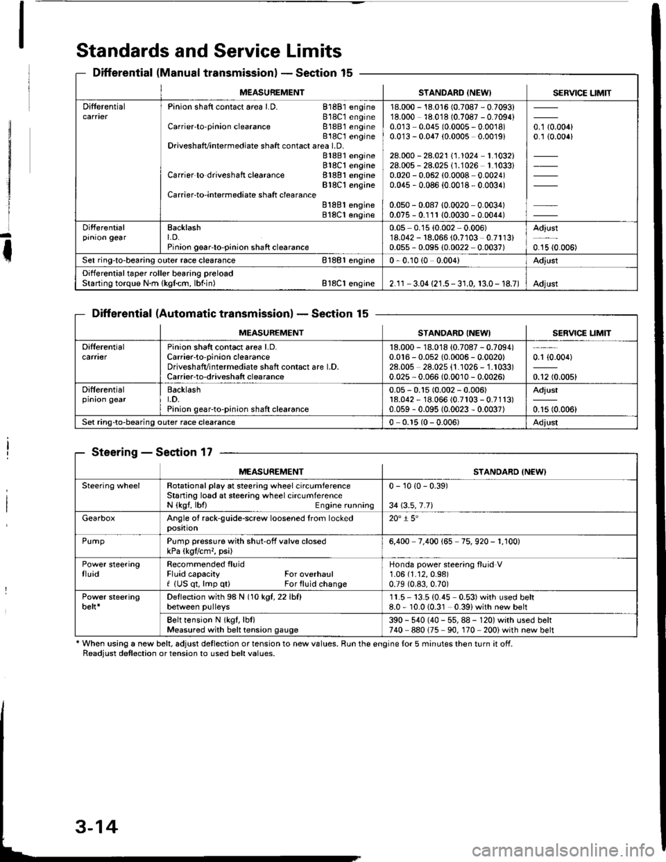
Standards and Service Limits
Differential (Manual transmissionlSection 15
Differential (Automatic transmissionlSection 15
Steering - Section 17
' When using a new belt, adjust detlection or tension to new values. Run the engine lor 5 minutes then turn it off.Readiust detlection or tension to used belt values.
M€ASUREMENTSTANDARD INEW) SERVICE LIMIT
DifferentialPinion shaft contact area LD. 81881 engine818C1 engineCarrier'to-pinion clearance 81881 engineB18C t engineDriveshafvintermediate shaft contact area LD.81881 engine818C1 engineCarrier to driveshaft clearance 81881 engineBlSC'l engineCarrier-to-intermediate shatt clearanceB188l engine818C1 engine
18.000 - 18.016 (0.7087 - 0.7093)18.000 18.018 (0.7087 - 0.7094)0.0r3 0.045 (0.0005 - 0.0018)0.0'13 - 0.047 (0.0005 0.0019)
28.000 - 28.021 \1.1024-1.1032128.005 - 28.025 (1.1026 1.'1033)0.020 - 0.062 (0.0008 0.0024)0.045 , 0.086 {0.0018 - 0.0034)
0.050 - 0.087 (0.0020 0.0034)0.075 - 0.111 (0.0030 - 0.0044)
o. t aron,0.1 {0.006}
Differentialprnron gearEacklasht. D.Pinion geaFto-pinion shaft clearance
0.05 0.15 (0.002 0.006)'18.042 - 18.066 (0.7103 0.7113)0.055 - 0.095 (0.0022 0.0037)
Adjust
0.15 {0.006)
Sel ring-to-bearing outer race clearance 81881 engin€0 - 0.10 (0 0.004)Adjust
Differential taper roller bearing preloadStarting torque N.m {kgfcm, lbf.in) Bl8Cl engine2.1r - 3.04 {21.5 - 3 r.0, 13.0- 18.7)Adjust
MEASUREMENTSTANDARO INEWISERVICE LIM]T
Difterentialcarfl€rPinion shatt contact area l.D.Carrier-to-oinion clearanceDriveshafvintermediate shaft contact are l.D.Carrier-to-driveshatt clearance
18.000 - 18.018 {0.7087 - 0.7094)0.016 - 0.052 {0.0006 - 0.0020)28.00s 28.025 {1.1026 - 1.1033)0.025 - 0.066 (0.0010 - 0.0026)
0.1 {0.004)
0.12 (0.005)
Differentialprnron gearBacklasht.D.Pinion gear-to-pinion shaft clearance
0.05 - 0.15 (0.002 - 0.006)18.042 - 18.066 (0.7r03 - 0.7113)0.059 - 0.095 (0.0023 - 0.0037)
Adjust
0.15 (0.006)
Set ring-to-bearing outer race clearance0 - 0.r5 (0 - 0.006)Adjust
MEASUREMENTSTANDARD INEWI
Steering wheelRotational play at steering wheel circumferenceStaning losd at steering wheel circumferenceN {kgf, lbfl Engine running
0 - 10 {0 - 0.39)
34 \3.5,7.71
GearboxAngle of rack-guide-screw loosened from lockedposition20" i 5'
PurnpPump pressure with shut-off valve closedkPa (kgtlcm,, psi)6,400 7.400 165 75. 920 - 1. r00)
Power steeringtluidRecommended fluidFluid capacity For overhaulf (US qt, lmp q0 For fluid change
Honda power steering fluid V1.06 (1.12,0.98)
0.79 (0.83,0.70)
Power steeringbelt*Deflection with 98 N (1okgt,22lhfl
between pulleys11.5- 13.5 (0.45 0.53)with used belt8.0 - 10.010.31 0.39)with new belt
Belt tension N lkgf, lbl)Measured with belt tension gauge390 - 540 (40 - 55, 88 - 120) with used belt740 880175 90. 170 200) with new belt
Page 143 of 1413
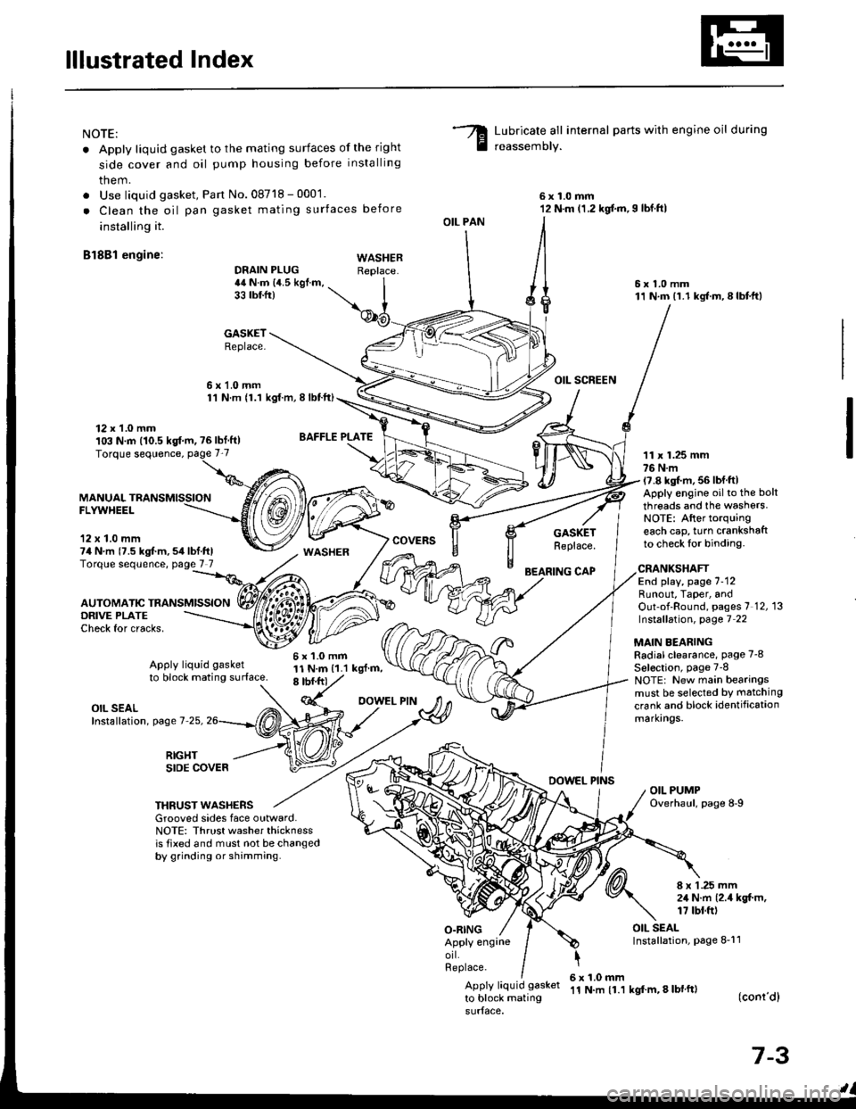
lllustrated Index
NOTE:
. Apply liquid gasket to the mating surfaces of the right
side cover and oil pump housing before installing
them.
. Use liquid gasket, Pan No.08718 - 0001.
. Clean the oil pan gasket mating surfaces before
installing it.
Bl8Bl engine: wAsHEF
Lubricate all internal parts with engine oil during
reassemory.
6x1.0mm12 N.m (1.2 kgf.m,I lbf.ftl
6x1.0mm11 N.m (1.1 kgf.m,8lbtft)
OIL SCREEN
11 x 1.25 mm76 N.m17.8 kgl.m, 56 lbf ftlApply engine oilto the bolt
threads and the washers.NOTE: After torquingeach cap, turn crankshaftto check lor binding.
DRAIN PLUG44 N.m {4.5 kgf.m,33 tbtfr)
GASKETReplace.
6x1.0mm1'l N.m {1.1 kgt.m, I lbtft)
OIL PAN
O.RING
GASKETReplace.
BEARING CAP
12 x 1.0 mm103 N.m (10.5 kgf.m, ?6lbf ft)
MANUALFLYWHEEL
'12 x 1.0 mm74 N.m {7.5 kgt m,54lbf.ftlTorque sequence, page 7 7
DRIVE PLATECheck for cracks,
AUTOMATIC TRANSMISSION
WASHER
6x1.0mm11 N.m {1.1 kgl.m,8 tbf.frt
CRANKSHAFTEnd play, page 7-12Runout, Taper, andOut-of-Round, pages 7 12, 13Instsllation, page 7 22
MAIN BEARINGRadial clearance, page 7-8
Sel€ction, page 7-8NOTE: New main bearingsmust be selected by matching
crank and block identificationmarkrngs.
Apply liquid gasket
to block mating surface.
OIL SEALInstallation, page 7-25,
RIGHTSIDE COVERDOWEL PINSOIL PUMPOverhaul, page 8-9THRUST WASHERSGrooved sides face outward.NOTE: Thrust washer thicknessis tixed and must not be changedby grinding or shamming.
8 x 1 .25 mm2,1 N.m {2.4 kgt m,17 tbt.ft)
OIL SEALInstallation, page 8-11Apply engrneorl.Replace.
Apply liquid gasket
to block mating
6x1.0mm'11 N.m {1.1 kgf'm, 8 lbl ft)(conr'dl
7-3
Page 148 of 1413
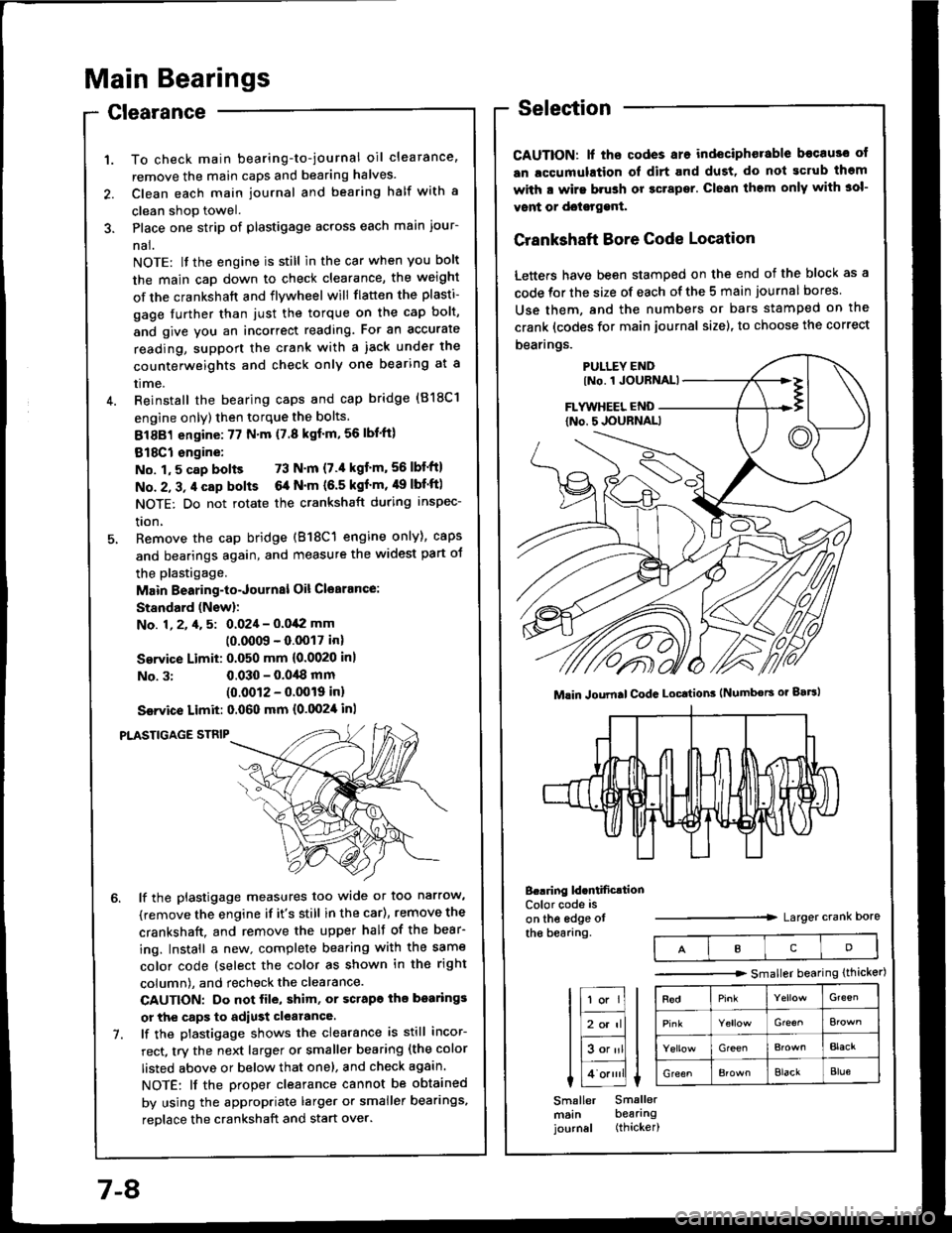
Main Bearings
Clearance
To check main bearing-to-journal oil clearance,
remove the main caps and bearing halves.
Clean each main journal and bearing half with a
clean shop towel.
Place one strip of plastigage across each main iour-
nal.
NOTE: lf the engine is still in the car when you bolt
the main caD down to check clearance, the weight
of the crankshaft and flywheel will flatten the plasti-
gage further than just the torque on the cap bolt,
and give you an incorrect reading. Fot an accurate
reading, support the crank with a iack under the
counterweights and check only one bearing at a
trme.
Reinstall the bearing caps and cap bridge (818C1
engine only) then torque the bolts.
81881 engine:77 N'm (7.8 kgf'm,56lbl'ft)
818C1 engine:
No. 1,5 cap bolts 73 N'm (7.'l kgt'm,56lbf'ftl
No. 2, 3, 4 cap bolts 6a N'm (6.5 kgf'm, 49 lbf'ftl
NOTE: Do not rotate the crankshaft during inspec-
tron,
Remove the cap bridge (818C1 engine only), caps
and bearings again, and measure the widest part oJ
the plastigage.
Main Bearing-to-Journal Oil Cl€arance:
Standard (Newl:
No. 1, 2, 4, 5: 0.024 - 0.042 mm
10.0009 - 0.0017 inl
Service Limit: 0.050 mm {0.0020 inl
No. 3:0.030 - 0.0,18 mm(0.0012 - 0.0019 inl
Ssrvice Limit: 0.060 mm {0.0024 inl
PLASTIGAGE STNIP
lf the plastigage measures too wide or too narrow,
(remove the engine if it's still in the car), remove the
crankshaft. and remove the upper half of the bear-
ing. Install a new. complete bearing with the same
color code (select the color as shown in the right
column), and recheck the clearance.
CAUTION: Do not file, shim, or scrapo ihe bo.rings
or the caps to adiust clearance.
lf the plastigage shows the clearance is still incor-
rect, try the next larger or smaller bearing (the color
listed above or below that one), and check again.
NOTE: lf the Droper clearance cannot be obtained
by using the appropriate larger or smaller bearings,
reolace the crankshaft and start over.
Selection
CAUTION: lf ths codes are indeciphorable becau3o ot
an lccumulation ol dirt and dust, do not gcrub thgm
with a wirs brush or gcrapsr. Clean them only with 3ol-
vont or doisrggnt.
Crankshaft Bore Code Location
Letters have been stamped on the end of the block as a
code for the size of each of the 5 main journal bores
Use them, and the numbers or bars stamped on the
crank (codes for main journal size), to choose the correct
bearings.
B..ring ld.ntificrtionColor code is
on the edge otthe bearang.Larger crank Dore
Mlin Joumal CodG Locttion3 (Numbors or gaBl
IcD
tr;;lIl
Itr-tl
lE;tl I tlHlt
I Lo.""li L
Smaller Smallermsin bearingjournal (thicker)
-------.r> smaller bearing (thicker)
G'een
Gre€^
GreenBlacr
GreenElackBlue
7-8
Page 165 of 1413
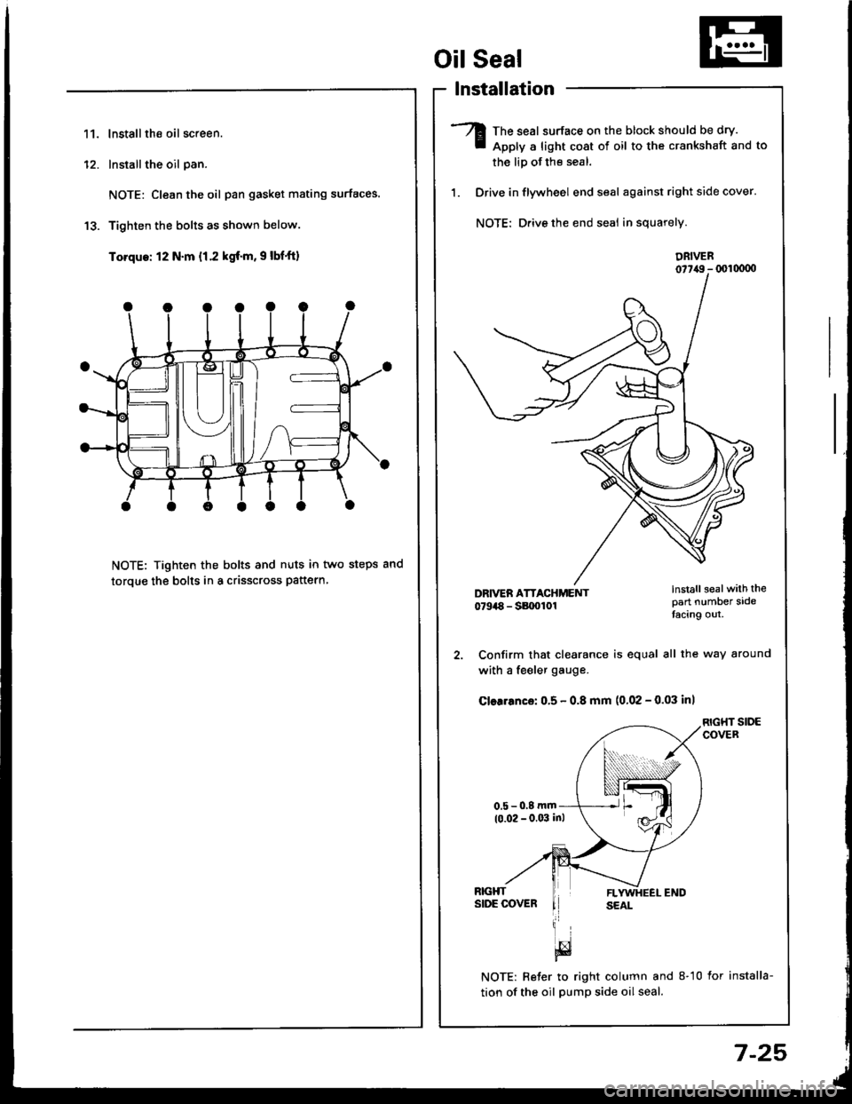
11.lnstallthe oil screen.
Installthe oil pan.
NOTE: Clean the oil pan gasket mating surfaces.
Tighten the bolts as shown below.
Torque: 12 N.m {1.2 kgf.m, 9 lbf'ft)
NOTE: Tighten the bolts and nuts in two steps and
toroue the bolts in a crisscross pattern
1'�I
Oil Seal
lnstallation
The seal surface on the block should be dry.
Apply a light cost of oil to the crankshaft and to
the liD of the seal.
Drive in flywheel end seal against right side cover.
NOTE: Drive the end seal in squarely.
DRIVER07t,49 - (xll(xtoo
2. Confirm that clearance is equal all the way around
with a fe€ler gauge.
Cler.6nce: 0.5 - 0.8 mm (0.02 - 0.03 inl
RIGHT SIDECOVER
NOTE: Reter to right column and 8-10 lor installa-
tion of the oil pump side oil seal.
lnstall sealwith thepart number sidetacing out.
7-25
Page 340 of 1413
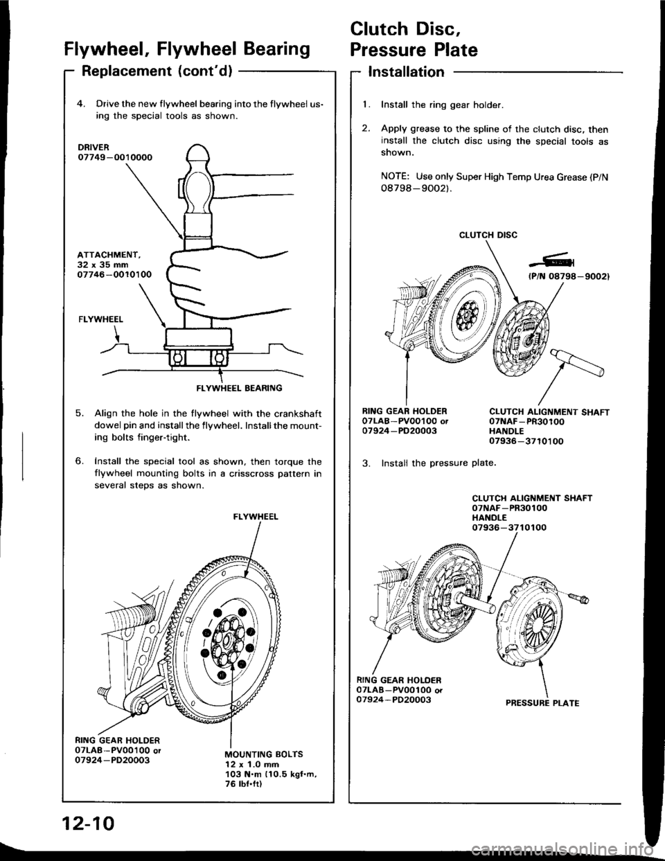
Clutch Disc,
l.
t
Flywheel, Flywheel BearingPressure Plate
Replacement (cont'd)Installation
Install the ring gear holder.
Apply grease to the spline of the clutch disc, theninstall the clutch disc using the special tools assnown.
NOTE: Use only Super High Temp Urea Grease (P/N
08798-9OO2).
CLUTCH DISC
RING GEAR HOLDEROTLAB-PVOOI O0 ot07924-PD20003
3. Instali the pressure
CLUTCH ALIGNMENT SHAFT07NAF-PR30100HANDLE07936-3710100
plate.
CLUTCH ALIGNMENT SHAFToTNAF-PR30100HANDLE
PRESSURE PLATE
12-10
4. Drive the new flywheel bearing into the flywheel us-
ing rhe special tools as shown.
DRIVER07749-O010000
ATTACHMENT.32x35mm07746-OOlO100
o.
5.
FLYWHEEL
Align the hole in the flywheel with the crankshaft
dowel pin and installthe flywheel. Installthe mount-
ing bolts finger-tight.
Install the special tool as shown, then torque the
flywheel mounting bolts in a crisscross pattern in
several steDs as shown.
MOUNTING BOLTS12 x 1.0 mm103 N.m 110.5 kgf.m,76 tbf.fr)
FLYWHEEL BEARING
FLYWHEEL
07936-3710100
t\_
Page 395 of 1413
The Automatic Transmission is a combination of a 3-e,ement torque convefter and triple-shaft electfonically controlled
automatic transmission which provides 4 speeds forward and 1 speed reverse. The entire unit is positioned in line with
the engine.
Torque Converter, Gears and Clutches
The torque converter consists of a pump, turbine and stator assembly in a single unit, The torque converter is connected
to the engine crankshaft so they turn together as a unit as the engine turns. Around the outside of the torque converter
is a ring gear which meshes with the starter pinion when the engine is being staned. The entire torque converter assem-
bly serves as a flywheel while transmitting power to the transmission mainshaft.
The transmission has three parallel shafts, the mainshaft. countershaft and sub-shaft. The mainshatt is in line with the
engine crankshaft.
The mainshaft includes the clutches for 1 st, and 2ndl4th, and gears for 3rd. 2nd, 4th, reverse and l st (3rd gear is in-
tegral with the mainshaft, while reverse gear is integral with the 4th gear).
The countershaft includes the 3rd clutch and gears Ior 3rd, 2nd,4th, reverse, lst and parking. Reverse and 4th gears
can be locked to the countershaft at its center, providing 4th gear or reverse, depending on which way the selector is moved.
The sub-shaft includes the lst-hold clutch and gears for 1st and 4th
The gears on the mainshait are in constant mesh with those on the countershaft and sub-shaft. When certain combina-
tions of gears in the transmission are engaged by the clutches, power is transmitted from the mainshaft to the counter-
shaft via the sub-shatt to provide @, E, tr. tr and @ position.
Electronic Control
The electronic control system consists of the Transmission Control Module {TCM), sensors, and 4 solenoid valves. Shift-
ing and lock-up are electronically controlled for comfortable driving under all conditions.
The TCM is located below the dashboard, behind the left side kick panel on the driver's side.
Hydraulic Control
The valve bodies include the main valve body, secondary valve body, regulator valve body. servo body, and lock-up valve
body throuqh the respective separator plates.
They are bolted on the torque converter housing.
The main valve body contains the manual valve, 1-2 shift valve, 2-3 shift valve, Clutch Pressure Cont.ol (CPC) valve,
4th exhaust valve, relief valve, and oil pump gears.
The secondary valve body contains the 4-3 kick-down valve,3-2 kick-down valve,2-3 orifice cont.ol valve, 3-4 shitt
valve, orifice control valve. modulator valve, and servo control valve
The regulator valve body contains the pressure regulator valve. lock-up control valve, torque converter check valve, and
cooler check valve.
The servo bodv contains the servo valve which is integrated with the reverse shift fork, throttle valve B, and accumulators.
The lock-ug valve bodv contains the lock-up shift valve and lock-up timing B valve. and is bolted on the secondary valve
body.
Fluid from the regulator passes through the manual valve to the various control valves.
Shitt Control Mochanism
Input to the TCM i.om various sensors located throughout the car determines which shift control solenoid valve should
be activated.
Activating a shift control solenoid valve changes modulator pressure, causing a shift valve to move. This pressurizes
a line to one of the clutches. engaging that clutch and its corresponding gear.
Lock-up Mechanism
In @ position. in 2nd, 3rd and 4th, and E position in 3rd, pressurized tluid can be drained from the back of the tor-
que converter through an oil passage, causing the lock-up piston to be held against the torque converter cover. As this
takes Dlace, the mainshaft rotates at the same speed as the engine crankshatt. Together with hydraulic control, the TCM
optimizes the timing ol the lock-up mechanism.
The lock-up valves control the range of lock-up according to lock-up control solenoid valves A and B, and throttle valve B
When lock-up control solenoid valves A and B activate, modulator pressure changes. Lock-up control solenoid valves
A and B are mounted on the torque converter housing, and are controlled by the TCM.
(cont'd)
14-3
Page 403 of 1413
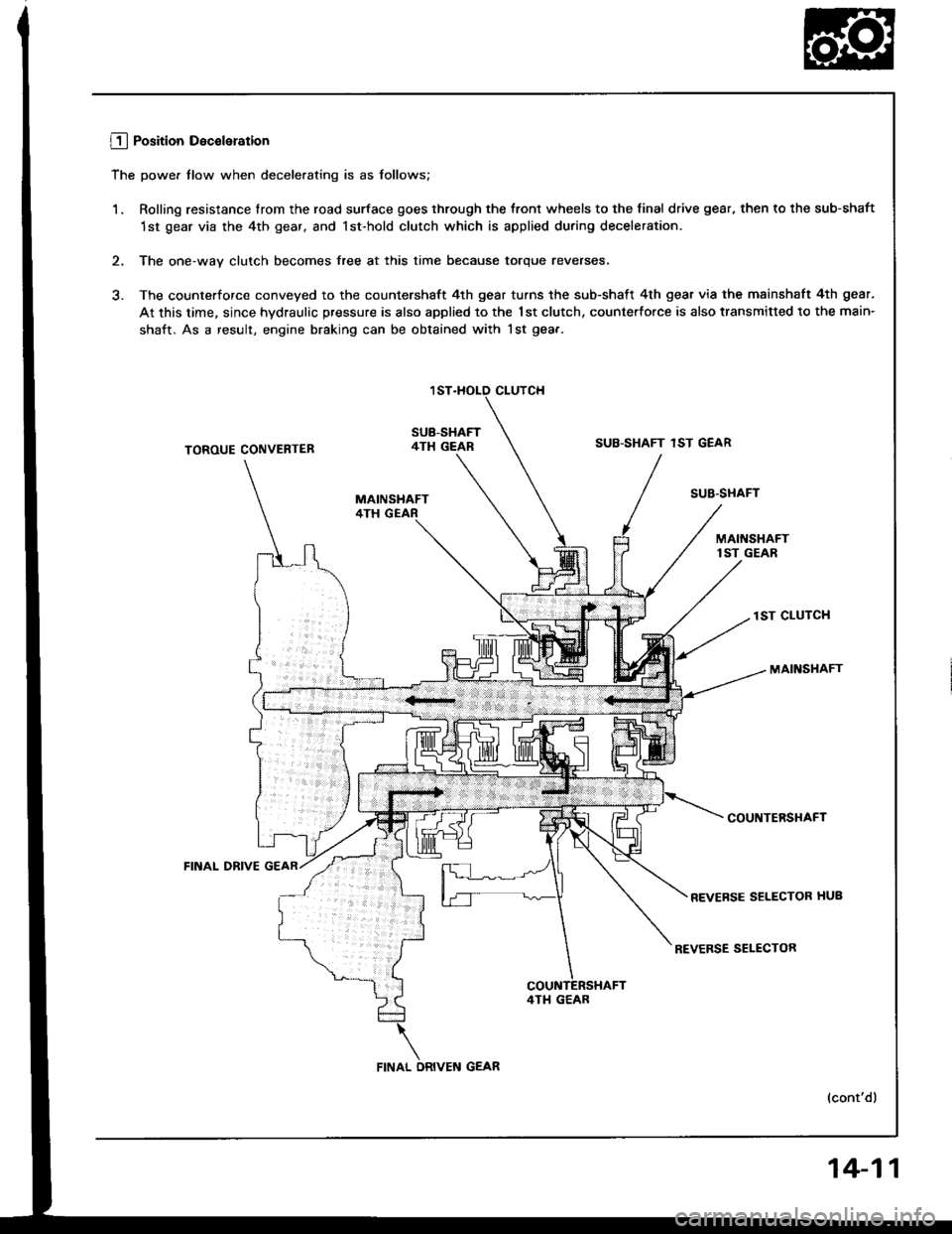
L!_j Position Deceleration
The power tlow when decelerating is as follows;
1. Rolling resistance lrom the road surface goes through the tront wheels to the final drive gear, then to the sub-shaft
1st gear via the 4th gear, and lst-hold clutch which is applied during deceleration.
2. The one-way clutch becomes free at this time because torque reverses.
3. The counterforce conveyed to the countershaft 4th gear turns the sub-shaft 4th gear via the mainshaft 4th gear.
At this time, since hydraulic pressure is also applied to the 1st clutch, counterfo.ce is also transmitted to the main-
shaft. As a result, engine braking can be obtained with lst gea.-
CLUTCH
SUB-SHAFT4TH GEARSUB-SHAFT 1ST GEARTOROUE CONVENTER
FINAL DRIVE
SUB'STIAFT
lST CLUTCH
MAINSHAFT
COUNTERSHAFT
REVEFSE SELECTOR HUB
REVERSE SELECTOR
(cont'dl
4TI1 GEAB
14-11
Page 480 of 1413
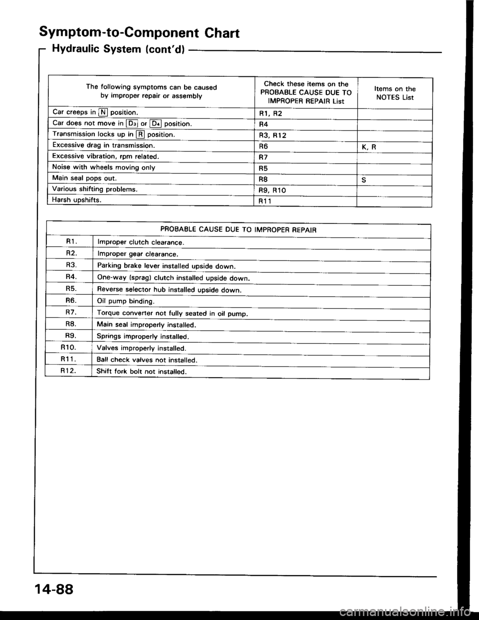
Symptom-to-Component Ghart
Hydraulic System (cont'd)
The following symptoms can be caused
by improper repair or assemblv
Check these items on the
PROBABLE CAUSE DUE TO
IMPROPER REPAIR List
Items on the
NOTES List
Car creeps in E position.R1, R2
Car does not move in @ or @ position.R4
Transmission locks up in @ position.R3, Rl2
Excessive drag in transmission.R6K.R
Excessive vibration, rom related.R7
Noise with wheels moving onlyR5
Main seal pops out.R8
Various shifting problems.R9, R1O
Harsh upshifts.R11
PROBABLE CAUSE DUE TO IMPROPER REPAIR
R1lmproper clutch cleatance.
R2.lmDroDer qear clearance.
Parking brake lever installed upside down.
One-way (spragl clutch installed upside down,
Reverse selector hub installed upside down.
Oil oumo bindind
Torque converter not fully seated in oil pump.
Main seal improperly installed.
Springs improperly installed,
Valves improperly installed.
Ball check valves not installed.
Shitt fork bolt not installed.
R3.
R4.
R5.
R6.
R7.
R8.
R9.
R10.
R11
R12.
14-88
Page 481 of 1413
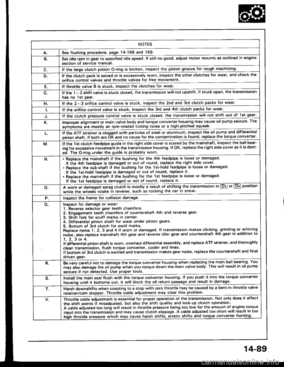
NOTES
A.See flushing procedure, page l4-168 and 169.
B.Set idle rpm in gear to specitied idle speed. lf still no good, adiust motor mounts as outlined in engine
section of service manual.
lf the large clutch piston O-ring is broken, inspect the piston groove for rough machining.
lf the clutch pack is seized or is excessively worn, inspect the other clutches Jor wear, and check the
orifice control valves and throttle valves for free movement.
E.It throttle valve B is stuck, inspect the clutches for wear.
lf the 1-2 shift valve is stuck closed, the transmission will not upshift. lI stuck open, the transmission
has no lst gear.
H.lf the 2-3 orifice control valve is stuck, inspect the 2nd and 3rd clutch packs for wear.
ll the orifice cont.ol valve is stuck, inspect the 3rd and 4th clutch packs for wear.
lf the clutch Dressure control valve is stuck closed, the transmission will not shilt out of 1st gear.
K.improper alignment or main valve body and torque converter housing may cause oil pump seizure. The
symptoms ale mostly an rpm-related ticking noise or a high-pitched squeak.
L.ll the ATF strainer is ctogged with panicles of steel or aluminum, inspect the oil pump and ditferential
pinion shaft. lt both are OK and no cause lor the contamination is found, replace the torque converter.
M.lf the 1st clutch feedpipe guide in the right side cover is scored by the mainshaft, inspect the ball bear-
ing for excessive movement in the transmission housing. lf OK. replace the right side cover as it is dent-
ed. The O-ring under the guide is probably worn.
N.ReDlace the mainshstt if the bushing for the 4th feedpipe is loose or damaged.
It the 4th feedpipe is damaged or out ot tound, replace the right side cover'
Replace the subjshaft it thtbushing for the 1st-hold Jeedpipe is loose or damaged.
lf the 1st-hold feedpipe is damaged or out of round, replace it.
Replace the mainshaft if the bushing lor the 1st feedpipe is loose or damaged.
lf the lst feedpipe is damaged or out ot round, replace it.
o.A *o- r, da."s"d "p-g clutch is mostly a result of shifting the transmission in El or Lq! position
while the wheels rotate in reverse, such as rocking the car in snow.
P.InsDect the frame for collision damage.
o.Inspect for damage or wear:
1. Reverse selector gear teeth chamfers.
2. Engagement teeth chamters of countershaft 4th and reverse gear.
3. Shift fork for scutt marks in center.
4. Differential Dinion shaJt for wear under pinion gears.
5. Bottom of 3rd clutch for switl marks.
Replace items 1 , 2, 3 and 4 it worn or damaged. lf transmission makes clicking, grinding or.whirring
noise, atso replace mainshaft 4th gear and reverse idler gear and countershaft 4th gear in addition to
1,2,3ot4.lf ditiersntial Dinion shaft is worn, overhaul differential assembly, and replace ATF strainel, and thoroughly
clean transmission, tlush torque convertet, cooler and lines.
lf bottom of 3rd clutch is swirled and transmission makes gear noise, replace the countershaft and tinal
driven gear.
R.Be wry careful not to dsmage the torque converter housing when replacing the main ballbearing. You
may al;o damage the oil pump when you torque down the main valve body. This will result in oil pump
seizure it not detected. Use proper tools.
qInstall the main seal tlush with the torque converter housing, lf you push it into the torque converter
housing until it bottoms out. it will block the oil return passage and result in damage.
T,Harsh do\/vnshiJt"\./l,'hen coasting to a stop with zero th.ottle may be caused by a bent-in throttle valve
retainer/cam stopper. Throttle cable adjustment may clear this problem.
ifuitle cable adjustment is essential for proper operation of the transmission. Not only does it affect
the shift points if misad,usted, but also the shift quality and lock-up clutch operation'
A cable adjusted too long will result in throttle pressure being too low for the amount of engine torque
input into ihe trsnsmission and may cause clutch slippage. A cable adjusted too short will result in too
hi;h throttle pressure which may cause harsh shitts, erratic shrfts and torque con
14-89
Page 484 of 1413
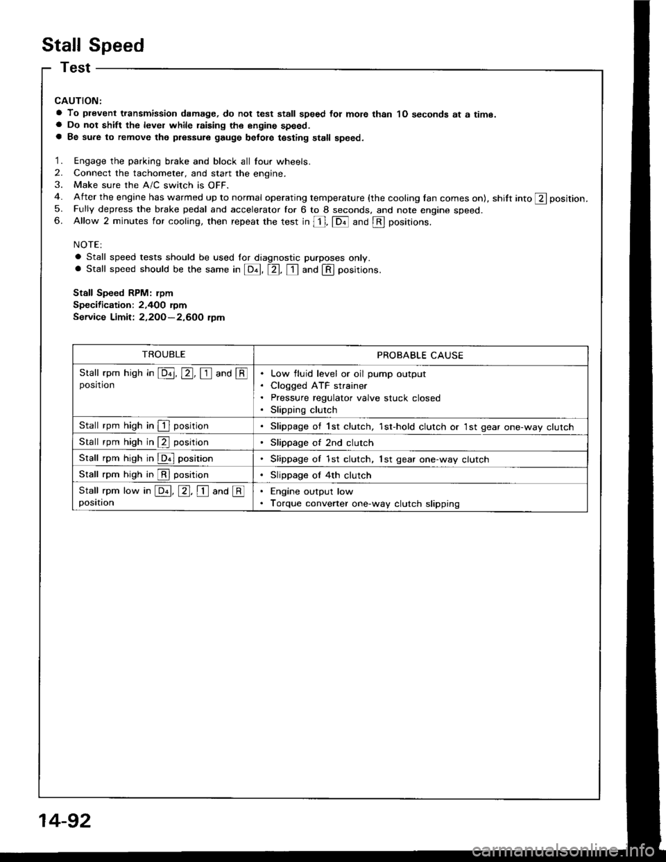
Stall Speed
CAUTION:
a To plevent transmission damage, do not test stall speed fot mote than 1O seconds at a time.a Do not shift the level while raising th€ engine speed.a Be sure to remove the pressure gauge belot€ testing stall speed.
1. Engage the parking brake and block all four wheels.
2. Connect the tachometer, and start the engine.
3. Make sure the A/C switch is OFF.
4. After the engine has warmed up to normal operating temperature (the cooling lan comes on), shift into ft position.
5. Fully depress the brake pedal and accelerator for 6 to 8 seconds. and note engine speed.6. Allow 2 minutes for cooling, then repeat the test in [, fDil and @ positions.
NOTE:
a Stall speed tests should be used lor diagnostic purposes only.. Stall speed should be the same in E, tr. tr and @ positions.
Stall Speed RPM: rpm
Specification: 2,400 rymService Limit: 2,2OO-2,600 tpm
TROUBLEPROBABLE CAUSE
Stall rpm hish in E, E, I and @posrtronLow fluid level or oil pump output
Cloqged ATF strainer
Pressure regulator valve stuck closed
Slipping clutch
Stall rpm high in I positionSlippage of 1st clutch, 1st-hold clutch or 1st gear one-way clutch
Stall rpm high in @ positionSlippage of 2nd clutch
Stall rpm high in @ positionSlippage of 1st clutch, lst gear one-way clutch
Stall rpm high in @ positionSlippage of 4th clutch
Stall rpm low in E, E, I ana @positionEngine output low
Torque converter one-way clutch slipping
14-92