wheel torque HONDA INTEGRA 1994 4.G User Guide
[x] Cancel search | Manufacturer: HONDA, Model Year: 1994, Model line: INTEGRA, Model: HONDA INTEGRA 1994 4.GPages: 1413, PDF Size: 37.94 MB
Page 486 of 1413

Pressure Testing
a While testing, be caretul of the rotating flont wheels.a Make aura litts, jacks, and sat€ty stands alo placedplop6rly {see section 1}.
CAUTION: Betore t€sting, be sure the transmission fluidis tilled to rh6 ploper l€vet.
1. Raise the car (see section i),
2. Warm up the engine {the cooling fan comes onl, thenstop the engine and connect a tachometer.
3. Connect the oil pressure gauge to each inspectionholels).
TOROUE: 18 N.m (1.8 kgf.m, 13 tbf.fr)
CAUTION: Connect ths oil prsssure gauge s€cur€_ly; be sule not to allow dust and other foleign pani_cl6s to 6nt€1 th€ inspection holo.
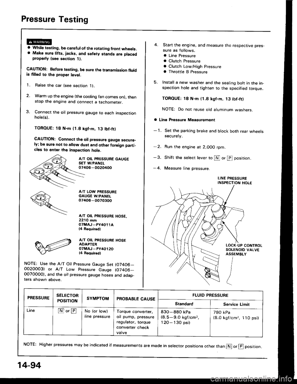
A/T OIL PRESSURE GAUGESET WPANEL07406-002oi+oo
A/T LOW PRESSUREGAUGE W/PANEL07/rO6-0O70300
A/T OIL PRESSURE HOSE,22'10 mmOTMAJ_PY4OI TA{4 Roquirod)
A/T OIL PRESSUBE HOSEADAPTEROTMAJ - PY/+O12014 Roqui.odl
NOTE: Use the A/T Oil Pressure Gauge Set (07406_O02OOO3) or A/T Low Pressure Gauge (07406-OOTO0OO). and the oil pressure gauge hoses and adap_ters shown above.
14-94
4. Start the engine, and measure the respective pres-
sure as follows.
a Line Pressure
a Clutch Pfessure
a Clutch Low/High Pressure
a Throttle B Pressure
5. Install a new washer and the sealing bolt in the in-spection hole and tighten to the specified torque.
TOROUE: 18 N'm {1.8 kgf.m, 13 tbf.ft)
NOTE: Do not reuse old aluminum washers.
a Line Pressure M€asurement
- 1 . Set the parking brake and block both rear wheelssecurely.
-2. Run the engine at 2,OOO rpm
-3. Shift the selecr lever to S or @ position.
-4. Measure line pressure.
LINE PRESSUREINSPECTION HOLE
NoTE: Higher pressures may be indicated it measurements are made in selector positions other than @ or @ position.
PRESSURESELECTOR
POStTTONSYMPTOMPROBABLE CAUSEFLUID PRESSURE
StandardService Limit
LineNo'ENo (or low)
lrne pressureTorque converter,
orl pump, pressure
regulator, to.que
convener check
valve
83O-88O kPa(8.5-9.O kgf/cm,,
120- I 30 psi)
78O kPa
{8.0 kgl/cm,, 1lO psi}
Page 618 of 1413

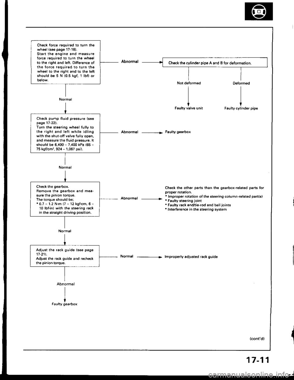
Ch6ck force r6quired to turn thowheel(see page 17-18).St6 the engine and m6asureforce required to turn the whgelto the right and left. Dilference olthe lo.ce required to turn thewho€l to the right and to the lettshould be 5 N (0.5 kgf, 1 lbf) orbelow.
Normal
Ch6ck pump fluid pressure (seepage 17-221.Turn the steering wheel lully tothe right and left whil€ idlingwith the shut-off valvo fully op6n,and measure tho fluid pressu.e. ltshould be 6,400 - 7,400 kPa (65 -
75 kg?cm,, 924 - 1,067 psil.
Normal
Abnormal -----|. Faulty gearbox
Abnormal |r
Chsck the other parts than the gearbox-ralated psrts forpropor rotstion,* lmpropor rotation ofthe steering column-rolat€d pan(sl'Faulty st6€ring jointa Faulty rack end^ie-rod end balljoints'Intederence in the steering system
lmproperly adjusted rack guide
(cont'dl
Chock the gearbox.Remove the goarbox and mea-sure the pinion torque.The torque should be;* 0.7 - 1.2 N.m (7 - 12 kgf.cm, 6 -'10 lbt in) with the steering rackin the straight driving position.
Normal
Adjust the rack guide (see page11-211.Adiust the rack guide and recheckthe pinion torque.
17-11
Page 672 of 1413

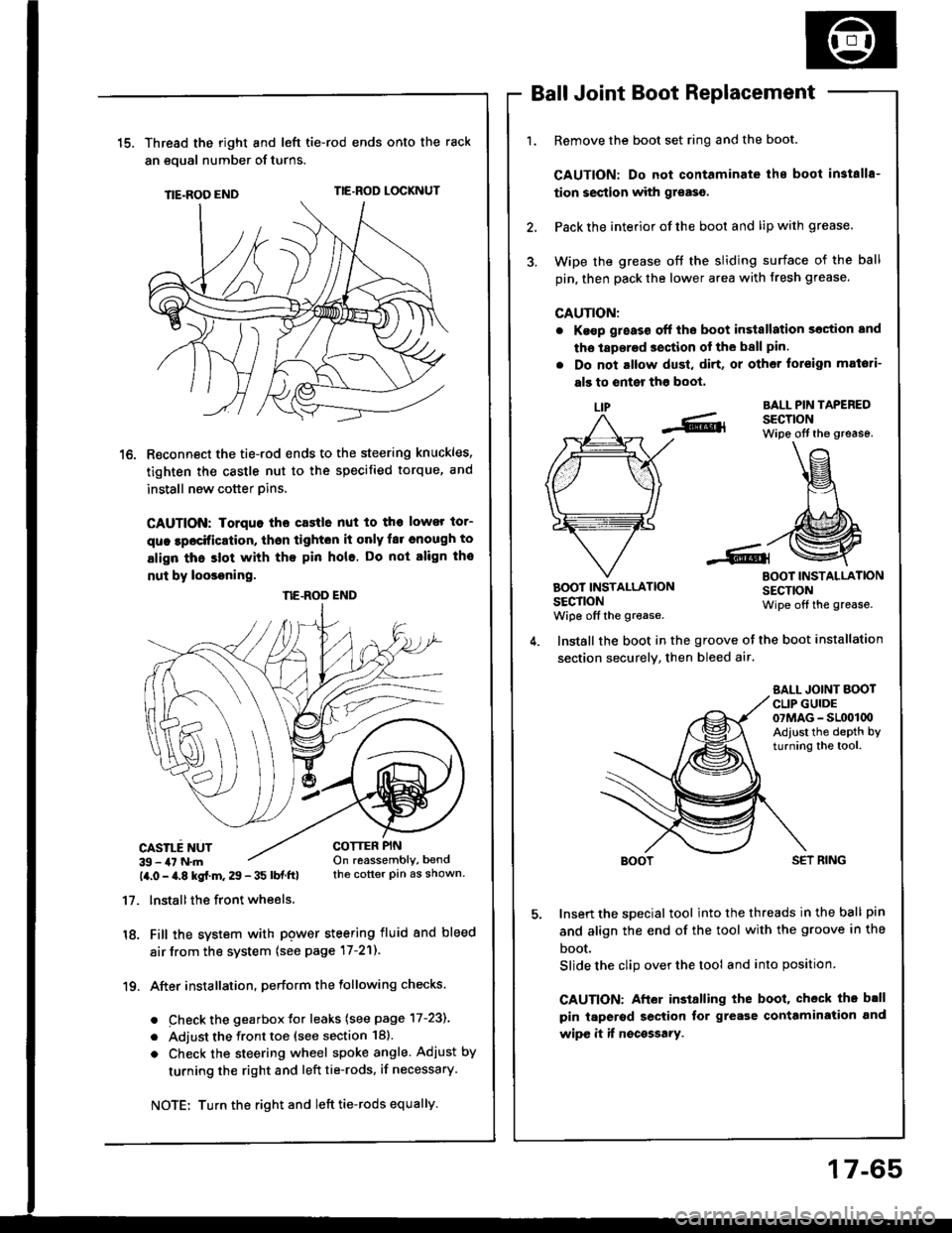
15.Thread the right and lefi tie-rod ends onto the rack
an eoual number of turns.
TIE-ROO ENDTIE.ROD LOCKNUT
R€connect the tie-rod ends to the steering knuckles,
tighten the castle nut to the specified torque, and
install new cotter pins.
CAUTION: Iorquo tho castle nut to tho lower tor-
que lpocification, thsn tighton it only far cnough to
align thc slot with tho pin hole. Do not align tho
nut by loosoning.
CASILE NUT39 - 47 N.m14.0 - a.8 kgf.m. 29 - 35 lbf ftl
17. lnstallthe front wheels.
18. Fill the system with pgwer steering fluid and bleed
air from the system (see page 17-21).
19. After installation. perform the following checks.
. Check the gearbox Jor leaks (see page 17-231
. Adjust the front toe (see section 18).
o Check the steering wheel spoke angle. Adjust by
turning the right and left tie-rods, if necessary.
Ball Joint Boot Replacement
Remove the boot set ring and the boot.
CAUTION: Do not contaminate ihe boot in3talls-
tion section with gr€aso.
Pack the interior of the boot and lip with grease.
Wipe the grease off the sliding surface of the ball
pin, then pack the lower area with fresh grease.
CAUTION:
. Ke€p g;eass off the boot in3tallation section and
tho laperad section of the ball pin.
. Do not altow dust, di.t, or other toreign mat6ti-
als to enter tho boot,
LIPBALL PIN TAPEREDSECTIONWipe off the grease.
BOOT INSTALLATIONSECTIONwiDe off the grease.
BOOT INSTALLATIONSECTIONWipe off the grease.
COTTER PINOn reassembly, bendthe cotter pin as shown.
Install the boot in the groove ot the boot installation
section securely, then bleed air.
SALL JOINT BOOTCLIP GUIDE07MAG - SL(x)l00Adiust the depth byturning the tool.
SET RING
Insert the special tool into the threads in the ball pin
and align the end of the tool with the groove in the
boot.
Slide the clip over the tool and into position
CAUTION: After installing the boot, check th. b.ll
pin taperod section tor grease contamiration and
wipe it if nocossary.
NE.ROD END
Turn the right and left tie-rods equally.
17-65
Page 1190 of 1413

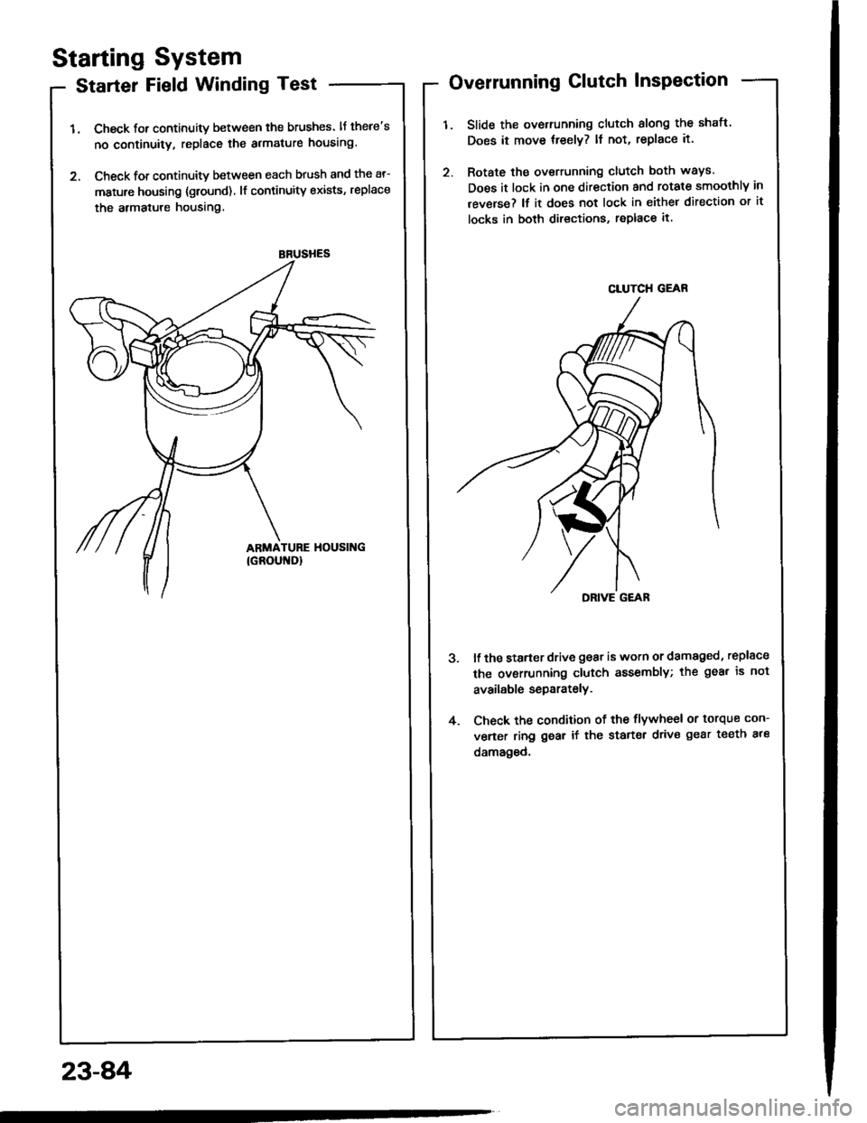
BRUSHES
Starting System
Starter Field Winding Test
1. Check for continuity between the brushes. lf there's
no continuity, replace the armature housing.
2. Check for continuity between each brush and the ar-
mature housing {ground) lf continuity exists, replace
the armatule housing.
Overrunning Clutch InsPection
Slide the overrunning clutch slong the shatt.
Does it move treely? ll not, replace it.
Rotate the overrunning clutch both ways.
Does it lock in one direction and rotate smoothly in
reverse? lf it does not lock in either direction or it
locks in both directions, replace it.
DRIVE G€AR
ll the starter drive gear is worn or damaged, replsce
the ovsrrunning clutch assembly; the gea. is not
available separately.
Check the condition of the flywheel or torque con-
verter ring gear if the starter drive gear teeth ale
damaged.
4.
23-8,4
CLUTCH GEAR