HONDA INTEGRA 1998 4.G Owners Manual
INTEGRA 1998 4.G
HONDA
HONDA
https://www.carmanualsonline.info/img/13/6069/w960_6069-0.png
HONDA INTEGRA 1998 4.G Owners Manual
Page 1138 of 1681
I
,.
u
J
/
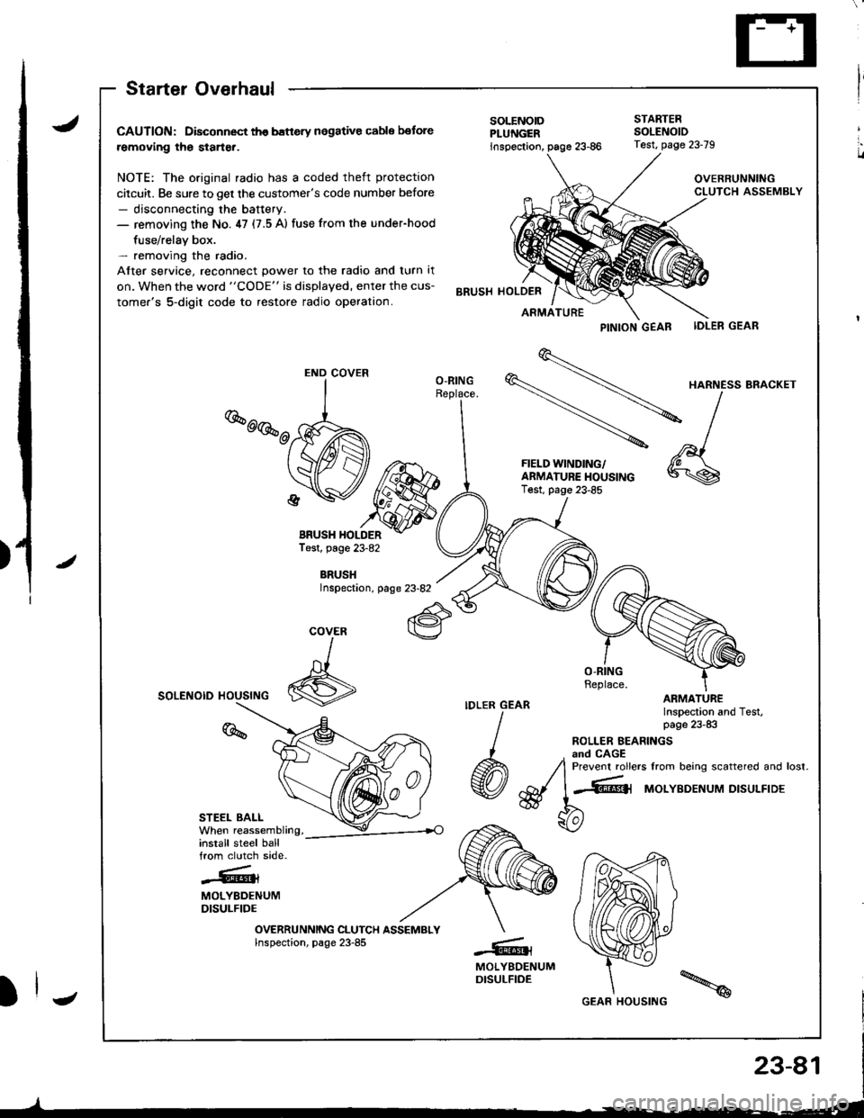
Starter Overhaul
CAUTION: Disconnect th€ banery negative cable botore
removing the starter.
NOTE: The original radio has a coded theft protection
citcuit. Be sure to get the customer's code number before- disconnecting the baftery.- removing the No. ,17 (7.5 A) fuse from the under-hood
fuse/relav box.- removing the radio.
After service, reconnect power to the radio and turn it
on. When the word "CODE" is displayed, enter the cus-
tomer's 5-digit code to restore radio operation.
BRUSH HOLDERTest, page 23-82
BRUSHInspectaon, page 23-82
SOLENOID HOUSING
STEEL BALL
install steel ballfrom clutch side.
-.''.!k.��rt{l{
MOLYBDENUMDISULFIDE
OVERRUNNING CLUTCH ASSEMBLYInspection, page 23-85
PINTON GEAB IDLER GEAR
\
HARNE'SBRA.KET
-\l
-
^,1FIELD WINDING/ 'A \
f:$i:y5J*"""
*\s
SOLENOIDPLUNGER
STARTEBSOLENOID
inspection,
BRUSH HOLDER
Test, page 23-79
OVERRUNNINGCLUTCH ASSEMBLY
ARMATURE
O-RING
COVER
I
6
%
-@t
MOLYBDENUMDISULFIDE
END COVER
GEAR HOUSING
Page 1156 of 1681
)
)
Charging System
Component Locationlndex
CHARGING SYSTEM LIGHT(ln the gauge assembly)Test, pages 23-102,103Bulb Locations, page 23-122
UNDER-HOOD FUSE/RELAY BOX(USA: HAS bUiIt-iN ELECTRICALLOAD DETECTOR (ELD) UNIT}Troubleshooting of ELD, secrion 11
BATTERYTest,
ALTERNATOR BELTInsp€ction and Adiustment, page 23_115ALTERNATORTroubleshooting, page 23'102Alternator/FegulatorTosl, pages 23-105,'106Replacement, page 107Overhaul, page 23-108
23-99
.t-
Page 1157 of 1681
a
Charging System
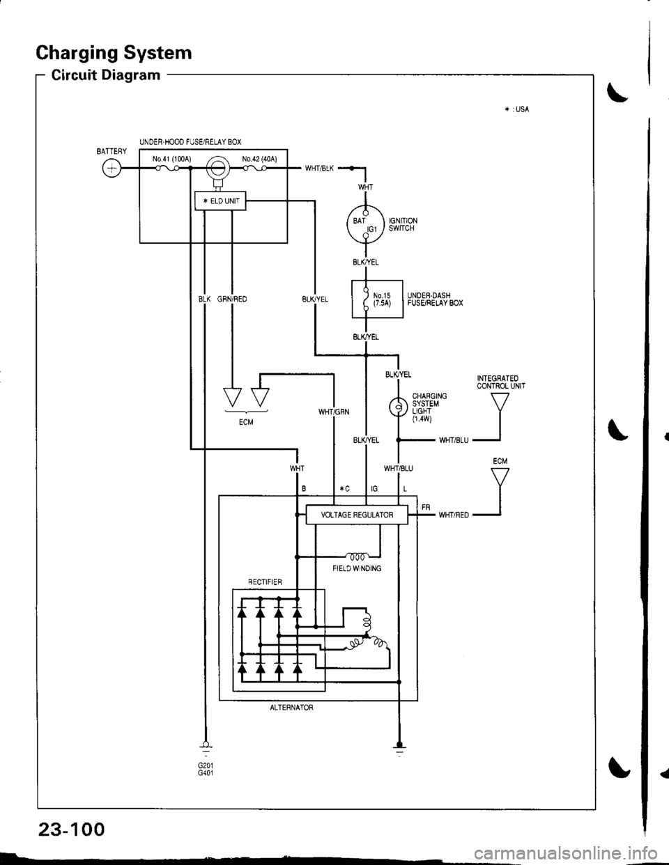
Circuit Diagram
INTEGRATEOCONTROL UNIT
V
II
ECM
V
II
UNDER.HOOD FUSE/RELAY BOX
No41 (1tl0A) /^ N0.42 (40A)
FIETDWINOING
WHT/8LU
L
GFN/REO
I
I
I
I-t
-"
ALTERNATOR
BLK/YEL
23-100
I-
Page 1158 of 1681
*l
I/'1\
/ ari orrr or cr / swlrcH
vIBtKAEtI
rt-r| ) m.rs IUNDER-DASHI t (7.5A) |FUSE/RELAYBOX
IBLK,YEL
-i * TNTEGBATEo
I CoNTROL UN|T
rh 3i{i3#' v
Ynu i
| ,."
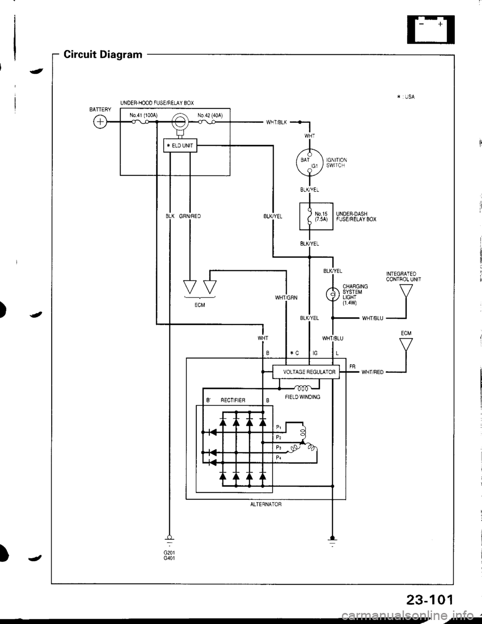
UNDEH.HOOD FUSE/RELAY BOX
No.4l (100A) ,.4 No 42 (40A)
B FTELDWTNoTNG
ECM
WHT/8LU
L
ALTERNATOF
Circuit Diagram
)
-
-
)
23-101
,f
Page 1159 of 1681
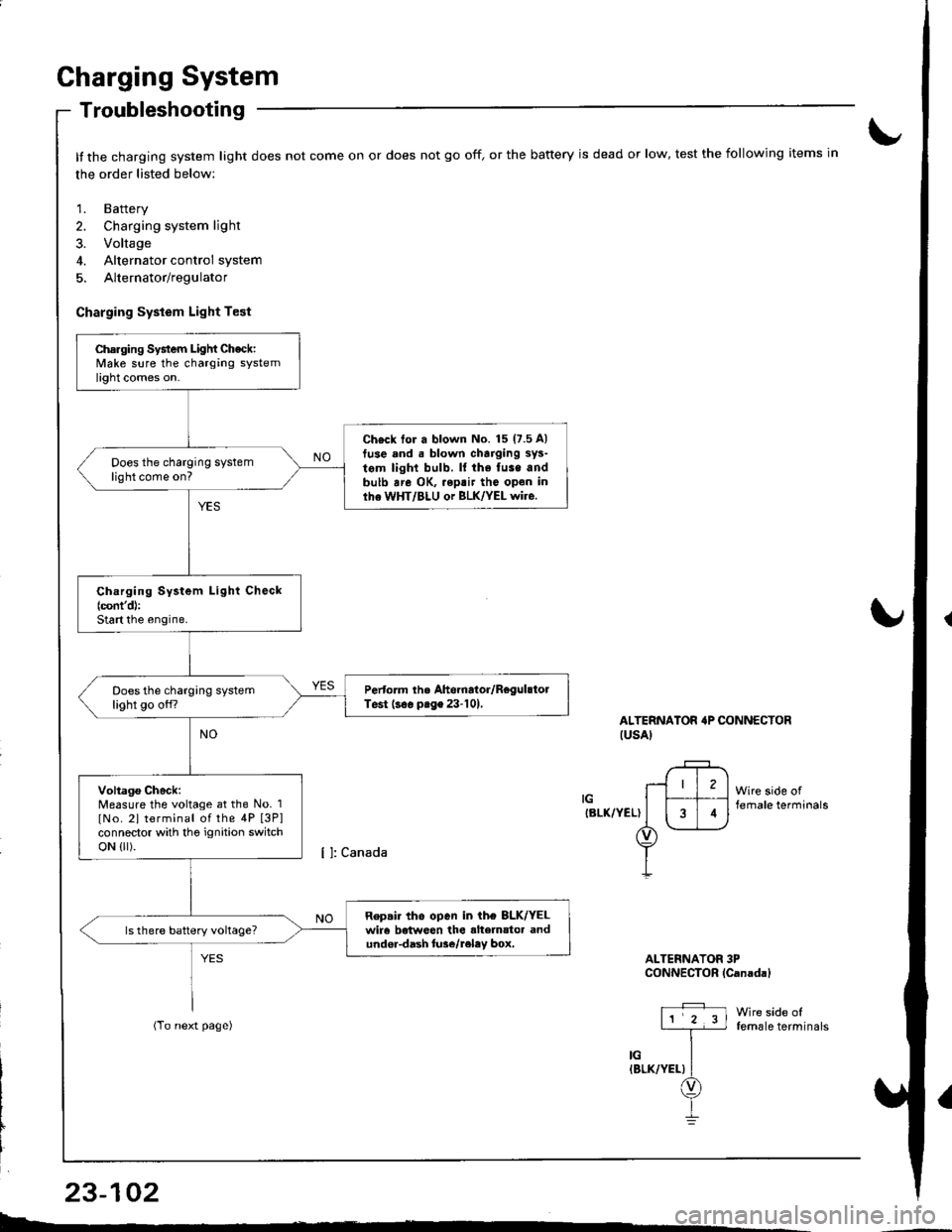
Charging System
Troubleshooting
It the charging system light does not come on or does not go off, or the battery is dead or low, test the following items in
the order listed below:
1. Battery
2. Charging system light
3. Voltage
4. Alternator control system
5. Alternator/regulator
Charging System Light Test
ALTERNATOR'P CONNECTORIUSAI
IGIBLK/YEL)
Wire side offemale terminals
Wire side offemale terminals
ALTERNATOR 3PCONNECTOR lCanadal
Charging System Light Check:Make sure the charging systemlight comes on.
Ch€ck tor a blown No. 15 (7.5 A)
tuse and . blown charging sys-
tem light bulb. ll the fuse andbulb are OK, .eptir tho open inlhe WHT/BLU or BLK/YEL wire.
Does the charging systemlight come on?
Ch.rging System Light Check(cont'd):
Start the engine.
Pertorm the Ahernator/RegulstolTest (s€. prge 23-101,Does the charging systemlight go off?
Voltago Check:Measure the voltage at the No. 1
lNo. 2l terminal of the 4P [3P]connector with tho ignition switchoN {lr).
Repair tho open in ih€ 8LK/YELwir6 betweon the alte]nator andundor-dash lure/reley box.
I4
L-*
23-102
Page 1164 of 1681
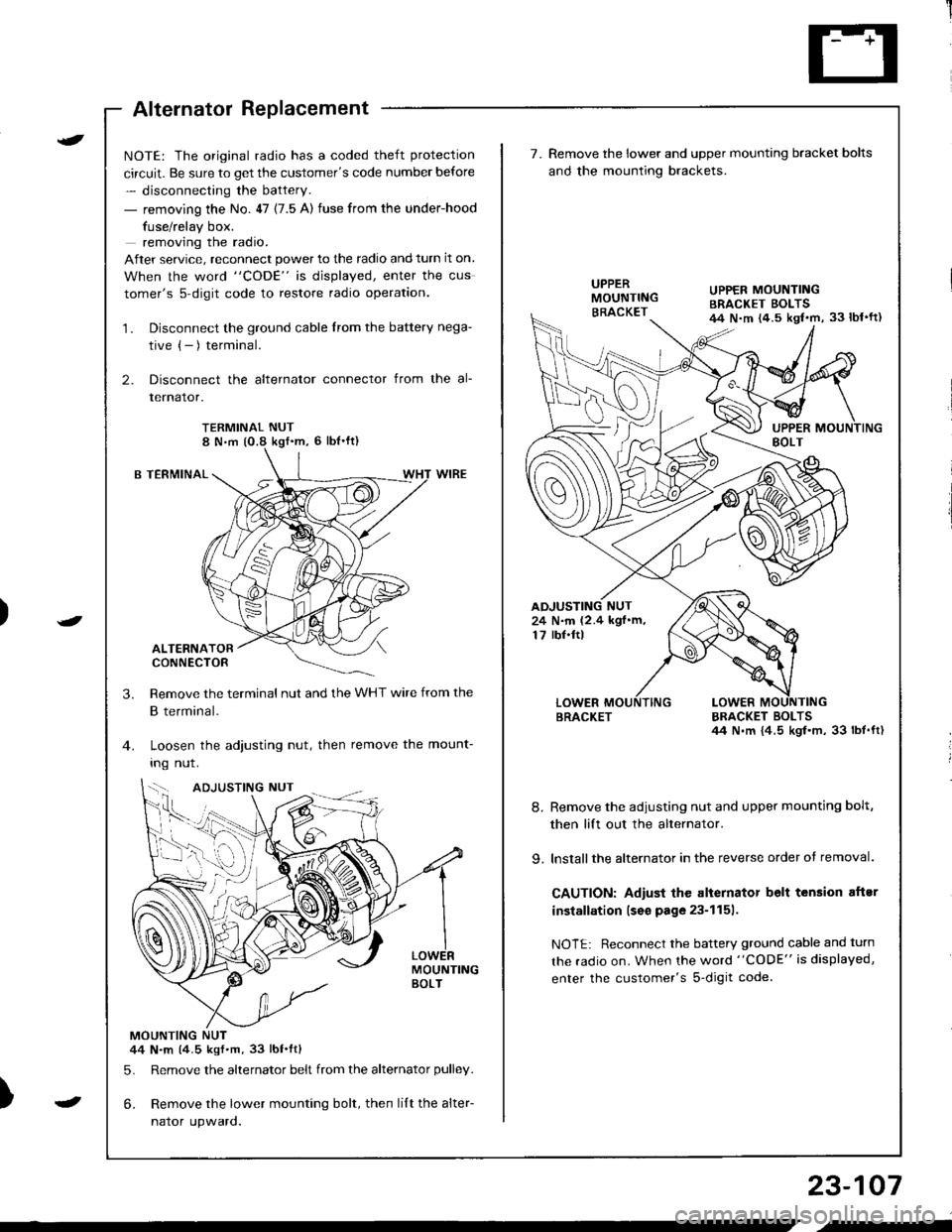
Alternator Replacement
)
t
-
NOTE: The original radio has a coded theft protection
circuit. Be sure to get the customer's code number before
- disconnecting the battery.
- removing the No. 47 (7.5 A) fuse from the under-hood
fuse/relay box.
removing the radio.
After service, reconnect power to the radio and turn it on.
When the word "CODE" is displayed, enter the cus
tomer's s-digit code to restore radio operation.
1. Disconnect the ground cable from the battery nega-
tive (- ) terminal.
2. Disconnect the alternator connector from the al-
lernalor,
TERMINAL NUT8 N,m (O.8 kgf'm, 6 lbl'ft)
B TERMINAL
ALTERNATORCONNECTOR
Remove the terminal nut and the WHT wire from the
B terminal.
Loosen the adjusting nut, then remove the mount-
Ing nut.
MOUNTINGBOLT
MOUNTING NUT44 N.m (4.5 kgf.m.33 lbt.ftl
5. Remove the alternator belt from the alternator pulley.
6. Remove the lower mounting bolt, then lilt the alter-
naror upwaro.
3.
{--,
7.Remove the lower and upper mounting bracket bolts
and the mounting brackets.
BRACKET BOLTSil4 N.m {4.5 kgl.m, 33 lbt.ft)
8. Remove the adiusting nut and upper mounting bolt,
then lift out the alternator.
9. lnstallthe alternator in the reverse order of removal.
CAUTION: Adiust the alternator belt tension aftsr
installation lseo page 23-1151.
NOTE: Reconnect the battery ground cable and turn
the radio on. When the word "CODE" is displayed,
enter the customer's s-digit code.
BRACKET
UPPER MOUNTINGBRACKET EOLTS44 N.m {4.5 kgl.m, 33 lbl'ft)
24 N.m (2.4 kgf.m,17 rbf.ftl
b-h..K
) I
23-107
-
,-
Page 1173 of 1681
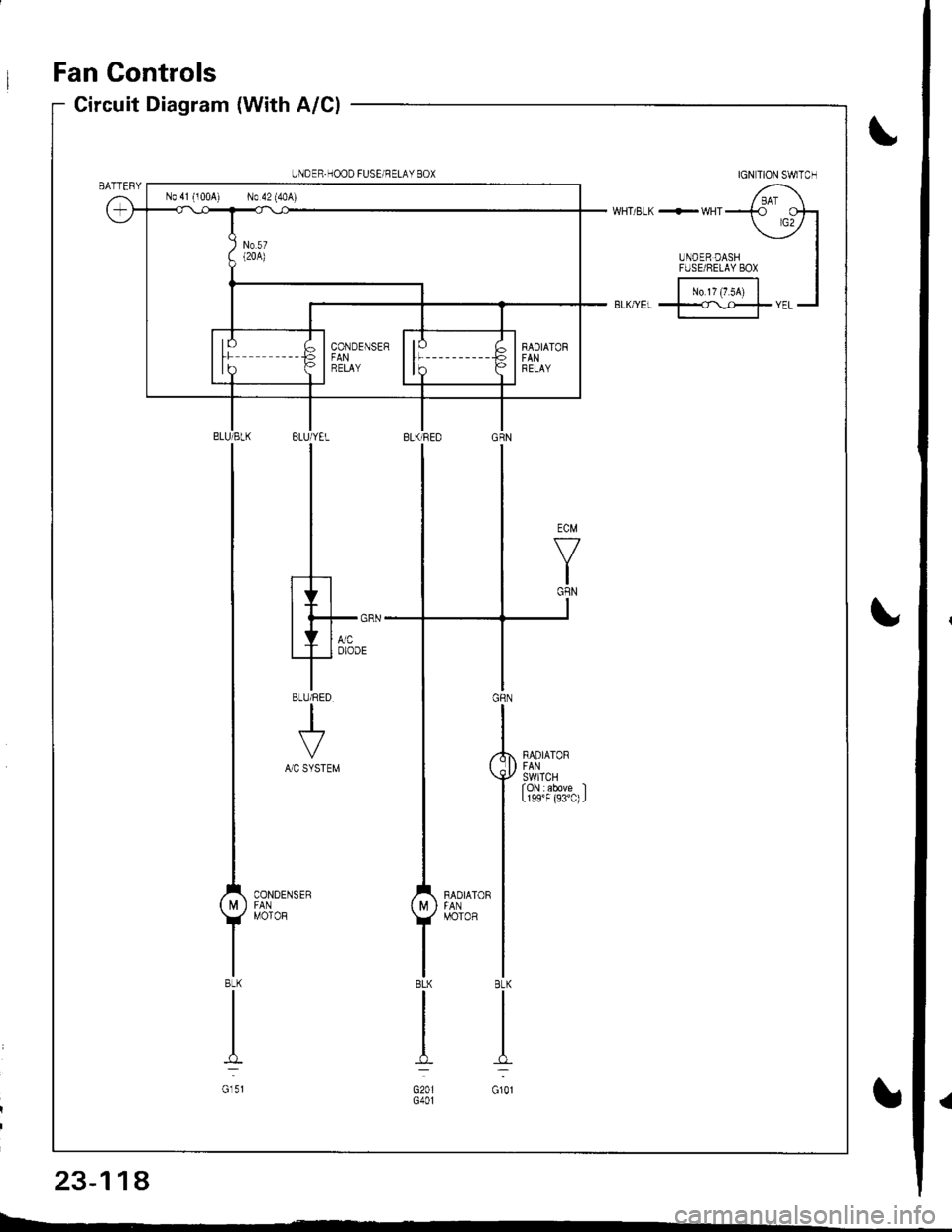
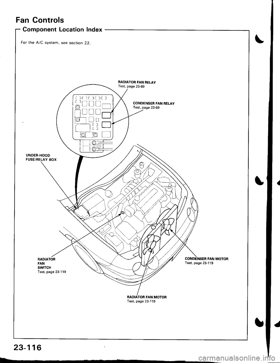
Fan Controls
RADIATORFANswtTcHTest, page 23-119
Component Location Index
For the A/C system, see section 22.
UNDER-HOODFUSE/RELAY BOX
CONDENSER FAN RELAYTest, page 23-69
RADIATOR FAN RELAYTest, page 23,69
FAN MOTORTest, page 23-119
TOR FAN MOTORTest, page 23,119
: lt tt tt tt l
c=, Ll L-t t lf l]-]l
f1 a l f -r a'r -
I i I r""""rlla-t fr -
a tL) | |Irt -
1/^ l/-\ltr.z{ N/ L
Page 1174 of 1681
Circuit Diagram (Without A/Cl
UNOEF.OASHFUSE,NELAY BOX
|-;ffi;I-YELf\-.rl]-t
BTK'EL -l
RAOIATORFANS\,YITCHfoN : above )(199'F (93'C)J
BLIVREO
BLK
I
G201G401
IGNITION SWITCH
N0.41 (lmAl No.42 (104)
RADIATORFANRELAY
23-117
.l
Page 1175 of 1681
Fan Controls
IGN TION SWITCH
/ BAI \WHT/ELK +-WHTT rcotr
UNDER DASH
-
IFUSE/8ELAY 8ox I
|-;;;l IBL(rYEL t==rYEL-l
BLUiYEL
I
I
I
.h
Ith*-'T'o'oo'
8LU/RED
+A/C SYSTEM
.,'l'**u.'
UNDER.HOOD FUSEi NELAY BOX
No 41 (100A) No 42 (40A)
23-114
Page 1180 of 1681
UNDER.DASHFUSE/RELAY 8OX
No.l5 (7.54)
No 2s (7 5A)
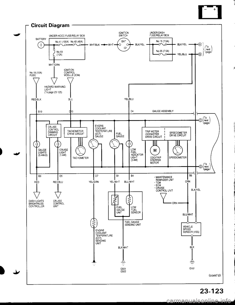
Gircuit Diagram
WHTiGRN
| $il,�4,
V
MODULE(ICM)
ru{no unrno I(To pase 23 12s)
|BtU
No.rs (10A)FUSE
V
I
GAUGE ASSEMBLY
YEUBLU
t,,
| ,,J,,
1l
|;;il'-II SPEED II SENSoBIVSS) |-t-
. MAINTENANCEREMINDER UNIT' TCM' ECM' CRUISECONTROT UNlT
f7
I-oRN
BLKMHT
I
G501
I'YEUGRN YE
ln
tl
P**,,,'
ffirxl-"
louRED/BLU
.J'-
CRUISECONTROLUNIT
BLK
I
G10l
23-123
-/
UNDEF HOOD FUSE/RELAY BOX



![HONDA INTEGRA 1998 4.G Owners Manual Circuit Diagram (Without A/Cl
UNOEF.OASHFUSE,NELAY BOX
|-;ffi;I-YELf\-.rl]-t
BTKEL -l
RAOIATORFANS\,YITCHfoN : above )(199F (93C)J
BLIVREO
BLK
I
G201G401
IGNITION SWITCH
N0.41 (lmAl No.42 (104)
RAD HONDA INTEGRA 1998 4.G Owners Manual Circuit Diagram (Without A/Cl
UNOEF.OASHFUSE,NELAY BOX
|-;ffi;I-YELf\-.rl]-t
BTKEL -l
RAOIATORFANS\,YITCHfoN : above )(199F (93C)J
BLIVREO
BLK
I
G201G401
IGNITION SWITCH
N0.41 (lmAl No.42 (104)
RAD](/img/13/6069/w960_6069-1173.png)
