fuse HONDA INTEGRA 1998 4.G Workshop Manual
[x] Cancel search | Manufacturer: HONDA, Model Year: 1998, Model line: INTEGRA, Model: HONDA INTEGRA 1998 4.GPages: 1681, PDF Size: 54.22 MB
Page 1255 of 1681
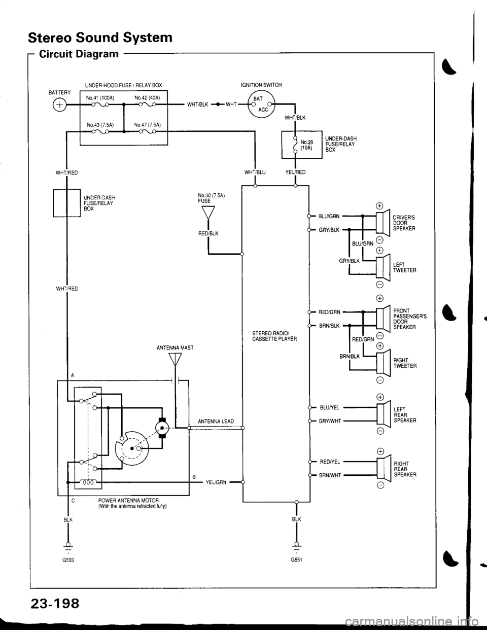
Stereo Sound System
Circuit Diagram
WHT/RED
tWHTi RED
UNDER.HOOD FUSE / RELAY BOX
UNDER.DASHFUSE/RELAYBOX
N0.30 (7.5A)FUSE
f7
IRED/BLK
UNDER,DASHFUSE/RELAYBOX
FRONTPASSENGER'SoooRSPEAKER
ANTENNA MAST
LEFTREABSPEAKER
RIGHTREARSPEAKEB
rna-ll
-ttl
;\\:/
o=4-ll
-{tl
x!\:/
ANTENNA LEAD
BLU,YEL
GRY/rrVHT
REO/YEL
ERNMHT
POWER ANTENNA MOTOR{wilh lhe antenna reraded lully)
BLK
I
G551
8LK
I
G503
No 4l (100A) No 42 (40A)
rc\RED/GRN VSTEBEO RADIOiCASSETTE PLAYER
23-198
Page 1256 of 1681
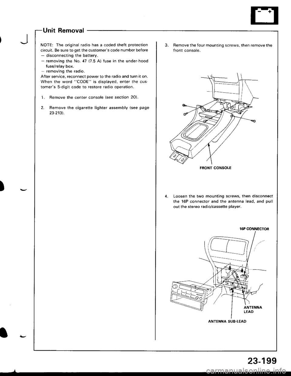
Unit Removal
NOTE: The original radio has a coded thelt protection
circuit. Be sure to get the customer's code number before- disconnecting the battery.- removing the No. 47 (7.5 A) fuse in the under-hood
fuse/relay box.- removing the radio.
After service. reconnect power to the radio and turn it on.
When the word "CODE" is displayed, enter the cus-
tomer's 5-digit code to restore radio operation.
'1. Remove the center console (see section 20).
2. Remove the cigarette lighter assembly (see page
23-2131.
)
FRONT CONSOLE
Remove the four mounting screws, then remove the
front console.
Loosen the two mounting screws. then disconnect
the 16P connector and the antenna lead, and Dull
out the stereo radio/cassette plaver.
16P CONNECTOR
ANTENNA SUB-LEAD
23-199
Page 1263 of 1681
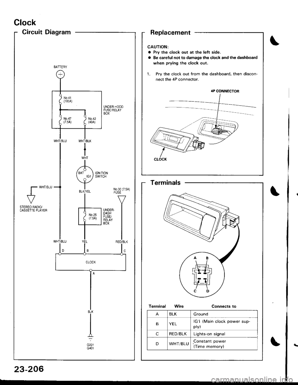
Clock
CircuitDiagram
CAUTION:
a Prv the clock out at the left side.
a Be careful not to damage the clock and the dashboard
when prying the clock out.
1. Pry the clock out from the dashboard. then discon-
nect the 4P connector.
4P CONNECTOR
CLOCK
BATTERY
UNDER,HOODFUSE/RELAYBOX
WI-]T/BLK
I
A/ BAT I 1GN TION
Y*"t No3o(7.sA)-|" -v
F'nrrn l
I
WHT/BLU
l- wHT 8LU
al-
STEREO BADIOiCASSETTE PLAYEF
BLK
G201G401
BLKGround
BYELrG1
pry,
(Main clock power sup-
cRE D/BLKLights-on signal
DWHT/BLUConstant power
(Time memory)
Terminals
23-206
Page 1264 of 1681
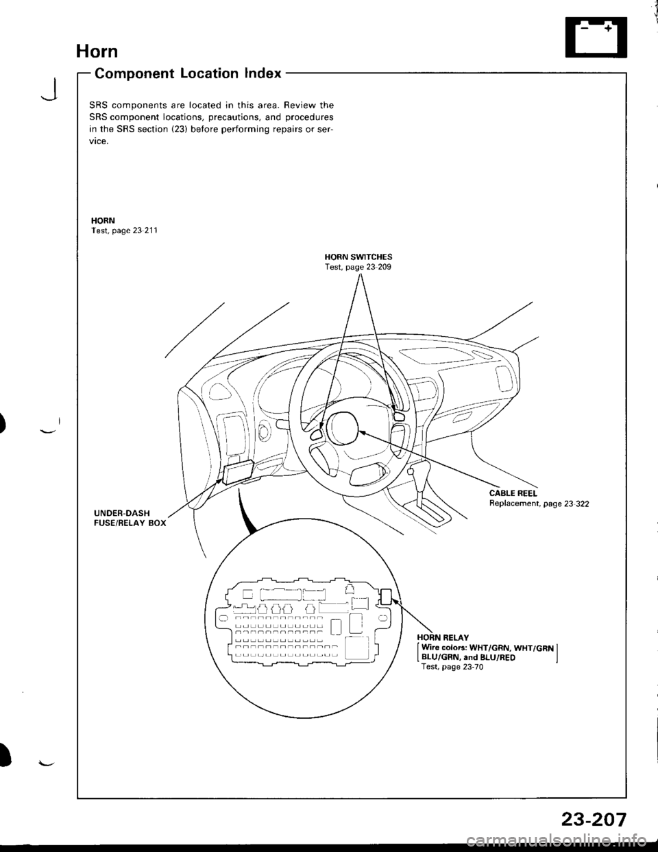
Horn
Component Location lndex
JSRS components are located in this area. Review the
SRS component locations, precautions, and procedures
in the SRS section {23) before performing repairs or ser-
vtce,
HORNTest, page 23 211
HORN SWITCHESTest, page 23-209
CABLE REELReplacement, page 23 322UNDER-DASHFUSE/BELAY BOX
{---=-\s":=',-i=
il
-rrj _LJLi lJJJ I -.r ----------;- - t--t -----,------- L I t---HORN RELAY
I Wire colo6: WHT/GRN, WHT/GRN ILBLU/GRN, and BLU/REO ITest, page 23-70
)
23-207
Page 1266 of 1681
SwitchTest
SRS comDonents are located in this area. Review the
SRS component locations, precautions, and procedures
in the SRS section (23) before performing repairs or ser-
vtce.
NOTE: The original radio has a coded thett protection cir-
cuit. Be sure to get the customer's code number beJore- disconnecting the battery.- removing the No. 47 (7.5 A) fuse from the under-hood
fuse/relay box.- removing the radio.
After service, reconnect Dower to the radio and turn it on.
When the word "CODE" is displayed, enter the customer's
5-digit code to restore radio operation
Disconnect the battery negative cable, then discon-
nect the positive cable, and wait at least three min-
uIes.
Disconnect each airbag connector.
Driver's Side:
a Remove the access panel from the steering wheel,
then disconnect the 2P connector between the
driver's airbag and cable reel.
Front Passenger's Side:
. Remove the glove box,
a Disconnect the 2P connector between the front
passenger's airbag and SRS main harness.
1.
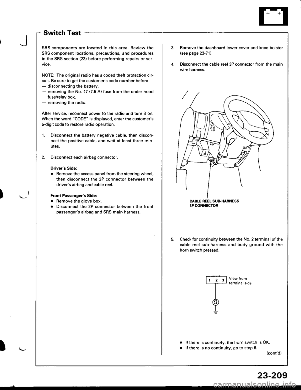
Remove the dashboard lower cover and knee bolster(see page 23-71).
Disconnect the cable reel 3P conneclor from the main
wtre narness.
CABLE REEL SUB.HARNESS3P CONNECTOR
Check for continuitv between the No. 2 terminal of the
cable reel sub-harness and body ground with the
horn switch Dressed.
terminalside
a
It there is continuity, the horn switch is OK.
lf there is no continuity, go to step 6. (cont,d)
r-P r11 2 3l-t-
I
I\-J
)
I
23-209
Page 1270 of 1681
J
)
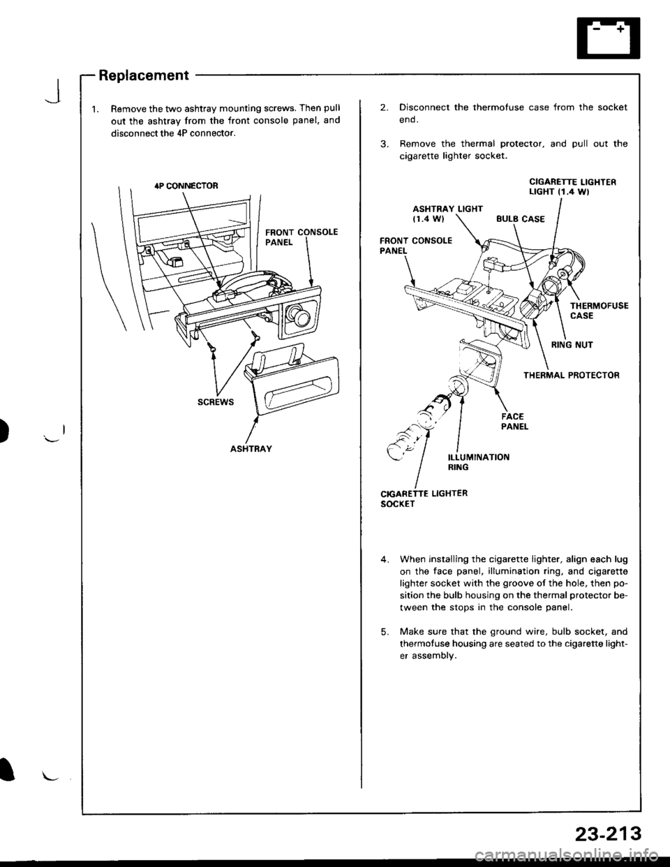
1.Remove the two ashtray mounting screws. Then pull
out the ashtray from the front console panel. and
disconnect the 4P connector.
2.Disconnect the thermofuse case from the
end.
Remove the thermal protector, and pull
cigarette lighter socket.
socket
out the
CIGARETTE LIGHTERLTGHT t1.4 Wl
ASHTRAY LIGHTt1.4 WlEULB CASE
FRONT CONSOLEPANEL
THERMOFUSECASE
RING NUT
THERMAL PROTECTOR
scREws
ILLUMINATIONRING
CrcANETTE LIGHTERsocxET
When installing the cigarette lighter, align each lug
on the face panel, illumination ring, and cigarette
lighter socket with the groove of the hole. then po-
sition the bulb housing on the thermal protector be-
tween the stops in the console panel.
Make sure that the ground wire, bulb socket, and
thermofuse housing are seated to the cigarette light-
er assembly.
5.
ASHTRAY
l\-
23-213
Page 1271 of 1681
Rear Window Defogger
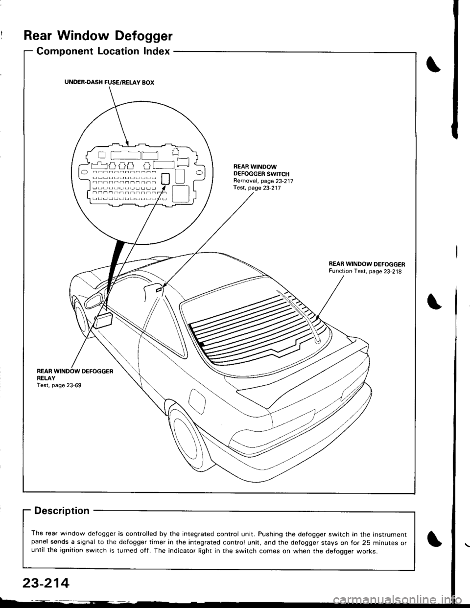
Component Location Index
Description
The rear window de{ogger is controlled by the integrated control unit. Pushing the detogger switch in the Instrumentpanel sends a signal to the defogger timer in the integrated control unit, and the defogger stays on for 25 minutes oruntil the ignition switch is turned off. The indicator light in the switch comes on when the defogger works.
UNDER.OASH FUSE/RELAY BOX
r-'luijij u lNEAR WINDOWDEFOGGER SWITCHRemoval, page 23-217Test, page 23 217
REARDEFOGGERREI-AYTest, page 23-69
23-214
Page 1272 of 1681
![HONDA INTEGRA 1998 4.G Workshop Manual Circuit Diagram
REARwtNDowDEFOGGERSWITCH
BLK
IIJ
DASH LIGHTSBR CHTNESSCONTROLLER
CN TIONswrTcH
/ 8AT \
T ",7-l
II
II
WNT/BLK + WHT
REARWiNDOWDEFOGGER
BtK/GRN
--lELKGRN BLI(RED
1A
T L-]
ll
tl
tl
tl-l
U HONDA INTEGRA 1998 4.G Workshop Manual Circuit Diagram
REARwtNDowDEFOGGERSWITCH
BLK
IIJ
DASH LIGHTSBR CHTNESSCONTROLLER
CN TIONswrTcH
/ 8AT \
T ",7-l
II
II
WNT/BLK + WHT
REARWiNDOWDEFOGGER
BtK/GRN
--lELKGRN BLI(RED
1A
T L-]
ll
tl
tl
tl-l
U](/img/13/6069/w960_6069-1271.png)
Circuit Diagram
REARwtNDowDEFOGGERSWITCH
BLK
IIJ
DASH LIGHTSBR CHTNESSCONTROLLER
CN TIONswrTcH
/ 8AT \
T ",7-l
II
II
WNT/BLK + WHT
REARWiNDOWDEFOGGER
BtK/GRN
--lELKGRN BLI(RED
1A
T L-]
ll
tl
tl
tl-l
UNDEF HOOD FUSE/RELAY BOX
No41 (100A) N0.42 (40A)
G201G401G201G40lHatchback:G771Sedan iG503I
23-215
Page 1277 of 1681
![HONDA INTEGRA 1998 4.G Workshop Manual Moonroof
Circuit Diagram
\,
UNDER,HOOD FUSEi RELAY 8OX
No 41 (100A) N0.42 (40A)
IGNIT ON SW]TCH
M
MOONROOF M0TOR (Harchback)
BLK
G201G401
MOONROOF M0TOR (Sedan)
23-220 HONDA INTEGRA 1998 4.G Workshop Manual Moonroof
Circuit Diagram
\,
UNDER,HOOD FUSEi RELAY 8OX
No 41 (100A) N0.42 (40A)
IGNIT ON SW]TCH
M
MOONROOF M0TOR (Harchback)
BLK
G201G401
MOONROOF M0TOR (Sedan)
23-220](/img/13/6069/w960_6069-1276.png)
Moonroof
Circuit Diagram
\,
UNDER,HOOD FUSEi RELAY 8OX
No 41 (100A) N0.42 (40A)
IGNIT ON SW]TCH
M
MOONROOF M0TOR (Harchback)
BLK
G201G401
MOONROOF M0TOR (Sedan)
23-220
Page 1279 of 1681
Moonroof
Function Test
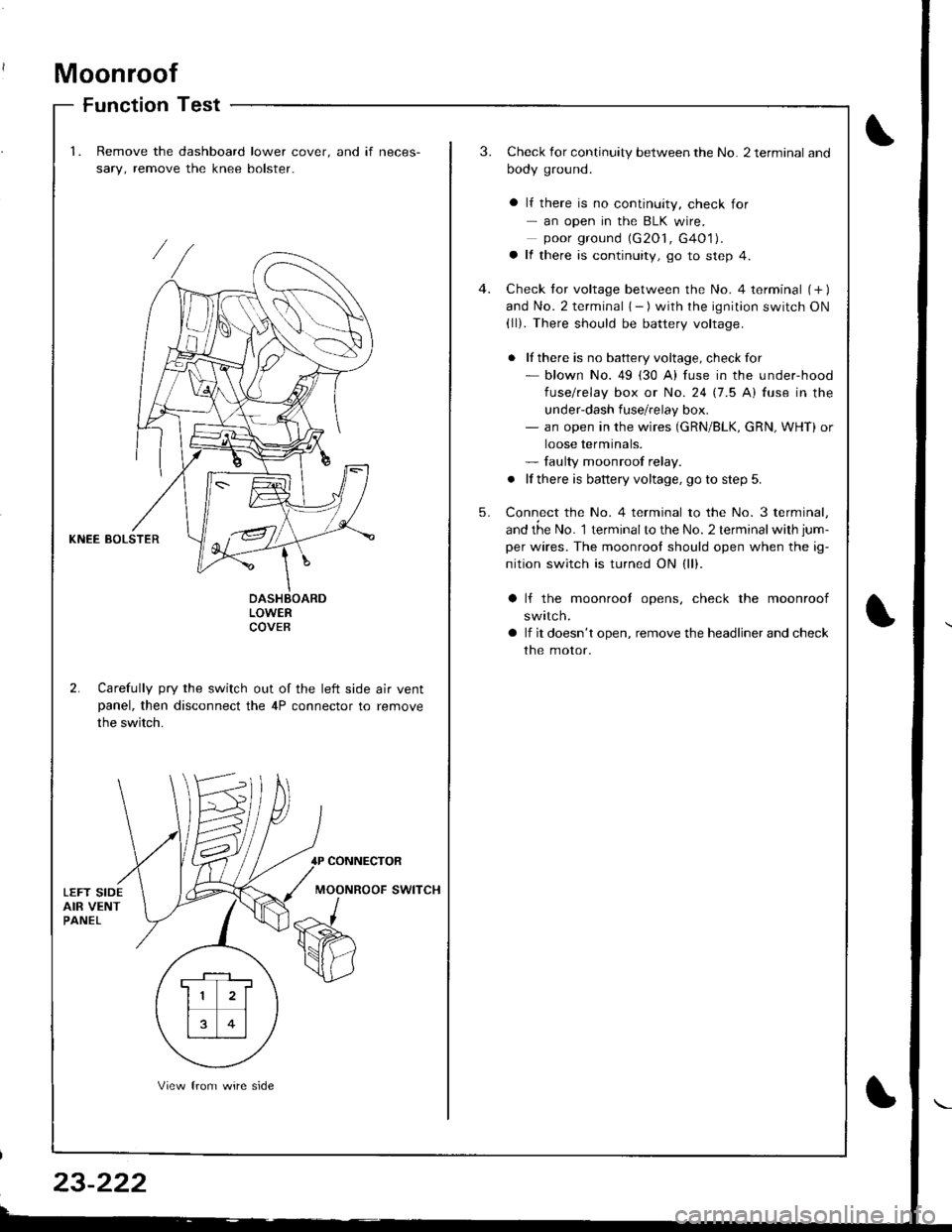
1.Remove the dashboard lower cover. and if neces-
sary, remove the knee bolster.
3.Check for continuity between the No. 2 terminal and
body ground.
a lf there is no continuity, check for- an open in the BLK wire.poor ground (G2O1, G4O1).a lf there is continuity, go to step 4.
Check tor voltage between the No. 4 terminal (+ )and No. 2 terminal { - ) with the ignition switch ON(ll). There should be battery voltage.
. lf there is no battery voltage, checkfor- blown No. 49 (30 A) fuse in the under-hood
fuse/relay box or No. 24 17.5 Al fuse in the
under-dash fuse/relay box.- an open in the wires (GRN/BLK, cRN, WHT) or
loose terminals.- faulty moonroof relay.
. lf there is battery voltage, go to step 5.
Connect the No. 4 terminal to the No. 3 terminal,
and the No. 1 terminalto the No. 2 terminal with jum-
per wires. The moonrool should open when the ig-
nition switch is turned ON (ll).
4.
5.
KNEE BOLSTER
LOWERCOVEB
2. Carefully pry the switch out of the left side air ventpanel, then disconnect the 4P connector to remove
the switch.
lf the moonrool opens, check the moonroof
swttcn.
lf it doesn't open, remove the headliner and check
the motor.
CONNECTOR
MOONROOF SWITCH
. F-_1 ,
11 2l
rt�1
13 0l
View from wire side