radio antenna HONDA INTEGRA 1998 4.G Workshop Manual
[x] Cancel search | Manufacturer: HONDA, Model Year: 1998, Model line: INTEGRA, Model: HONDA INTEGRA 1998 4.GPages: 1681, PDF Size: 54.22 MB
Page 949 of 1681
Dashboard
Component Removal/lnstallation (cont'dl
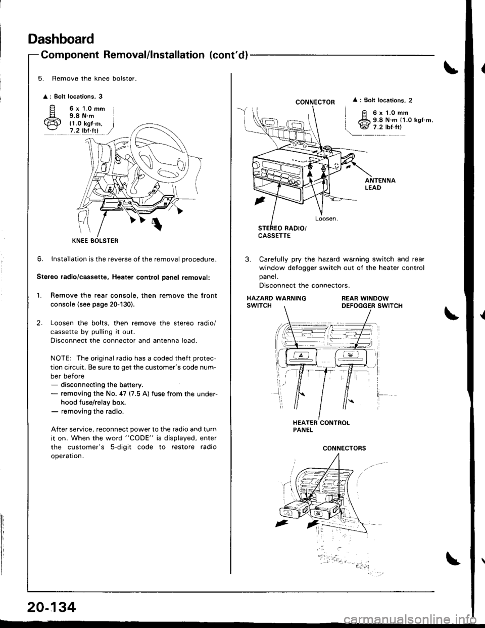
5. Remove the knee bolster.
: Bolt
A'ir
locations,3
6 x 1.0 mm9.8 N.m
{1.0 kgt m,7.2 tbf.fit
0
6. lnstallation is the reverse o{ the removal procedure.
Ste.eo ladio/cassette, Heatet contlol Danel removal:
1. Remove the rear console, then remove the front
console (see page 20-130).
Loosen the bolts, then remove the stereo radio/
cassette by pulling it out.
Disconnect the connector and antenna lead.
NOTEr The original radio has a coded theft protec-
tion circuit. Be sure to get the customer's code num-
ber before- disconnecting the battery.- removing the No. 47 (7.5 A) tuse from the under-
hood fuse/relay box.- removing the radio,
After service, reconnect power to the radio and turn
it on. When the word "CODE" is displayed, enter
the customer's 5-digit code to restore radio
ope.ation.
KNEE BOLSTER
20-134
CONNECTOR
CASSETTE
: Bolt locations, 2
6x1.0mm9.8 N.m {1.0 kgt m,
3. Carefully pry the hazard warning switch and rear
window detogger switch out of the heater control
panel.
Disconnect the connectors.
HAZARD WARNINGswtTcHREAR WINDOWDEFOGGER SWITCH
CONNECTORS
Page 1253 of 1681
Stereo Sound System
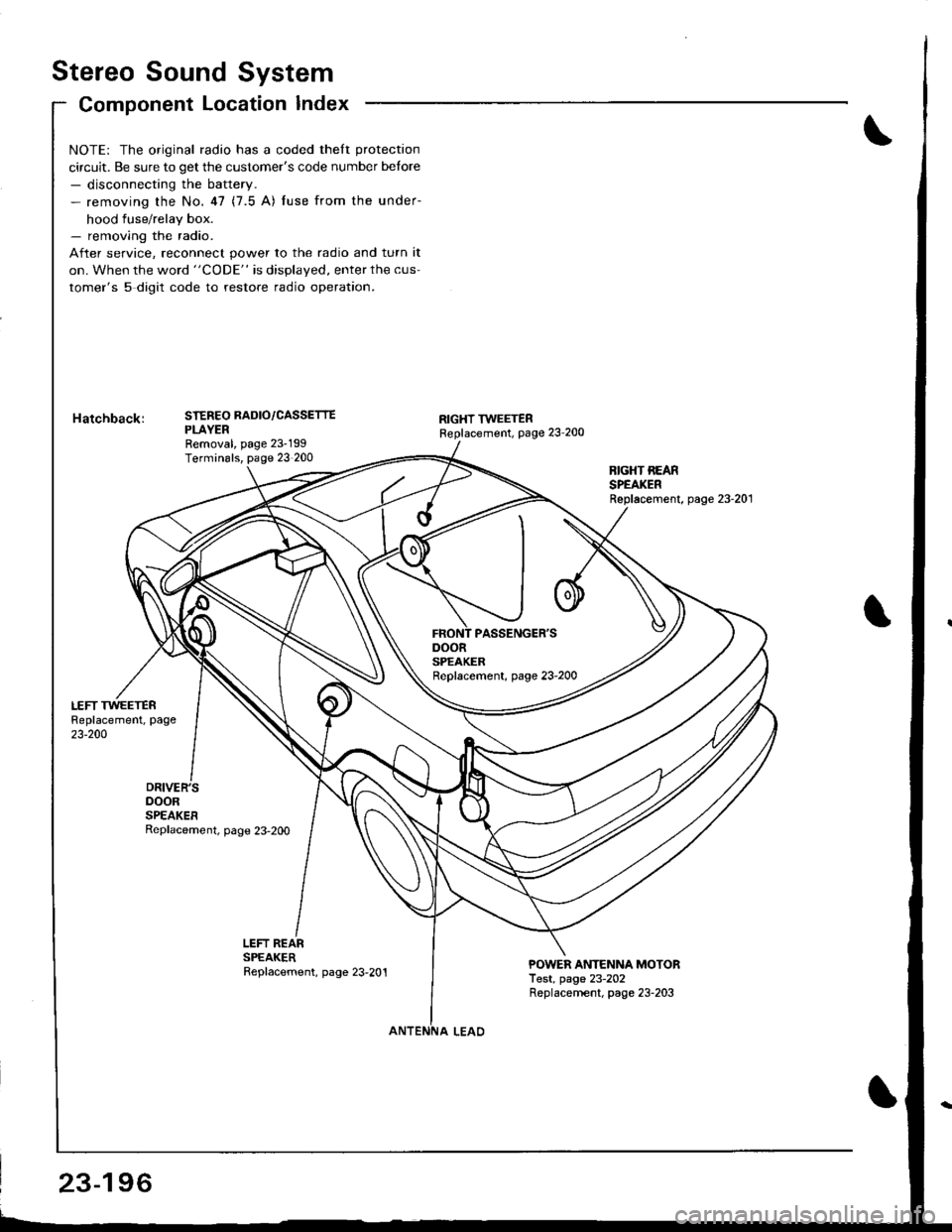
Component Location Index
DOORSPEAKERReplacement, page 23-2OO
NOTE: The original radio has a coded theft protection
circuit. Be sure to get the customer's code number betore- disconnecting the battery.- removing the No.47 (7.5 A) fuse from the under-
hood fuse/relay box.- removing the radio.
After service, reconnect power to the radio and turn it
on. When the word "CODE" is displayed, enter the cus-
tomer's 5 digit code to restore radio operation.
STEREO RADIO/CASSETTEPLAYERRemoval, page 23-199Terminals, page 23 200
RIGHT TWEETERReplacement, page 23'200
BIGHT REARSPEAKERReplacement, page 23-201
LEFT REARSPEAKERReplacement, page 23,201POWER ANTENNA MOTORTest, page 23-202Replacernent, page 23-203
23-196
Page 1254 of 1681
Sedan:
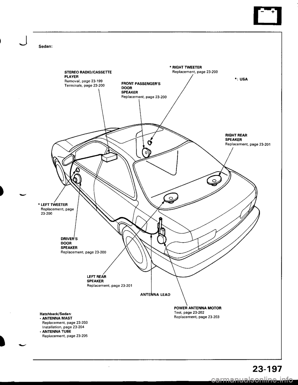
STEREO RADIO/CASSETTEPLAYERRemoval, page 23'199Terminals, page 23-200
DRIVER'SDOORSPEAKERReplacement, page 23-200
FRONT PASSENGER'SooonSPEAKERBeplacement, page 23-200
* RIGHT TWEEIERReplacement. page 23-200
POWER ANTENNA MOTORTest, page 23-202Replacement, page 23-203
*: USA
)
LEFTSPEAKERReplacement, page 23-201
Hatchback/S6dan:. ANTENNA MASTReplacement, page 23'203Installation, page 23-204. ANTENNA TUBEReplacement, page 23-205
)
23-197
Page 1255 of 1681
Stereo Sound System
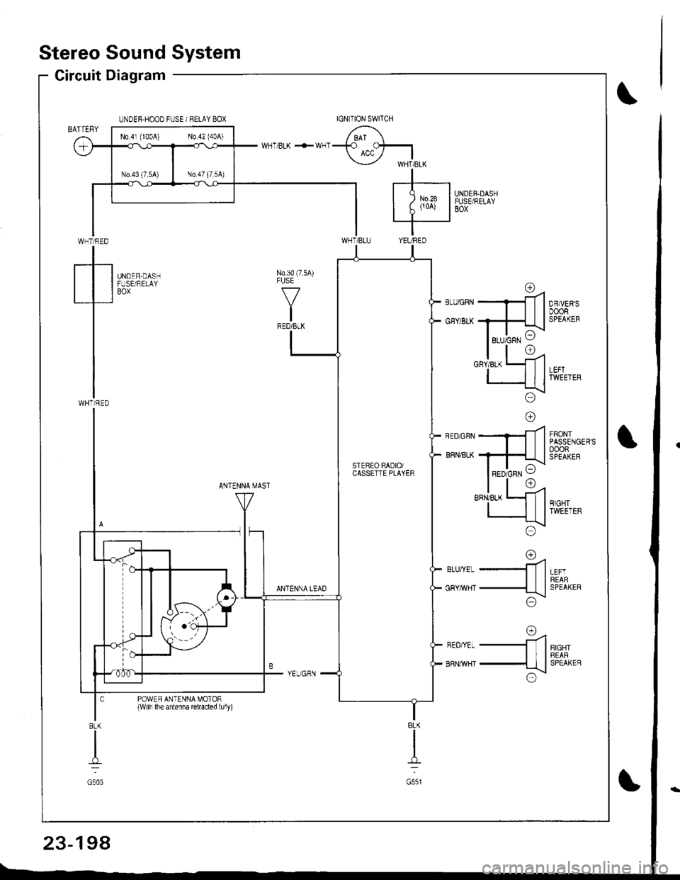
Circuit Diagram
WHT/RED
tWHTi RED
UNDER.HOOD FUSE / RELAY BOX
UNDER.DASHFUSE/RELAYBOX
N0.30 (7.5A)FUSE
f7
IRED/BLK
UNDER,DASHFUSE/RELAYBOX
FRONTPASSENGER'SoooRSPEAKER
ANTENNA MAST
LEFTREABSPEAKER
RIGHTREARSPEAKEB
rna-ll
-ttl
;\\:/
o=4-ll
-{tl
x!\:/
ANTENNA LEAD
BLU,YEL
GRY/rrVHT
REO/YEL
ERNMHT
POWER ANTENNA MOTOR{wilh lhe antenna reraded lully)
BLK
I
G551
8LK
I
G503
No 4l (100A) No 42 (40A)
rc\RED/GRN VSTEBEO RADIOiCASSETTE PLAYER
23-198
Page 1256 of 1681
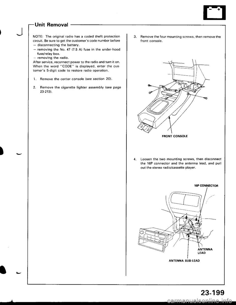
Unit Removal
NOTE: The original radio has a coded thelt protection
circuit. Be sure to get the customer's code number before- disconnecting the battery.- removing the No. 47 (7.5 A) fuse in the under-hood
fuse/relay box.- removing the radio.
After service. reconnect power to the radio and turn it on.
When the word "CODE" is displayed, enter the cus-
tomer's 5-digit code to restore radio operation.
'1. Remove the center console (see section 20).
2. Remove the cigarette lighter assembly (see page
23-2131.
)
FRONT CONSOLE
Remove the four mounting screws, then remove the
front console.
Loosen the two mounting screws. then disconnect
the 16P connector and the antenna lead, and Dull
out the stereo radio/cassette plaver.
16P CONNECTOR
ANTENNA SUB-LEAD
23-199
Page 1257 of 1681
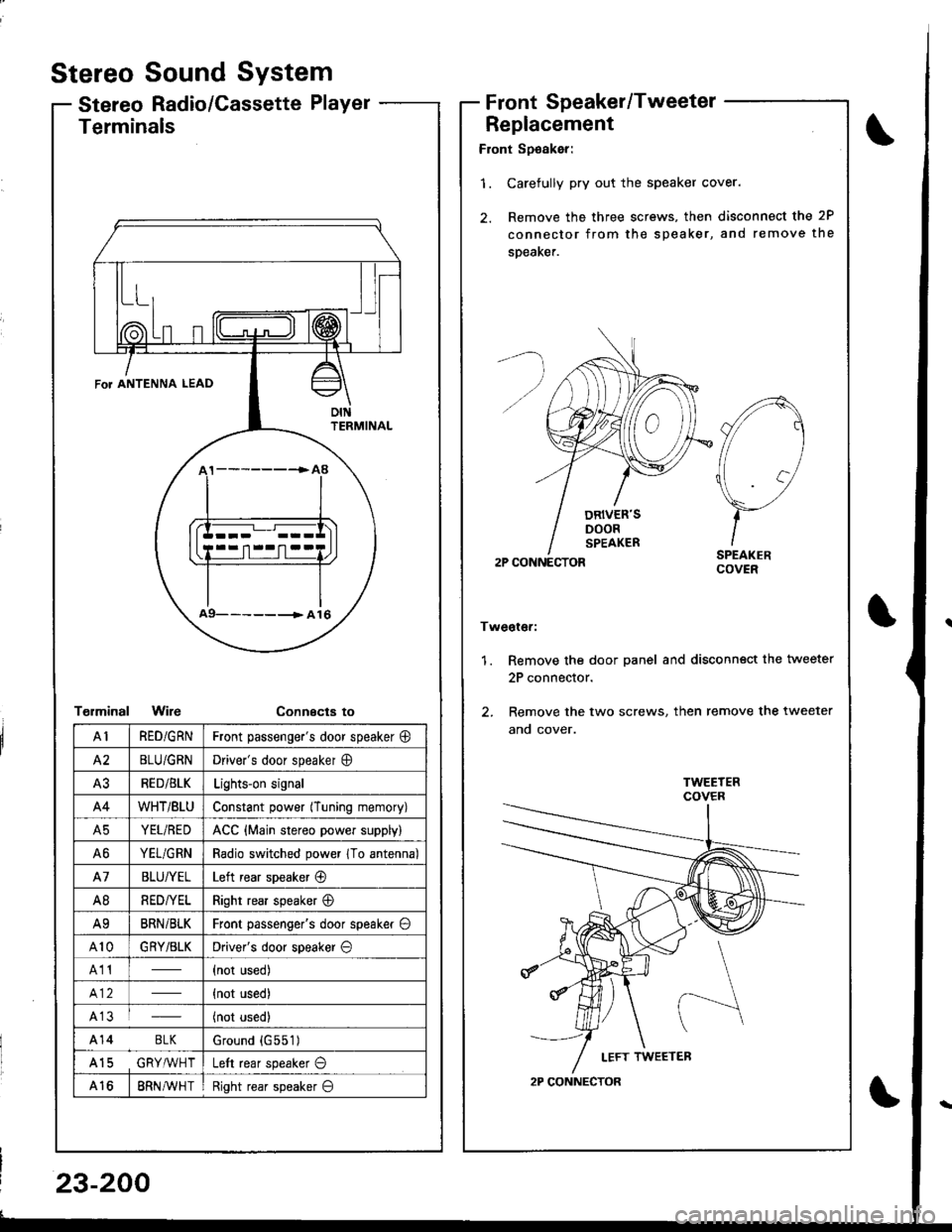
Stereo
Stereo
Sound System
Radio/Cassette PlayerFrontSpeaker/Tweeter
Replacement
Front Sp€aker:
'1. Carefully pry out the speaker cover.
2. Remove the three screws, then disconnect the 2P
connector from the speaker, and remove the
speaKer.
2P CONNECTOR
Tweoter:
1. Remove the door panel and disconn€ct the tweeter
2P connector.
2. Remove the two screws, then remove the tweeter
ano cover.
A
//1
\7
)-ISPEAKERCOVER
2P CONNECTOR
Terminals
T€rminalWireConnecta to
\
FoT ANTENNA LEAD
oIttFRMINAL
a9- -- -------> A 16
AIRED/GRNFront passenge.'s door speaker @
A2BLU/GRNDriver's door speaker O
A3RED/BLKLights-on signal
A4WHT/BtUConstant power (Tuning memory)
A5YEL/REDACC {Main stereo power supply)
A6YEL/GRNRadio switched power 1To antenna)
A7BLU/YELLeft rear speaker @
A8RED/YELRight rear speaker @
A9BRNi BLKFront passenger's door speaker O
A10GRY/BLKDriver's door speaker O
A11(not used)
{not used)
A13(not used)
A14 BLKGround {G551)
A15 GRY,ryVHTLeft rear speaker O
A168RN AVH TRight rear speaker O
23-200
Page 1259 of 1681
3.
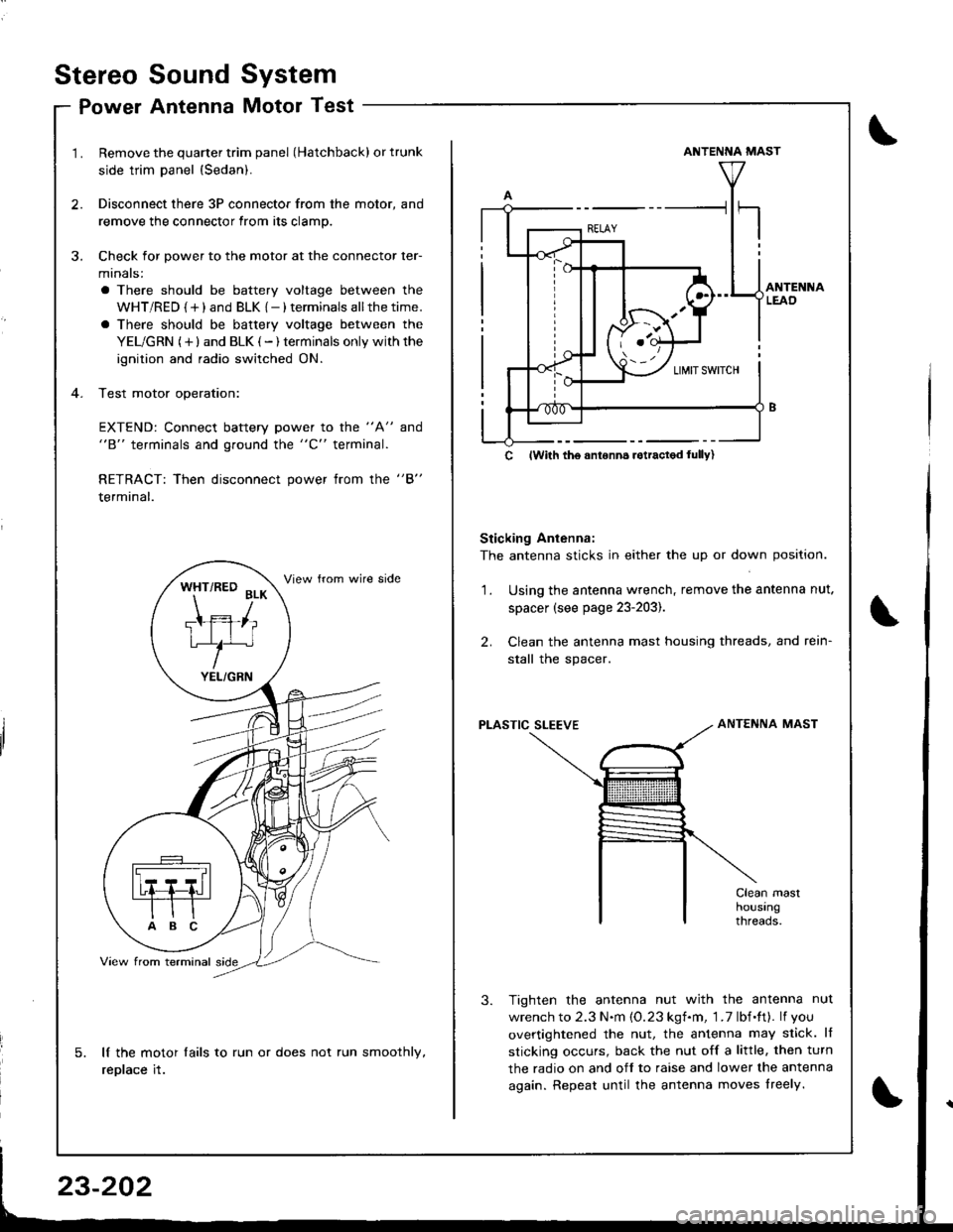
1.
wel
Remove the quarter trim panel (Hatchback) or trunk
side trim panel {Sedan).
Disconnect there 3P connector from the motor, and
remove the connector from its clamp.
Check for power to the motor at the connector ler-
minals:
a There should be battery voltage between the
WHT/RED {+) and BLK {-) terminals allthetime.
a There should be battery voltage between the
YEL/GRN (+) and BLK (-) terminals only withthe
ignition and radio switched ON.
Test motor operation:
EXTEND: Connect battery power to the "A" and"B" terminals and ground the "C" terminal.
RETRACT: Then disconnect power from the "B"
terminal.
lf the motor lails to run or does not run smoothly,
replace it.
WHT/RED BLK
Ttffiliu/^
YEL/GRN
ANTENNA MAST
Sticking Antenna:
The antenna sticks in either the up or down position.
Using the antenna wrench, remove the antenna nut.
spacer (see page 23-203).
Clean the antenna mast housing threads, and rein-
stall the spacer.
2.
1.
PLASTIC SLEEVEANTENNA MAST
Tighten the antenna nut with the antenna nut
wrench to 2.3 N.m {O.23 kgf.m, 1 .7 lbf.ft}. lf you
overtightened the nut, the antenna may slick. lf
sticking occurs, back the nut off a little, then turn
the radio on and off to raise and lower the antenna
again. Repeat until the antenna moves lreely.
c lwith tho anronn6 rotractod lully)
Stereo
Po
Sound
Antenna
System
Motor Test
\
Page 1260 of 1681
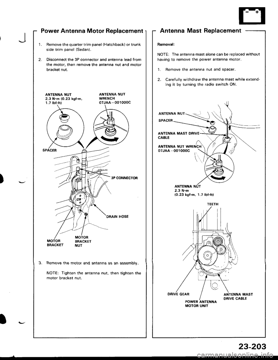
Power Antenna Motor Replacement
1.Remove the quarter trim panel (Hatchbackl or trunk
side trim panel (Sedanl.
Disconnect the 3P connector and antenna lead from
the motor. then remove the antenna nut and motor
bracket nut.
2.
ANTENNA NUT2.3 N.m {0.23 kgf'm,1.7 tbf.trt
3P CONNECTOR
DRAIN HOSE
3.Remove the motor and antenna as an assembly.
NOTE: Tighten the antenna nut, then tighten the
motor bracket nut.
AntennaMastReplacement
Removal:
NOTE: The antenna mast alone can be replaced without
having to remove the power antenna motor.
1. Remove the antenna nut and spacer.
2. Carefully withdraw the antenna mast while extend-
ing it by turning the radio switch ON.
ANTENNA NUT
SPACER
ANTENNA MAST DRIVECABLE
\..
ANTENNA NUT WRENCH07JAA-001000C
2.3 N.m(0.23 kgf.m, 1.7 lbf.ftl
POWER ANTENNAMOTOF UNIT
J
)
I
23-203
Page 1261 of 1681
Stereo Sound System
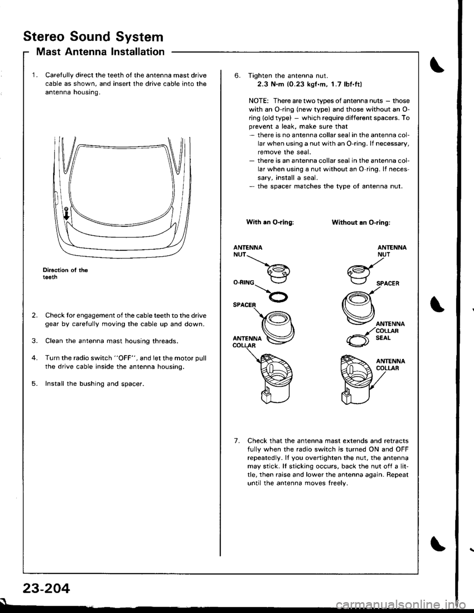
Mast Antenna Installation
Carelully direct the teeth of the antenna mast drive
cable as shown, and insert the drive cable into the
antenna housino.
Diroction ol th6teeth
Check for engagement of the cable teeth to the drive
gear by caretully moving the cable up and down.
Clean the antenna mast housing threads.
Turn the radio switch "OFF", and let the motor pull
the drive cable inside the antenna housing.
Install the bushing and spacer.
23-204
s
6. Tighten the antenna nut.
2.3 N.m (0.23 kgf .m. 1.7 lbf.ftl
NOTE: There are two types of antenna nuts - those
with an O-ring (new type) and those without an O-
ring (old type) - which require different space.s. To
prevent a leak, make sure that- there is no antenna collar seal in the antenna col-
lar when using a nut with an O-ring. lf necessary,
remove the seal.- there is an antenna collar sealin the antenna col-
lar when using a nut without an O-ring. It neces-
sary, install a seal.- the spacer matches the type of antenna nut.
With an O-ring:
ANTENNANUT__.\
a€^1.i*-lr
O-RING
Without an O-ring:
ANTENNA
ANTENNANUT
6d{.i*-.-r
SPACER
(Q\
Vorr.""o
_/coLrjlR
6 t'o'-
Check that the antenna mast extends and retracts
fully when the radio switch is turned ON and OFF
repeatedly. ll you overtighten the nut, the antenna
may stick. lf sticking occurs. back the nut of{ a lit-
tle, then raise and lower the antenna again. Repeat
until the antenna moves freely.
7.
Page 1404 of 1681
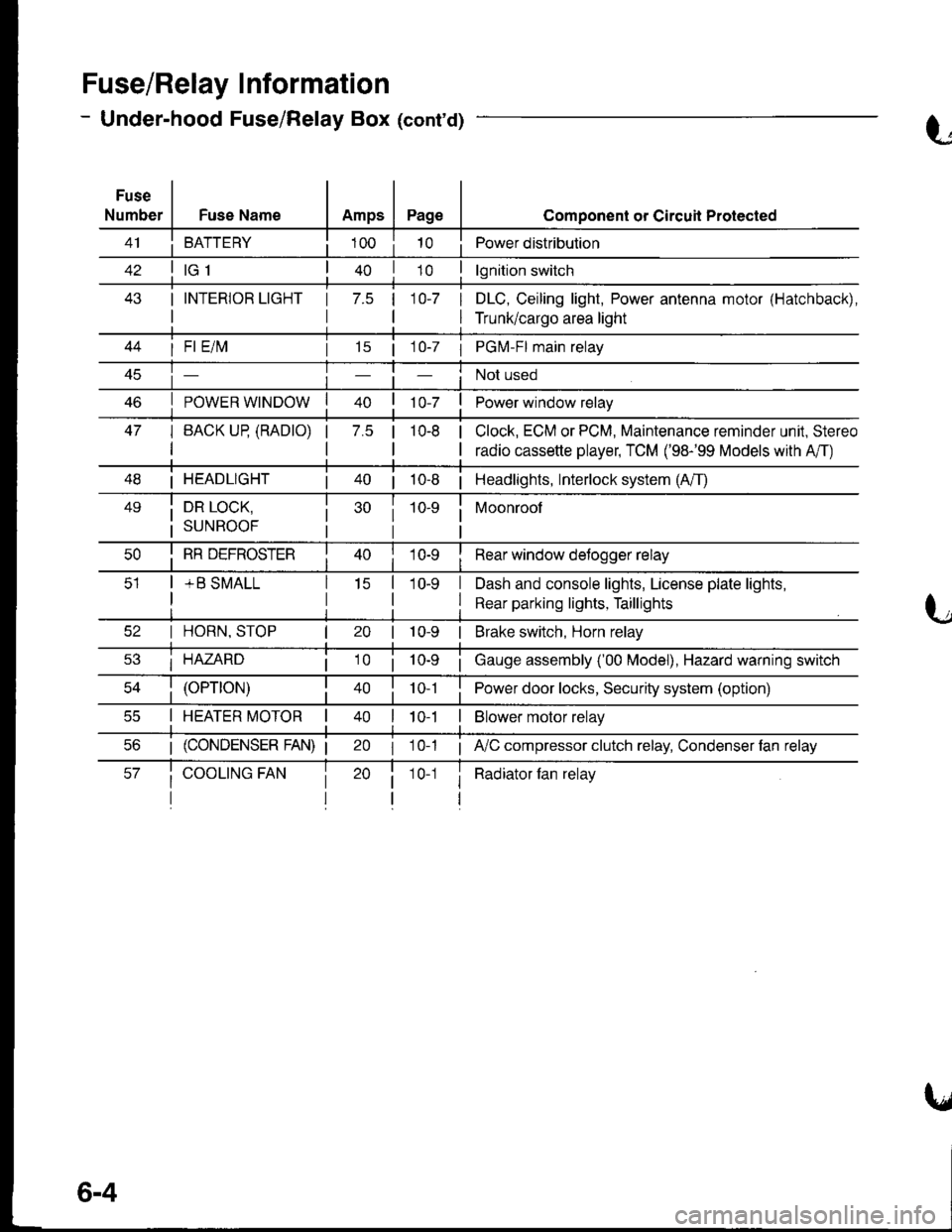
Fuse/Relay I nformation
- Under-hood Fuse/Relay Box (cont'd)
Fuse
NumberFuse NameAmpsPage
BATTERY
I INTERIOR LIGHT
I
1 7.5 110-7 I
I
Component or Circuil Protected
Power distribution
lgnition switch
DLC, Ceiling light, Power antenna motor (Hatchback),
Trunk/cargo area light
47
I Fl E/lvl
POWER WINDOW
I BACK UP (RADTO)
I
15 | 1 0-7 I PGM-FI main relay
Not used
Power window relay
Clock, ECM or PCM, Maintenance reminder unit, Stereo
radio cassette player, TCM ('98-'99 Models with A'/T)
7.5 |10-8
I HEADLIGHT| 40 | 10-8 | Headlights, Interlock system (A/T)
49i DR LOCK,
i suNRooF
10-9 i Moonroof
I
I RR DEFROSTER
+ B SMALL
I Rear window detogger relay
I Dash and console lights, License plate lights,
I Rear parking lights, Taillights
I HORN, STOP
i HAZARD
10-9 | Brake switch, Horn relay
i Gauge assembly ('00 Model), Hazard warning switch
40 | to t I Power door locks, Security system (option)
I HEATER MOTOR II t 0-1I Blower motor relay
20 I 10-1 ; A,/C compressor clutch relay, Condenser fan relay
i Radiator fan relay1 0-1
6-4