steering HONDA INTEGRA 1998 4.G Owners Manual
[x] Cancel search | Manufacturer: HONDA, Model Year: 1998, Model line: INTEGRA, Model: HONDA INTEGRA 1998 4.GPages: 1681, PDF Size: 54.22 MB
Page 1373 of 1681
I
I
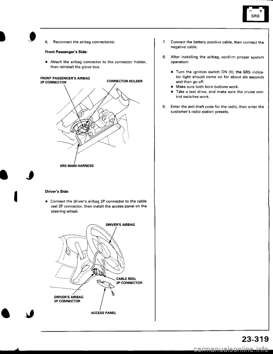
6. Reconnect the airbag connector(s).
Front Passenger's Side:
. Attach the airbag connector to the connector holder.
then reinstallthe glove box.
CONNECTOR HOLDER
Driver's Side:
. Connect the driver's airbag 2P connector to the cable
reel 2P connector, then rnstall the access panel on the
steering wheel.
\,
23-319
7.Connect the baftery positive cable, then connect thenegative cable.
After installing the airbag, confirm proper system
operal|on:
. Turn the ignition switch ON (ll); the SRS indica-
tor light should come on for about six seconds
and then go off.
. Make sure both horn buttons work.
. Take a test drive, and make sure the cruise con-
trol switches work.
Enter the anti-theft code for the radio. then enter the
customer's radio station presets,
9.
Page 1376 of 1681
Cable Reel
Replacement
@ store a removed airbag with the pad sur-
tac€ up. lf the airbag is improperly stored face down,
.ccidontal dcployment could propel the unit with
.nough torce to cause serious injury.
CAUTIONT
o Carefully insp€ct the airbag belore installing it. Do
not install an airbag that shows signs of boing
dropped or improperly handled, such as dents,
cracks or deformation.
. Always disconnect the airbag connector(s) when the
harness is disconnectod.
. Do not disassemble or tamper wiih the airbag.
1. Make sure you have the anti-theft code for the radio,
then write down the frequencies for the radio's pr+
set button.
2. Disconnect the battery negative cable, then discon-
nect the positive cable from the battery. and wait at
least three minutes,
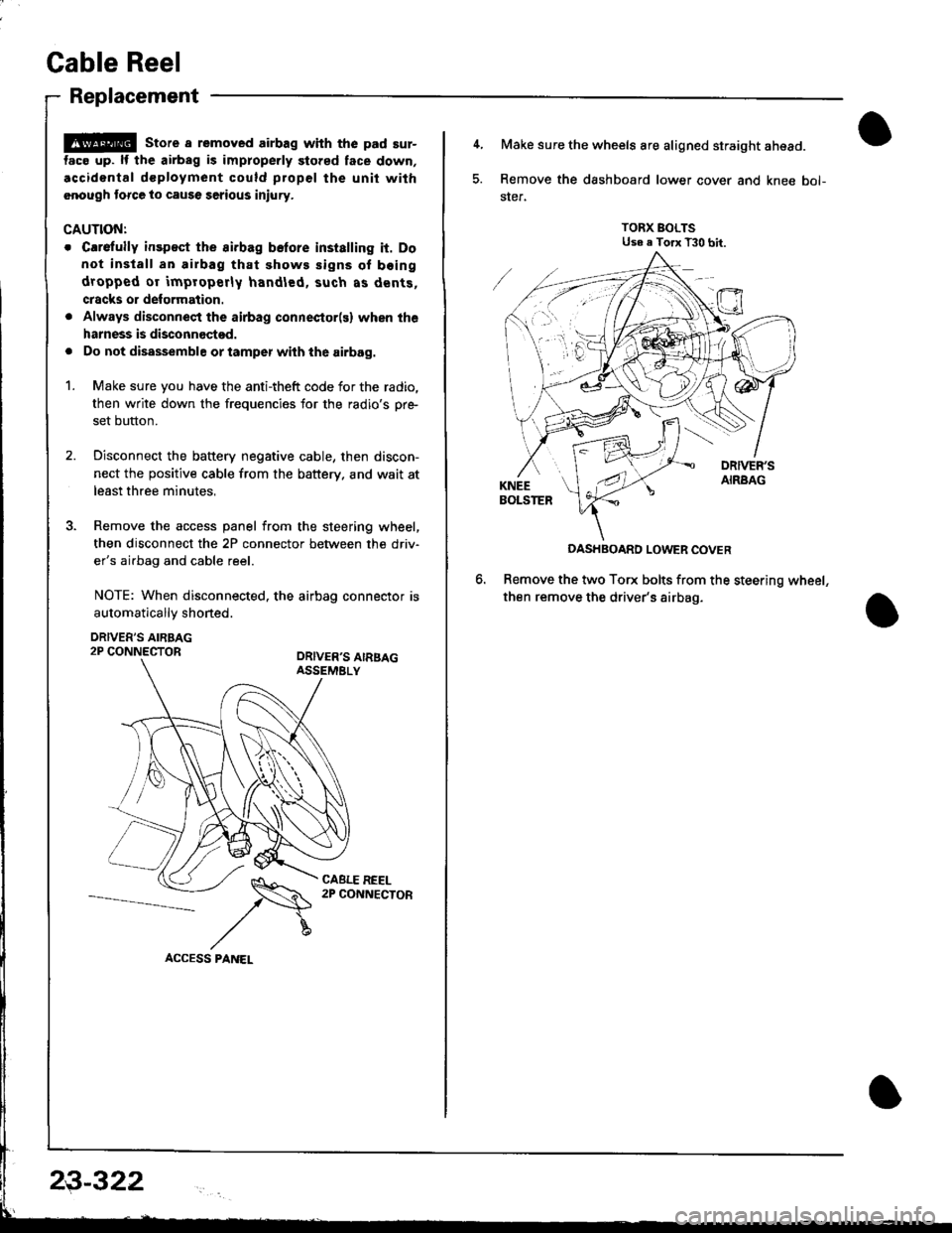
3. Remove the access panel from the steering wheel,
then disconnect the 2P connector between the driv'
er's airbag and cable reel.
NOTE: When disconnected. the airbag connector is
automaticallv shoned.
DRIVER'S AIRBAG2P CONNECTORORIVER'S AIRSAGASSEMELY
CABLE REEL2P CONNECTOR
23-322
4, Make sure the wheels are aligned straight ahead.
5. Remove the dashboard lower cover and knee bol-
ster.
TORX BOLTSUse e Torx T30 bit.
DASHBOARD LOWER COVER
Remove the two Torx bolts from the steering wheel,
then remove the driver's airbag.
Page 1377 of 1681
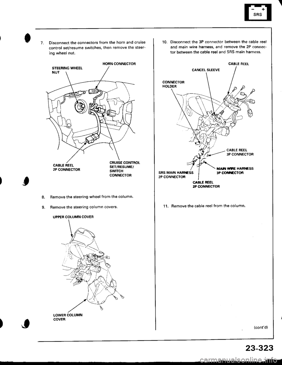
7.Disconnect the connectors from the horn and cruise
control sevresume switches, then remove the steer-
ing wheel nut.
Remove the steering wheel from the column.
Remove the steering column covers
UPPER COLUMN COVER
8.
)
HORN CONNECTOR
\
10.Disconnect the 3P connector between the cable reel
and main wire harness. and remove the 2P connec-
tor between the cable reel and SRS main harness.
CABLE BEEL
CABE R€EL2P CONNECTOR
'11. Remove the cable reel fromthecolumn.
(cont'd)
23-323
Page 1378 of 1681
Cable Reel
Replacement (cont'dl
CAUTION:
. Before installing the steering wheel, the lront
wheels should be aligned str8ight ahead.
. Be sure to install the harness wires so that they
are not pinched or interfering with other parts.
. After reassembly, confirm thal the wheels are
slill turned str8ight ahead and that the steering
wheel spoke angle is correst (road test). lf minol
spoke angle adjustment is necessary, do so only
by adiusting the tie-.ods, not by removing and
repositioning the steering wheel.
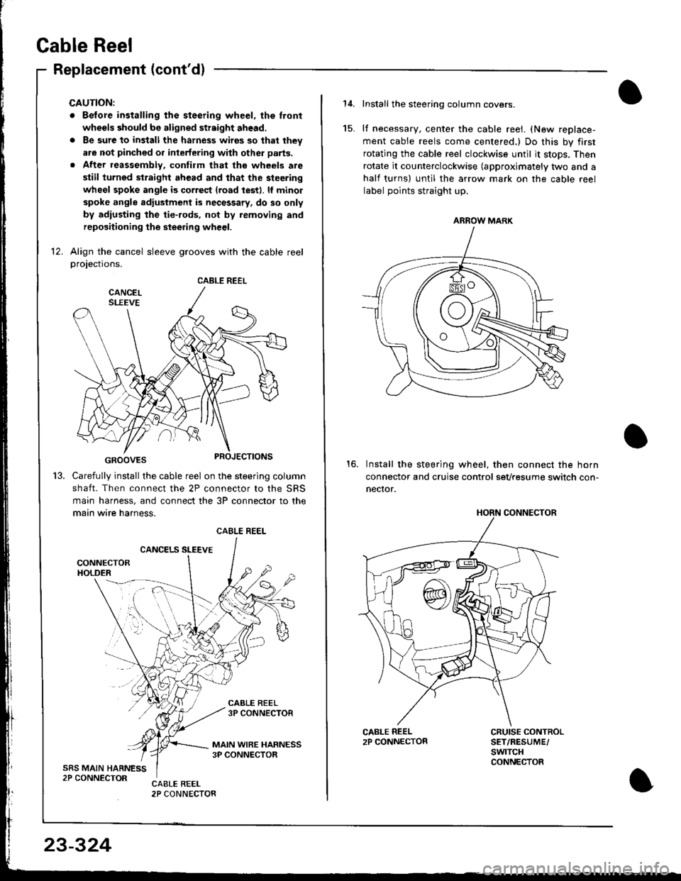
12. Align the cancel sleeve grooves with the cable reelprojections.
GROOVES
Carefully install the cable reel on the steering column
shaft. Then connect the 2P connector to the SRS
main harness, and connect the 3P connector to the
main wire harness.
CANCELS SLEEVE
CABLE REEL
13.
CABLE REEL
23-324
Install the steering column covers.
lf necessary, center the cable reei. (New replace-
ment cable reels come centered.) Do this by first
rotating the cable reel clockwise until it stops. Then
rotate it counterclockwise (approximately two and a
half turns) untll the arrow mark on the cable reel
label points straight up.
Install the steering wheel, then connect the horn
connector and cruise control sevtesume switch con-
necror.
15.
16.
CRUISE CONTROLSET/RESUME/swtTcHCONNECTOR
ARROW MARK
HORN CONNECTOR
Page 1379 of 1681
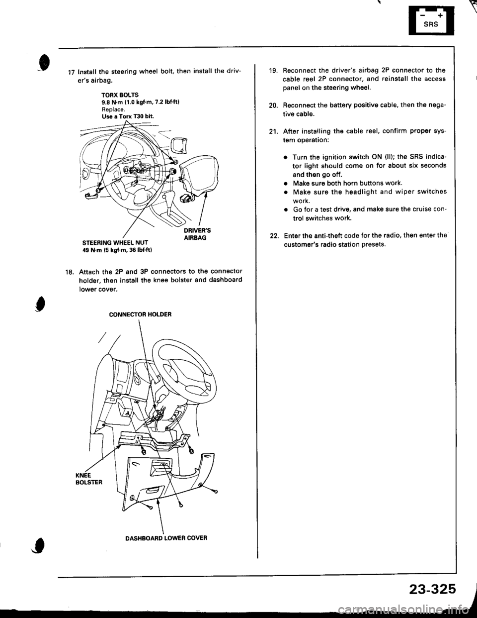
Instsll the steering wheel bolt, then install the driv-
er's airbag.
TORX BOLTS9.8 N m {1.0 kgf'm,7.2 lbtftlReplace.U3e . Torx T30 bit.
STEERING WHEEL NUT19 N.m (5 kgl.m, 36 lbl.ftl
Anach the 2P and 3P connectors to the connector
holder. then install the knee bolster and dashboard
lowgr cover,
le
CONNECTOR HOLDER
DASHBOARD LOWER COVER
23-325
\
'19. Reconnect the driver's aibag 2P connector to the
cable reel 2P connector, and reinstSll the access
panel on the steering wheel.
20, Reconnect the battery positive cable, then the nega-
tivs cable.
21. After installing the cable reel, confirm proper sys-
tgm operation:
Turn the ignition switch ON (ll); the SRS indica-
tor light should come on for about six seconds
and thsn go off.
Make surs both horn buttons work.
Make sure the headlight and wiper switches
Go {or a test drive, and make sure the cruise con-
trol switches work.
Ent6r the anti-theft code for tho radio, then enter the
customsr's radio station presets.
a
a
Page 1380 of 1681
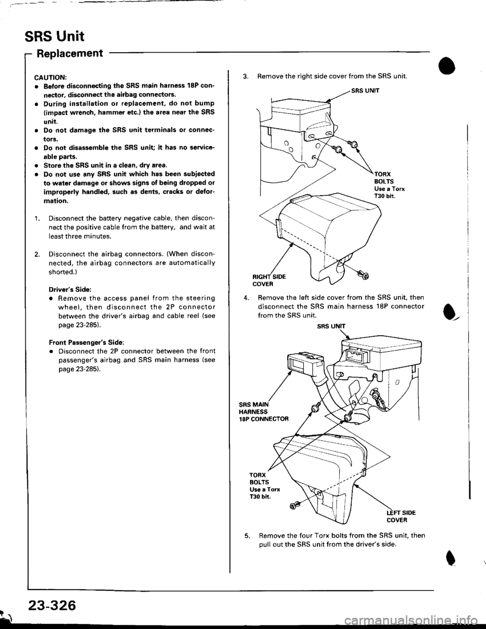
SRS Unit
Replacement
CAUNON:
. Betore disconnecting the SRS main harness 18P con-
nector, disconnect the aitbag connectors.
. During installation or replacement, do not bump
(impact wrench, hammer etc.) the al€a near the SRS
unit.
. Do not damage the SRS unit terminals or connec-
tors.
. Do not disassemble the SRS unit; it has no service-
able parts.
. Store the SRS unit in a clean, dry area.
. Do not use any SRS unit which has been subiected
to water damage or shows signs of being dtopped ol
improperly hsndled, such as dents, cracks or detor-
mation.
Disconnect the baftery negative cable, then discon-
nect the positive cable from the battery, and wait at
least three minutes.
Disconnect the airbag connectors. (When discon-
nected. the airbag connectors are automatically
shorted.)
Driver's Side:
. Remove the access panel from the steering
wheel, then disconnect the 2P connector
between the driver's airbag and cable reel (see
page 23-285).
Front Passenger's Side:
. Disconnect the 2P connector between the front
passenger's airbag and SRS main harness (see
page 23-285).
3. Remove the right side cover from the SRS unit.
SRS UNIT
TORXBOLTSUse a TorxT30 bir.
SIDEcovEn
4. Remove the left side cover from the SRS unit, then
disconnect the SRS main harness 18P connector
from the SRS unit.
sRsHARNESS18P CONNECTOR
t
TORXBOLTSU36 a ToaxT30 bh.
SIDECOVER
Remove the four Torx bolts from the SRS unit, then
pull out the SRS unit from the driver's side.
23-326?\
SRS UNIT
Page 1381 of 1681
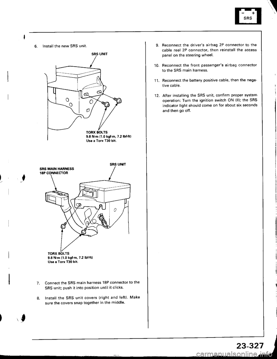
6, Install the new SRS unit.
o^ l- o
9.8 N.m 11.0 kgf m, 7.2Use a Torx T30 bit.
I
TORX BOLTS9.8 N.m 11.0 kgl.m, 7.2 lbf'ftlUse a Torx T30 bit.
7.Connect the SRS main harness l8P connector to the
SRS unit; push it into position until it clicks.
Install the SRS unit covers (right and left) Make
sure the covers snap together in the middle.8.
,l
\
10.
Reconnect the driver's airbag 2P connector to the
cable reel 2P connector, then reinstall the access
panel on the steering wheel.
Reconnect the front passenger's airbag connector
to the SRS main harness.
Reconnect the battery positive cable, then the nega-
tive cable.
After installing the SRS unit, confirm proper system
operation: Turn the ignition switch ON (ll); the SRS
indicator light should come on for about six seconds
and then go off.
11.
12.
Page 1406 of 1681
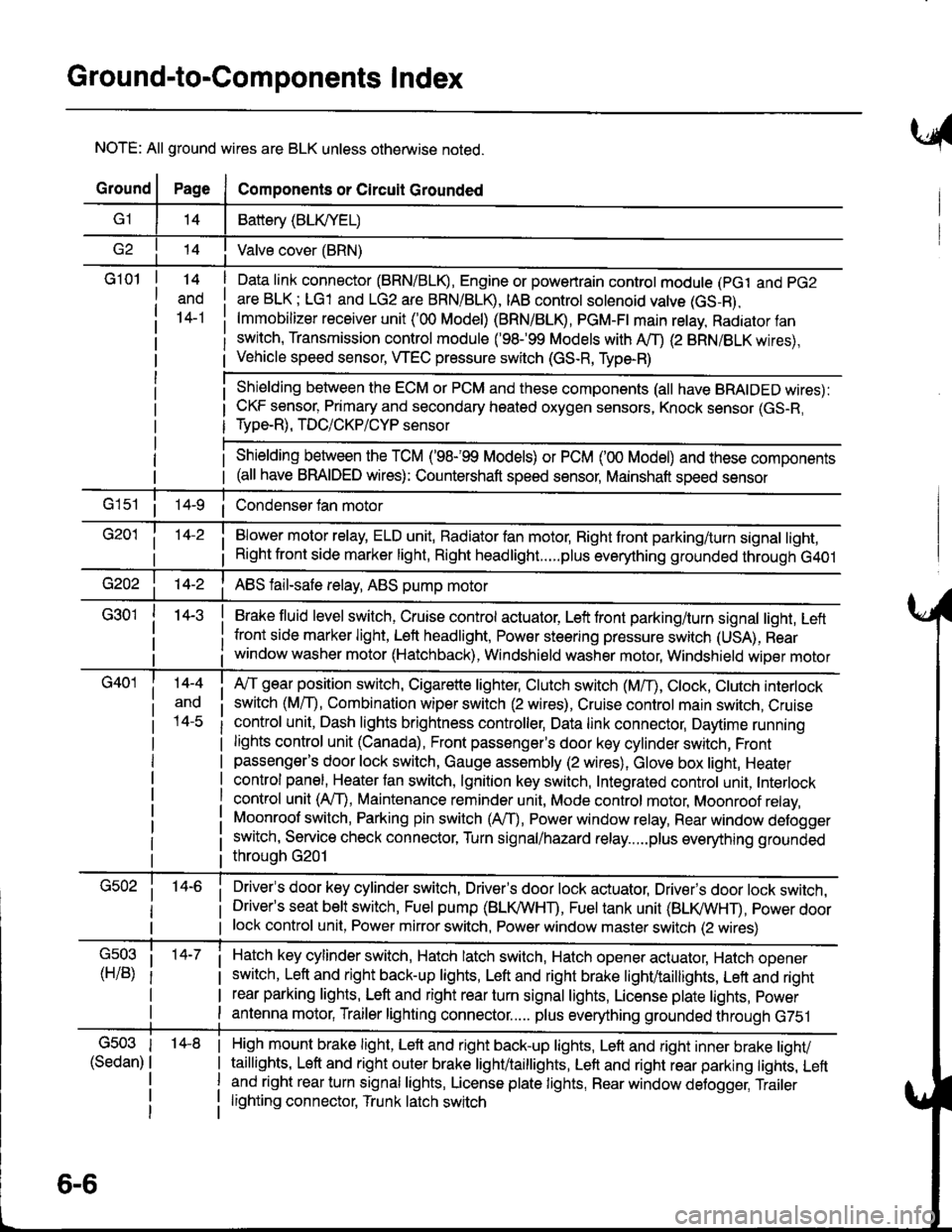
Ground-to-Components I ndex
NOTE: All ground wires are BLK unless otherwise noted.
GroundPageComponents or Circuit Grounded
Battery (BLIVYEL)
--t'I Valve cover (BRN)
G101t.+
and
14-1
Daia link connector (BRN/BLK), Engine or powertrain controt module (pct and pG2
are BLK; LG1 and LG2 are BRN/BLR, IAB controt solenoid valve (GS-B),
lmmobilizer receiver unit ('00 Model) (BRN/BLR, PGM-Ft main retay, Radiator fan
switch, Transmission control module ('98.�99 Models with MD (2 BRN/BLK wires),
Vehicle speed sensor, WEC pressure switch (GS-R, Type-R)
Shielding between the ECM or PCM and these components (all have BRAIDED wires):
CKF sensor, Primary and secondary heated oxygen sensors, Knock sensor (GS-R,
Type-R), TDC/CKP/CYP sensor
Shielding between the TCM ('98-'99 Models) or PCM ('00 Model) and these components(all have BRAIDED wires): Countershaft speed sensor, Mainshaft speed sensor
G1s1 ii Condenser fan motor
Brake fluid level switch, Cruise control actuator, Left front parking/turn signal light, Left
front side marker light, Left headlight, Power steering pressure switch (USA), Rear
window washer motor (Hatchback), Windshield washer motor, Windshield wiper motor
14-3
Blower motor relay, ELD unit, Badiator fan motor, Right front parking/turn signal light,
Right front side marker light, Right headlight.....plus everything grounded through G401
ABS fail-safe relay, ABS pump motor
G40114-4
ano
l4-c
A,/T gear position switch, Cigarette lighter, Clutch switch (M,/T), Ctock, Ctutch interlock
switch (MfD, Combination wiper switch (2 wires), Cruise control main switch, Cruise
control unit, Dash lights brightness controller, Data link connector, Daytime running
lights control unit (Canada), Front passenger's door key cylinder switch, Frontpassenger's door lock switch, Gauge assembly (2 wires), Glove box light, Heater
control panel, Heater tan switch, lgnition key switch, Integrated control unit, Interlock
control unit (AfI), Maintenance reminder unit, Mode control motor, Moonroof relay,
Moonroof switch, Parking pin switch (AfD, Power window relay, Rear window defogger
switch, Service check connector, Turn signal/hazard relay.....plus everything grounded
throuoh G201
Driver's door key cylinder switch, Driver's door lock actuator, Drivels door lock switch,Driver's seat belt switch, Fuel pump (BLI(/WHT), Fuel tank unit (BLI(/WHT), power doorlock control unit, Power mirror switch, Power window master switch (2 wires)
Hatch key cylinder switch, Hatch latch switch, Hatch opener actuator, Hatch ooener
switch, Left and right back-up lights, Left and right brake light/taillights, Lett and right
rear parking lights, Left and right rear turn signal lights, License plate lights, power
antenna motor, Trailer lighting connector..... plus everything grounded through G751
6-6
'14-8G503
(Sedan)
High mount brake light, Left and right back-up lights, Lett and right inner brake tighv
taillights, Left and right outer brake light/taittights, Left and right rear parking tights, Leftand right rear turn signal lights, License plate lights, Rear window detogger, Trailer
lighting connector, Trunk latch switch
Page 1409 of 1681
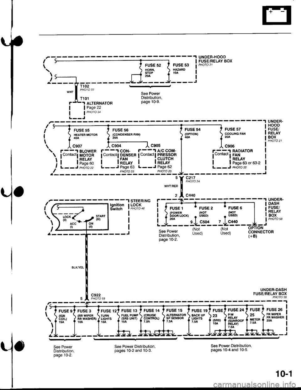
I
I
I
IJ
UNDER-HOODFUSE/RELAY BOXI
\
\.t)-
FUSE 528OFN,STOP
FUSE 53HAZARO
I'_'I ALTERNATOB
See PowerDistribution,page 10-9.
| | Pase 22
| | PHoro 31
L--J
1102
T101
FUSE 55HEATEF MOTOB
UNDEB.HOOOFUSE/RELAYBOX
FUSE 56(CoNDENSEA FAtl)204
c904
FUSE 13FUELPUTiP(sB6 UNrr)
I
I
tc907
r--'t BLowER\. tContactl MO-IOR
!ilF"'s?60RELAYI rdq€ @I L--J eudro zz
FUSE 54{oFnon)
."-'1tr;'
FUSE 57COOUNG FAX204
c9)6
r^- -:I RADIATOR
!"o"'""' ! Etto"! | Page 63 or 63.2L--J Pqofo ?2
c90s
r--1coN- r--1A'/CCOM-I Contactl DENSER I Contactl PRESSOR
! IFAN : ; CLUTCNI I RELAY I I RELAYL - - J Page 63 L--J Page 62
-- - -'l UNOER-i-
i I ruser ' rusez 'rusEo I if99Ff.
i ) &*'s"-, ,lil?l, , $?'"r I ii,At:
L -J- --- lLg%- ? J..9Yl--:1,- j
se€ Power l[:'^. l[:'^, 3!I$f"totDiskibution. ubEu/ uJcv / (+B)page 10-2.
c922
UNDER.DASHFUSE/RELAY BOXPHOfa 58
,rar ra !t#
i t FUSE st FusE 3I dcr{ rFRwtPE {tG
nn WIPEF
fis., fllo"o.".",
I
FUSE 12TUfNLIGTITSr0A
FUSE 'I5
ALlERNATOf,sP sENSoa7.tA
FUSE 19BACK UPUGHTSt.5a
FUSE 24
REIAY€rrNBooFNEIAY)?.3A
FUSE
25II€TEF7.5A
FF WPEBFA U'ASHEN204
4y--J---J
.l STEERINGI LOCK
I
I
I
J
! -l tanfiton,. ( t--) lsiwitctr
".r\l:'S7ili"'l
lf 0 ltttt I
a------rl-
l;9c* ('-' oa"t0)
--
See PowerDistribution,page 10-2.
See Power Distribution,pages 10-2 and 10-3.See Power Distribution,pages 10-4 and 10"5.
10-1
Page 1416 of 1681
![HONDA INTEGRA 1998 4.G Owners Manual Power Distribution
- From Fuses to Relays and Components (contd)
rll
FUSE 48 \HEAruCHT \{la \
II-------Jc216c217
::]:I
-..
3
ir
:l
:!, I tFUSE20, : (BUNNTNG, I I u_qHrc)
LJ___
. - All except US HONDA INTEGRA 1998 4.G Owners Manual Power Distribution
- From Fuses to Relays and Components (contd)
rll
FUSE 48 \HEAruCHT \{la \
II-------Jc216c217
::]:I
-..
3
ir
:l
:!, I tFUSE20, : (BUNNTNG, I I u_qHrc)
LJ___
. - All except US](/img/13/6069/w960_6069-1415.png)
Power Distribution
- From Fuses to Relays and Components (cont'd)
r'l'l
FUSE 48 \HEAruCHT \{la \
II-------Jc216c217
::]:I
-'..
'3
ir
:l
:!, I tFUSE20, : (BUNNTNG, I I u_qHrc)
'LJ___
. - All except USA RS - r
SECURITYSYSTEMCONNECTOR(oPTroN)
' BLU
,SECURITY SECURITY :.SYSTEM SYSTEM: CONNECTOR CONNECTOR ,
, (oPTroN) (oPTtoN) :I PHA|A 124 PHA|A 48 ,
UNDER-DASHFUSE/RELAYBOX
il
:l
i_J_
li:
tl
i [--., COMBI.. NATION
: LIGHT; swrTcF, Page 101
-- 18JF#
T
tn"r,o"" I
i
'*9,'ot,
"*r,o"" I
rrr
1l
tl
STEERINGLOCKPage 138('98- 99) or138,1 f00)
--'- Nr --
c452 wHr/BLU
'00 Model
: 16 r--
WHT/BLU
I(RS 7)
WHT/ALU
I Y€L
' 2 lt c415
i i--t't I
:l I
i olwrme, RUNNING, LIGHTSI CONTROL
: uNrT, Page 1'10-9
:. - . Canada
'98-'�99
N,4odels
BLU
4 A C566
lt
ll
STEREO
Page
4 A C56(
lt
ll
STEREORADIO/CASSETTEPLAYERPaqe 150
ztlr7l!Ntl
ittaru f wnlalu I wrrier-u I
o,[ "uu' ,,, .!, "ou, ,o .!, "oo,r--1r--.|r--1
trtttl
tttttlL--J t--J t--JCLOCK POWERTRAIN ENGINEPage 154 or ENGINE CONTROLCONTROL MODULEMOOULE (ECM)(PCM or ECM) Paqe 23Pages 24 pr6ro ,,and 39-4PHO|O 14A
1 A C568
tl
tl
MAINTENANCEREMINDERUNITPage 83
10-8