lock HONDA INTEGRA 1998 4.G Workshop Manual
[x] Cancel search | Manufacturer: HONDA, Model Year: 1998, Model line: INTEGRA, Model: HONDA INTEGRA 1998 4.GPages: 1681, PDF Size: 54.22 MB
Page 597 of 1681
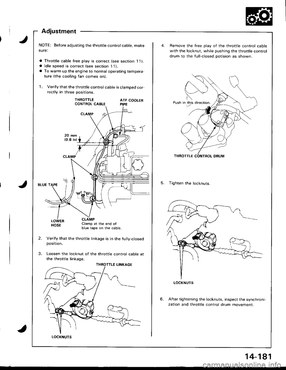
Adjustment
NOTE: Before adjusting the throttle controlcable, make
sure:
a Throttle cable lree play is correct (see section 11).a ldle speed is correct (see section 11).a To warm up the engine to normal operating tempera-
ture {the cooling fan comes on)
1 . Verify that the throttle control cable is clamped correctly in three positions.
THROTTLEATF COOLERPIPE
LOWERHOSEClamp at the end ofblue tape on the cable.
Verily that the throttle linkage is in the fully-closedposttron.
Loosen the locknut of the throttle control cable at
the throttle linkage.
CONTROL CABLE
LOCKNUTS
14-181
Push in this directron.
Remove the free play of the throttle control cable
with the locknut, while pushing the throttle control
drum to the tull-closed potision as shown.
5. Tighten the locknuts.
6.After tightening the locknuts, inspect the synchroni-
zation and throttle control drum movement.
Page 602 of 1681

Differential (81881 engine)
Backlash Inspection
Place differential assembly on V-blocks and install
both axles.
N4easure the backlash ot both pinion gears
Standa.d (Newl: O.O5-0.15 mm (O.OO2-0.006 in)
3. It the backlash is not within the standard, replace
the differential carrier.
Final Driven Gear RePlacement
1. Remove the bolts in a crisscross pattern ln several
steps, then remove the linal driven gear trom the
differential carrier.
NOTE: The final driven gear bolts have left-hand
tnreaos.
10 x 1.0 mm101 N'm 110.3 kgf'm, 74.5 lbf'fll
Left-hand threads
FINAL DRIVEN GEAR
OIFFERENTIALCARRIER
Install the final driven gear by tightening the bolts
in a crissc.oss pattern in several steps.
OIAL INDICATOR
Charnfer on inside diameter ottinal driven gear faces carrier.
\
15-4
Page 610 of 1681
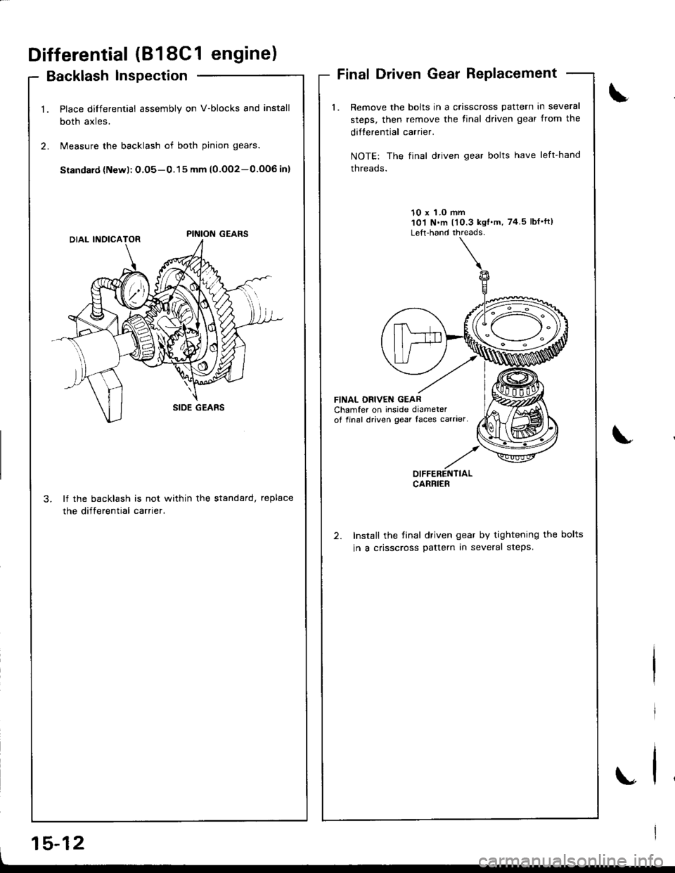
Differential (818C1 engine)
Backlash lnspection
Place differential assembly on V-blocks and install
both axles,
Measure the backlash of both pinion gears.
Siandard {Newl: O.O5-0.15 mm (0.OO2-0.OOG in}
lf the backlash is not within the standard, replace
the differential carrier.
Final Driven Gear Replacement
Remove the bolts in a crisscross pattern in several
steps, then remove the tinal driven gear from the
difterential carrier.
NOTE: The final driven gear bolts have left-hand
threads.
10 x 'l.O mm101 N.m l'10.3 kgt'm, 74 5lbf'ft)
Left-hand threads-
FINAL DBIVEN GEARChamfer on inside diameterof final driven gear Iaces carrier
Install the final driven gear by tightening the bolts
in a crisscross pattern in several steps.
\
.,
OIFFERENTIALCARRIER
I
15-12
Page 619 of 1681
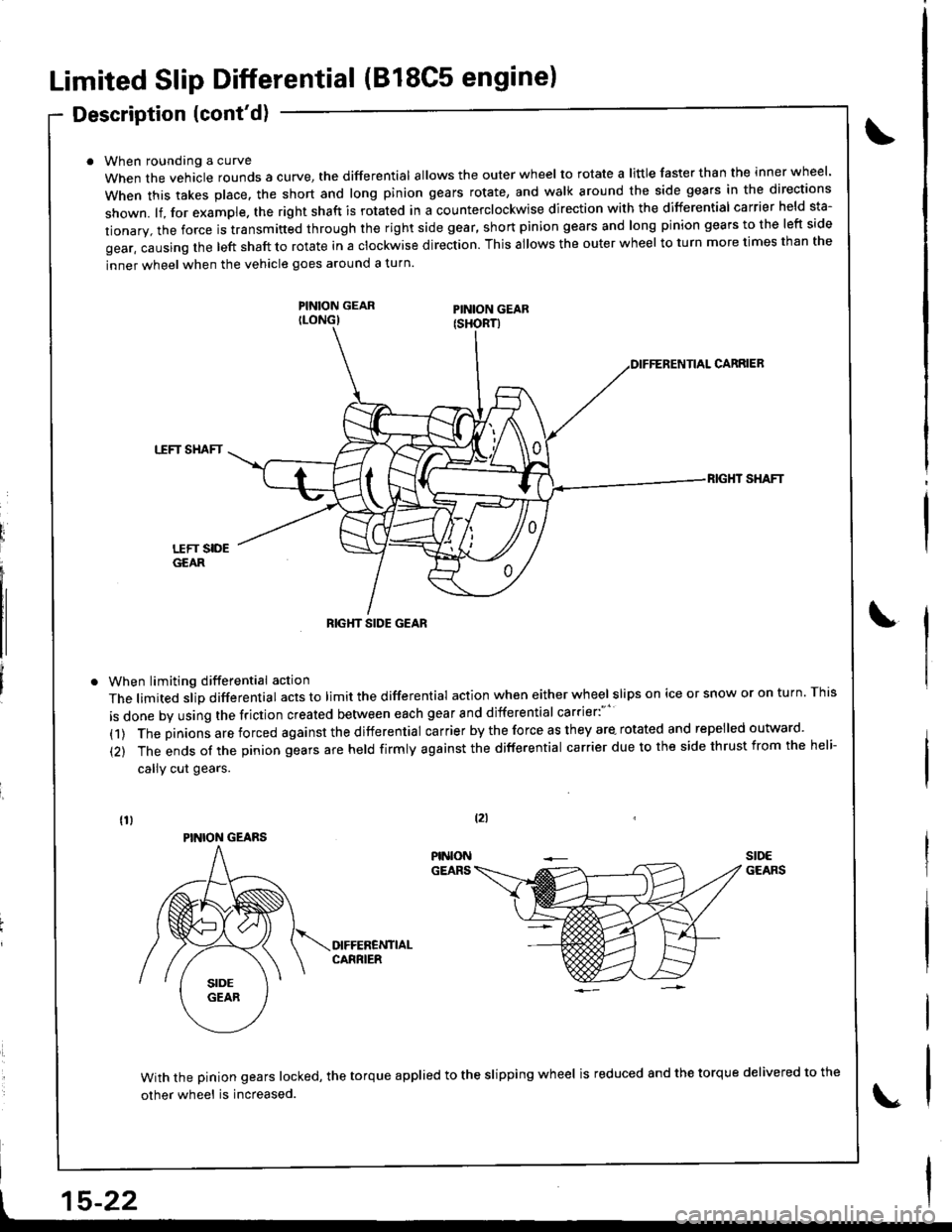
Limited Slip Differential (B18C5 engine)
Description (cont'd)
When roundang a curve
When the vehacle rounds a curye, tne differential allows the outer wheel to rotate a little faster than the inner wheel.
when this takes p|ace. the short and |ong pinion gears rotate, and wa|k around the side gears in the directions
shown. lf, for example. the right shaft is rotated in a counterclockwise direction with the differential carrier held sta-
tionary, the force is transmitted through the right side gear, short pinion gears and long pinion gears to the left side
gear, causing the left shaft to rotate in a clockwise direction. This allows the outer wheel to turn more times than the
inner wheel when the vehicle goes around a turn.
PINION GEARILONG)
When limiting differential action
The limited slip differential acts to limit the differential action when either wheel slips on ice or snow or on turn. This
is done by using the friction created between each gear and differential carrier:"''
(1) The pinions are forced against the differential carrier by the force as they are- rotated and repelled outward.
(2) The ends of the pinion gears are held firmly against the differential carrier due to the side thrust from the heli-
callY cut gears.
CARRIEB
TTFT SHAFT
RIG}IT SHAFT
With the pinion gears locked, the torque applied to the slipping wheel is reduced 8nd the torque delivered to the
other wheel is increased.
tzl
t15-22
RIGHT SIDE GEAR
PINION GEARS
Page 620 of 1681
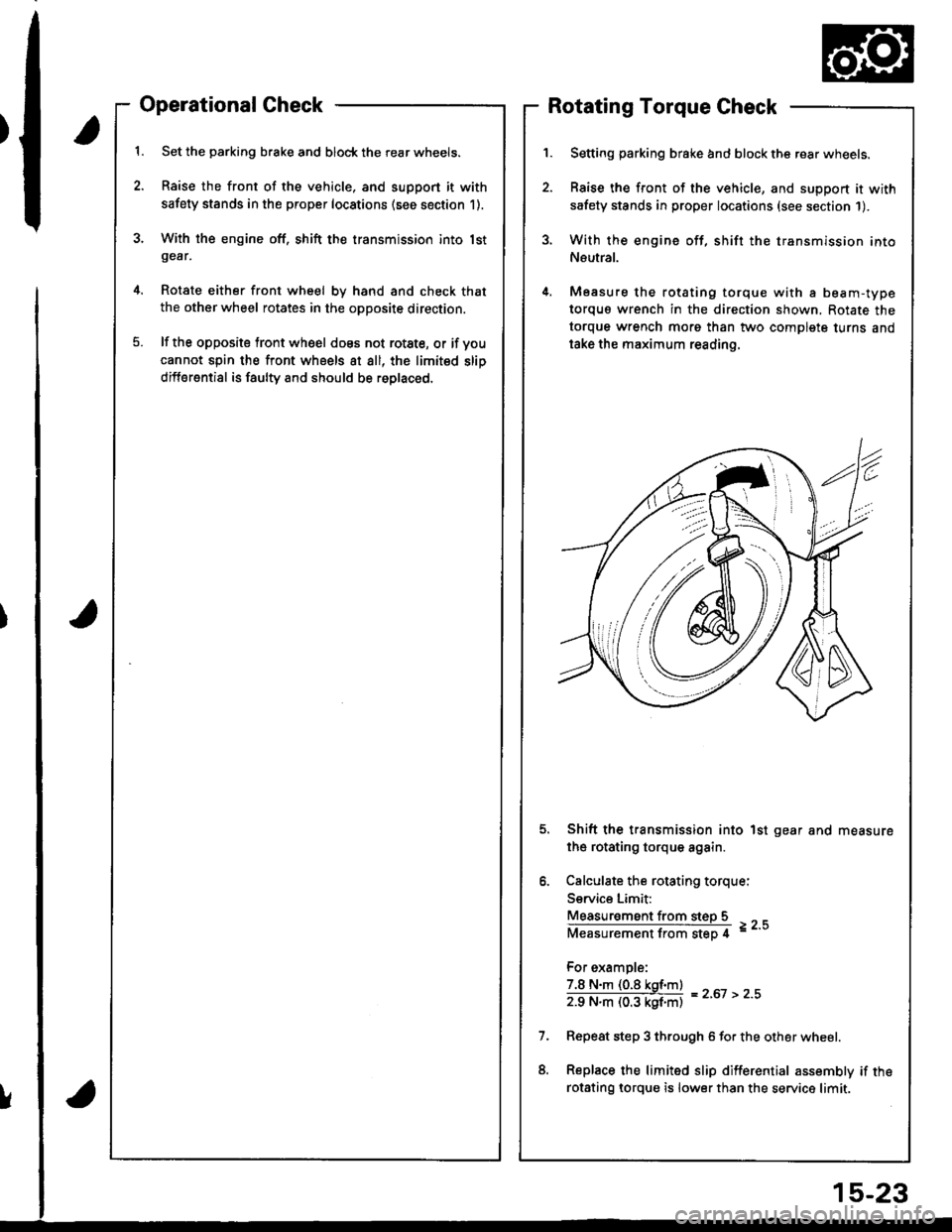
Operational Check
Set the parking brake and block the rear wheels.
Raise the front of the vehicle, and support it with
safety stands in the proper locations (see section 1).
With the engine off, shift the transmission into lstgear,
Rotate either front wheel bv hand and check that
the other wheel rotates in the opposite direction.
lf the opposite tront wheel does not rotste, or if voucannot spin the front wheels at all, the limited slip
differential is faulty and should be roplaced.
Rotating Torque Check
Setting parking brake and block the rear wheels.
Raise the front of the vehicle, and support it with
safety stands in proper locations (see section 1).
With the engine off, shift the transmission into
Neutral.
Measure the rotating torque with a beam-type
torquo wrench in the direction shown, Rotate the
torque wrench morg than two complete turns and
take the maximum reading.
Shift the transmission into 1st gear and measure
the rotating torque again.
Calculate the rotating torque:
Service Limit:
Measur€ment from steD 5
Measurementfrom step 4 =--
For example:
7.8 N.m (0.8 kgf.m)
zg N"ll (03 kgf'ntl = z'ot > z''
Repeat step 3 through 6 for the other wheel.
Replace the limited slip differential assembly if the
rotsting lorque is lower than the service limit.
!
15-23
Page 627 of 1681
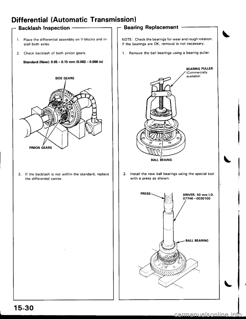
Differential (Automatic Transmissionl
Backlash Inspection
1. Place the dilferential assembly on V-blocks and in-
stall both axles.
2. Check backlash of both pinion gears.
Standard lNsw): 0.05 - 0.15 mm {0.(Xt2 - o.(Xl6 in)
3. lf the backlash is not within the standard, reDlace
the differential carrier.
15-30I
Bearing Replacement
NOTE: Check the bearings for wear and rough rotation
lf the bearings are OK, removal is not necessary.
1. Remove the ball bearings using a bearing puller'
Install the new ball bearings using the special tool
with a press as shown.
SIDE GEARS
EEABING PULLER(CommerciallY
available)
\
DRIVER, 40 mm l.O.07746-0030100
Page 634 of 1681
t
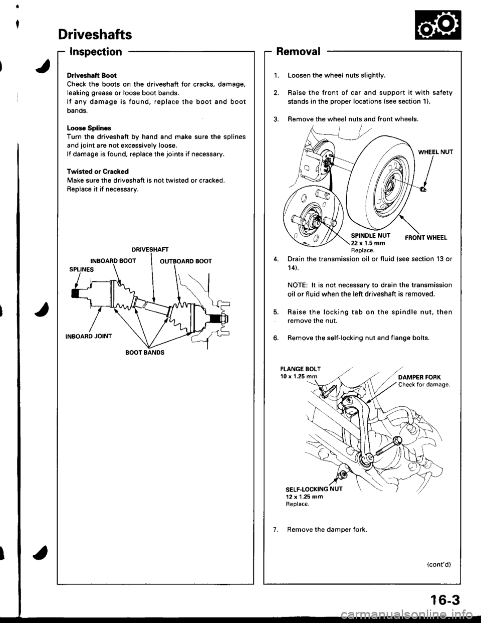
Driveshafts
Inspection
Drivcshatt Boot
Check the boots on the driveshaft tor cracks. damage,
leaking grease or loose boot bands.
lf any damage is found, replace the boot and boot
oanos.
Looso SplineE
Turn the driveshaft by hand and moke sure the splines
and joint are not excessively loose.
lf damage is found, replace the joints if necessary.
Twisled or Crscked
Make sure the driveshaft is not tlvisted or cracked.
Replace it if necessary.
BOOT BANDS
1.Loosen the wheel nuts slightly,
Raise the front of ca. and support it with safety
stands in the prope. locations {see section 1).
Remove the wheel nuts and front wheels.
5.
Drain the transmission oil or fluid (see section 13 or
14t.
NOTE: lt is not necessary to drain the transmission
oil or fluid when the left driveshaft is removed.
Raise the locking tab on the spindle nut, then
remove the nut.
6. Remove the self-locking nut and flange bolts.
FLANGE BOLT'10 x 1.25
SELF.LOCKING NUT
12 x 1.25 mmReplace.
(cont'd)
Replace.
7. Remove the damoer fork.
Removal
6-3
Page 645 of 1681
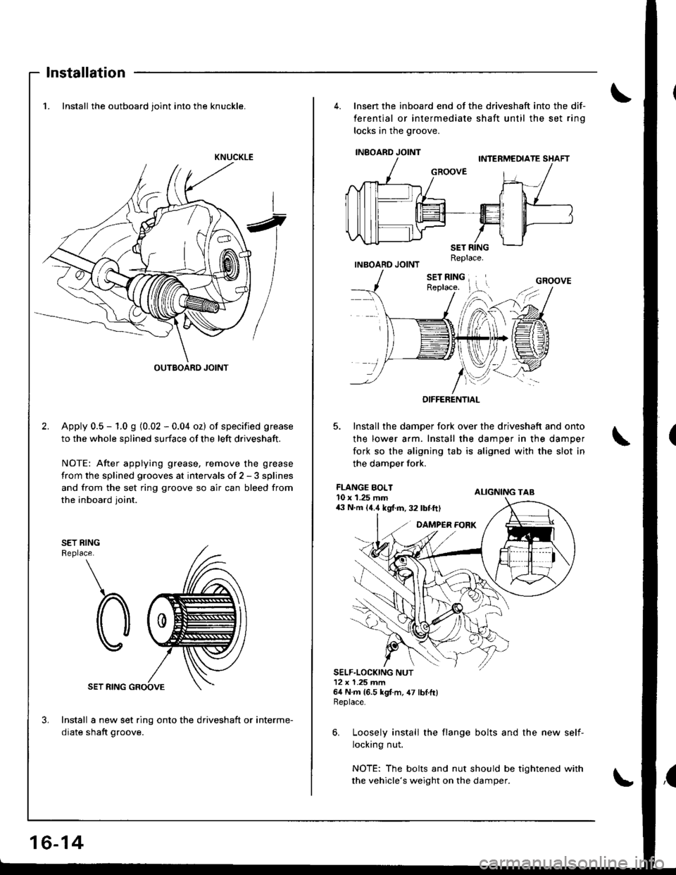
Installation
1. Install the outboard joint into the knuckle.
Apply 0.5 - 1.0 g {0.02 - 0.04 oz) of specified grease
to the whole splined surface of the left driveshaft.
NOTE: After applying grease, remove the grease
from the splined grooves at intervals of 2 - 3 splines
and from the set ring groove so air can bleed from
the inboard ioint.
SET RINGReplace.
SET RING
Install a new set ring onto the driveshaft or interme-
diate shaft groove.
KNUCKLE
OUTBOARD JOINT
16-14
4. lnsen the inboard end of the driveshaft into the dif-
ferential or intermediate shaft until the set rino
locks in the groove.
INEOARD JOINT
INBOARD JOINTReplace.
lnstall the damoer fork over the driveshaft and onto
the lower arm. Install the damper in the damper
fork so the aligning tab is aligned with the slot in
the damoer fork.
ALIGNING TAB
6. Loosely install the flange bolts and the new self-
locking nut.
NOTE: The bolts and nut should be tightened with
the vehicle's weight on the damper.
GROOVE
OIFFERENTIAL
FLANGE BOLT10 x 1.25 mm43 N.m {4.4 kgf.m,32lbtftl
Page 646 of 1681
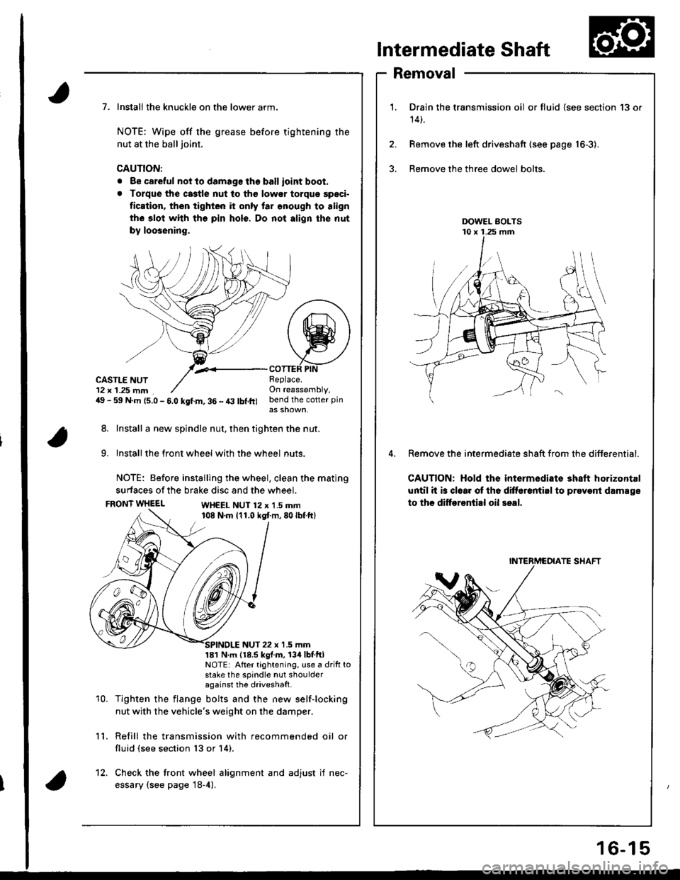
Intermediate Shaft
Removal
Drain the transmission oil or fluid {see section 13 or
14t.
Remove the left driveshaft (see page 16-3).
Bemove the three dowel bolts.
Remove the intermediate sh8ft from the differential.
CAUTION: Hold the intermediate shaft horizontal
until it is clear ot th6 difforantirl to prevont damage
to thc ditf€rential oil seal.
7. Install the knuckle on the lower arm.
NOTE: Wipe off the grease before tightening the
nut at the ball joint.
CAUTION:
. Be careful not to damago the ballioint boot.
. Torque the castle nut to tho low€r torque speci-
tication, then tighten it only lar onough to align
th6 slot whh tho pin hols. Do not align the nut
by loosening.
,.<__coTTEF PtNCASTLE NUT12 x 1.25 mm49 - 59 N.m {5.0 - 5.0 kgf.m, 36 - t3 lbl.ft)
Beplace.On reassembly,bend the cotter pin
8. Install a new spindle nut, then tighten the nut.
9. Installthe front wheel with the wheel nuts.
NOTE: Before installing the wheel, clean the mating
surfaces of the brake disc and the wheel.
FRONT WHEELWH€EL NUT 12 x 1.5 mm108 N.m (11.0 kgt m,80lbf ft)
10.
NUT 22 x '1.5 mm181 N m 118.5 kgl.m, 134lbtftlNOTE: After tightening, use a drift tostake the spindle nut shoulderagainst the driveshatt.
Tighten the flange bolts and the new self-locking
nut with the vehicle's weight on the damper.
Refill the transmission with recommended oil or
fluid (see section 13 or 14).
11.
12. Check the front wheel alignment and adjust if nec-
essary (see page 18-4).
INTERMCOIATE SHAFT
16-15
Page 651 of 1681
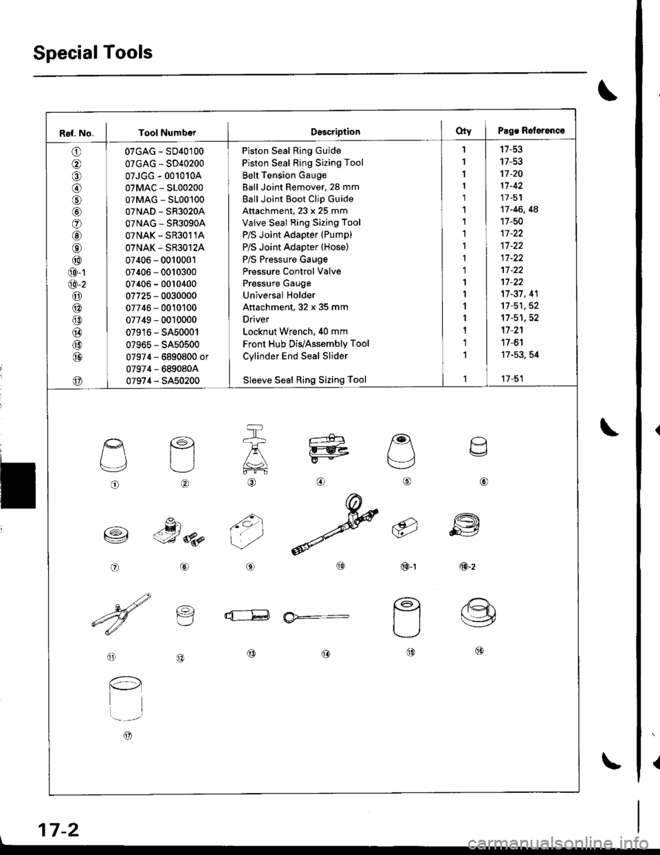
SpecialTools
{
\
\
17-2
Ref. No. I Tool NumberDsscriptionOty I Pags Reterenc.
o
@
@
o
@
@
@
@
@
@-1
@-2
o6:^
@
@
@
@
@
07GAG - SD40100
07GAG - SD40200
07JGG - 001010A
07MAC - S100200
07MAG - S100100
07NAD - SR3020A
OTNAG _ SR3OgOA
OTNAK - SR3O11A
OTNAK - SR3O12A
07406 - 0010001
07406 - 0010300
07406 - 0010400
07725 - 0030000
07746 - 0010100
07749 - 0010000
07916 - SA50001
07965 - SA50500
07974 - 6890800 or
07974 - 6890804
07974 - SA50200
Piston Seal Ring Guide
Piston Seal Ring Sizing Tool
Belt Tension Gauge
Ball Joint Remover, 28 mm
Ball Joint Boot Clip Guide
Attachment, 23 x 25 mm
Valve Seal Ring Sizing Tool
P/S Joint Adapter (Pump)
P/S Joint Adapter (Hose)
P/S Pressure Gauge
Pressure Control Valve
Pressure Gauge
Universal Holder
Attachment, 32 x 35 mm
Driver
Locknut Wrench. 40 mm
Front Hub Dis/Assembly Tool
Cylinder End Seal Slider
Sleeve Seal Ring Sizing Tool
'I
1
1
1
1'|
1,l
I
1
1
1'I
'l
1
1
1
1
1
't7-53
17-53't]-20
11-42
17 -51
17 -46, 4A
17-50
17-37, 41
11-51,52't1-51,52
17 -2'�1
17 -6'l
17-53. 54
17-51
o
L'4,
o
€)
-g)c-J 8p
@
@
6i
(9')\E/'
@-t
a
6
ffi
@-z
d--E ia*=-
o
l-l
t..-_-.r
A)
@@@
\