heater HONDA INTEGRA 1998 4.G Workshop Manual
[x] Cancel search | Manufacturer: HONDA, Model Year: 1998, Model line: INTEGRA, Model: HONDA INTEGRA 1998 4.GPages: 1681, PDF Size: 54.22 MB
Page 50 of 1681
Engine Removal/lnstallation
(cont'd)
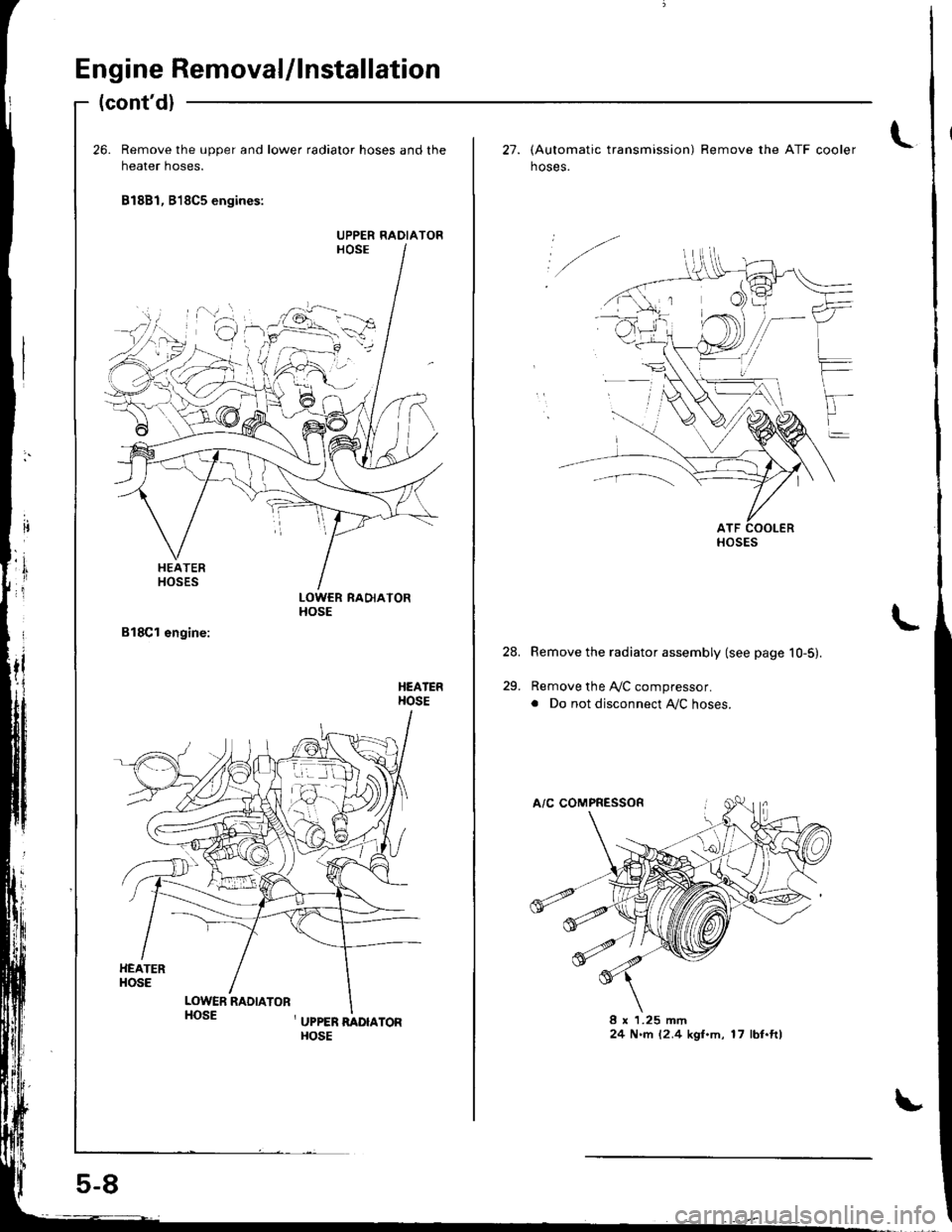
26. Remove the upper and lower radiator hoses and the
heater hoses.
81881, B18C5 engines:
LOWCR RADIATORHOSE
HEATERHOSE
HEATERHOSE
LOWER RADIATORHOSE, UPPER RADIAToRHOSE
UPPER RADIATOR
,1
ir
..f.
c
5-8
t27. lAutomatic transmission) Remove the ATF cooler
hoses.
Remove the radiator assembly (see page 10-5).
Remove the A,/C compressor.
. Do not disconnect Ay'C hoses.
8 x 1.25 mm24 N.rn 12.4 kgl.m, 17 lbf.ft)
24.
29.
HOSES
Page 58 of 1681
Engine Removal/lnstallation
{cont'dl
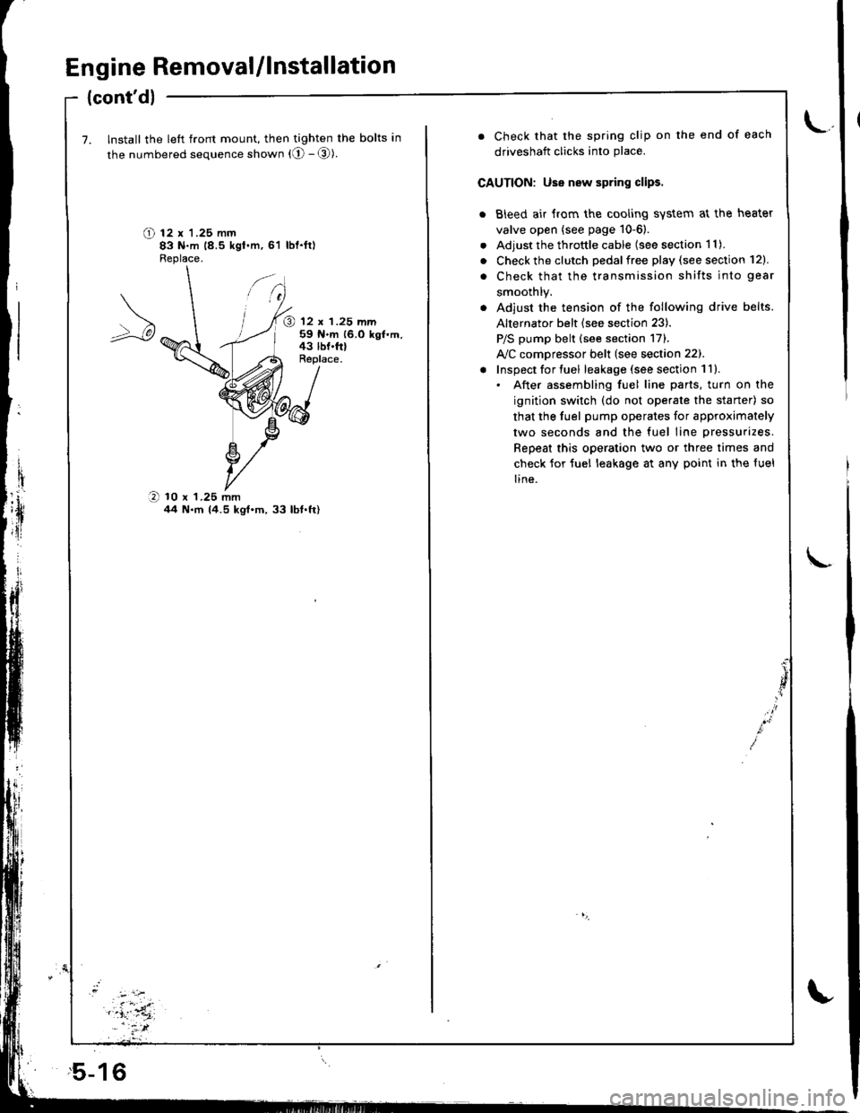
7. Install the left front mount, then tighten the bolts in
the numbered sequence shown (O - @).
O t2 x '1.25 mm83 N.m 18.5 kgt.m,61 lbl.ft)Fleplace.
@ 12 x 1.25 mm59 N.m 16.0 kgf.m,43 lbf.frlReplace.
O 10 x 1.25 mmil4 N.m 14.5 kgt'm,33 lbt.ft)
,5-16
. Check that the spring clip on the end of each
driveshaft clicks into place.
CAUTION: Use new spring clips.
. Bleed air {rom the cooling system at the heater
valve open (see page 10-6).
. Adjust the throttle cable (see section 1 1).
. Check the clutch pedalfree play (see section 12).
. Check that the transmission shifts into gear
smoothlY.
. Adjust the tension of the following drive belts.
Alternator belt {see section 23).
P/S pump belt (see section 171.
A/C comDressor belt (see section 22).
! Inspect for tuel leakage (see section 1ll.. After assembling fuel line parts, turn on the
ignition switch (do not operate the staner) so
that the fuel pump operates for approximately
two seconds and the fuel line pressurizes.
Repeat this operation two or three times and
check for tuel leakage at any point in the {uel
line.
Page 188 of 1681
.'.,.'.attj
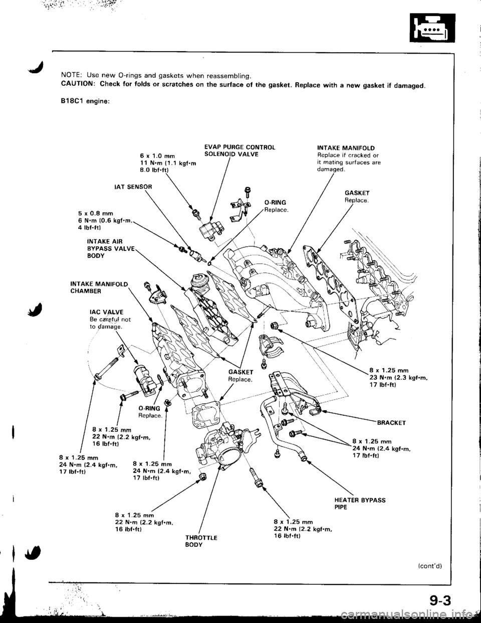
NOTEr Use new O-rings and gaskets when reassembling.CAUTION: Check for folds or scratches on the surlace ot the gasket. Replace with a new gasket if damaged.
818C1 engine:
6 x 1.0 mm11 N.m {1.1 kgt.m8.O tbt.trl
EVAP PURGE CONTROLSOLENOID VALVEINTAKE MANIFOLDReplace if cracked orit mating surfaces are
rAc v4f,vE8e caie{ul notto
IAT SENSOR
8 x 1.25 mm24 N.m 12.4 kgt.m,17 tbf'fr)
22 N.m 12.2 k'l.m,16 lbf.ftl
O-BINGReplace.5x0.8mm6 N.m (0.6 kgI'm,4 tbf.trl
INTAKE AIRBYPASS VALBODY
INTAKE MANIFOLOCHAMBER
8 x 1.25 mm23 N.m 12.3 kgt.m,17 tbf.ft)
8 x 1.25 mm22 N.m 12.2 kgt.m,16 tbt'tr)I x 1.25 mm24 N.m (2.4 kgl.m,17 tbf.ft)8 x 1.25 mm24 N.m (2.4 kgt.m,17 tbf.frl
HEATER BYPASSPIPE
8 x 1.25 mm22 N.m 12.2 kgt.m,16 lbt.fr)THROTTLEEODY
(cont'd)
9-3
Page 196 of 1681
lllustrated Index
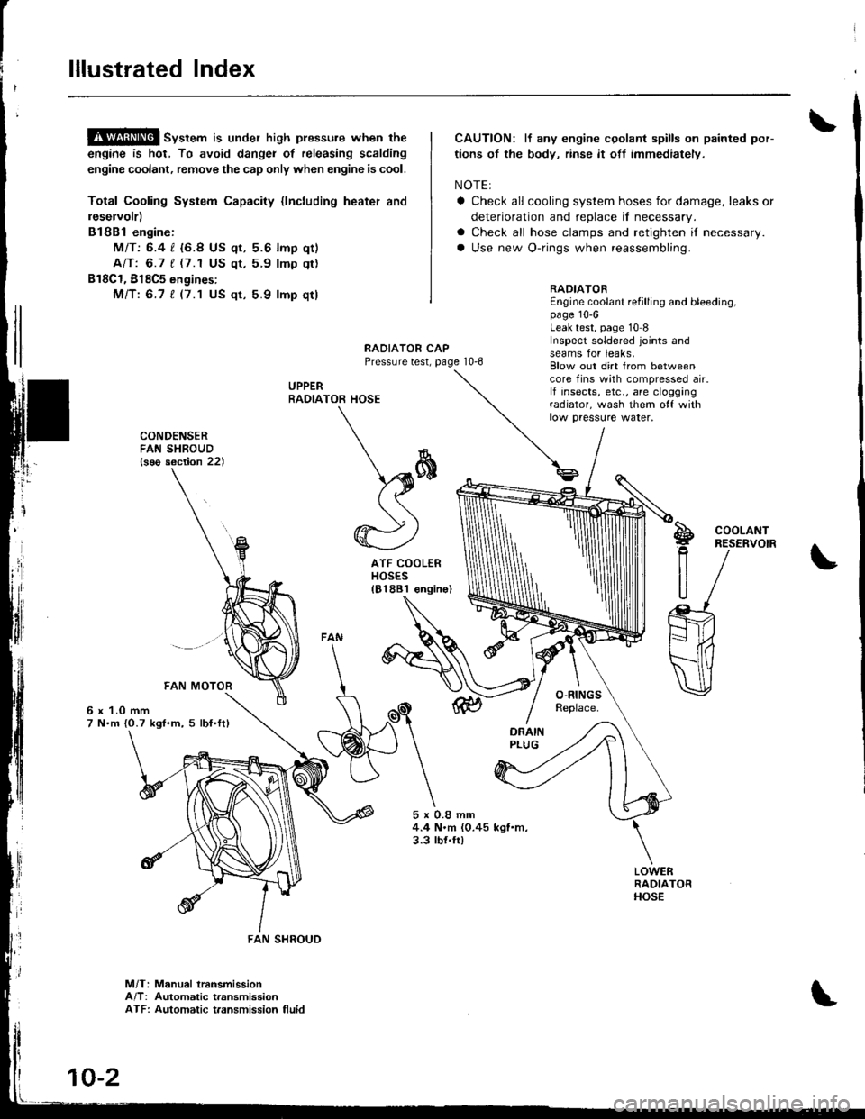
!$!!@ sv"t"m is under high plessure when the
engine is hot, To avoid dangei of releasing scalding
engine coolant, remove the cap only when engine is cool.
Total Cooling System Capacity {lncluding heater and
leservoir)
Bl8Bl engine:
MIT: 6.4 l. {6.8 US qt, 5.6 lmp qt)
Ant 6.7 t (7.1 US qt,5.9 lmp qt)
B18C1, 818C5 engines:
Mfi:6.7 t (7.1 US qt, 5.9 lmp qt)
CAUTION: lf any engine cgolant spills on painted por-
tions of the body, rinse it off immediately.
NOTE:
a Check all cooling system hoses for damage, leaks or
deterioration and replace il necessary.
a Check all hose clamps and retighten if necessary.
a Use new O-rings when reassembling.
RADIATOREngine coolant refilling and bleeding,page 10-6Leak test, page 10 8Inspecl soldered joints andseams for leaks,RAOIATOR CAPPressure test, page 10-8
UPPERRADIA
rl
]
CONDENSERFAN SHROUD{s€o section 22)
6 x 1.0 mm7 N.m {0.7 kgl.m, 5 lbf'ftl
5x0.8mm4.4 N.m (0.45 kgl.m,3.3 tbt.ft)
Blow out dirt from betweencore fins with compressed air.lf insects, etc., are cloggingradiator, wash them o{f withlow paessure water,
TOR HOSE
\*
\sffi((
@)
ATF COOLERHOSES181881 €ngin
S!g
R
U
COOLANTRESERVOIR
M/T: Manual lransmissionA/T: Automatic transmissionATF: Automatic t.ansmission fluid
FAN SHROUD
10-2
Page 197 of 1681
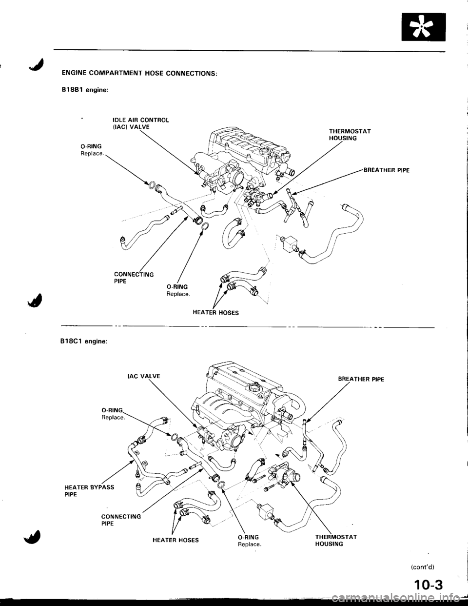
ENGINE COMPARTMENT HOSE CONNECTIONS:
B18B1 engine:
IDLE AIR CONTROL(IAC) VALVE
O-RINGReplace.
BREATHER PIPE
---___...----rs
W
l/TER HOSES
Bl8Cl engine:
HEATER BYPASSPIPE
THER PIPE
AT
(cont'd)
)
HEATER HOSES
10-3
Page 198 of 1681
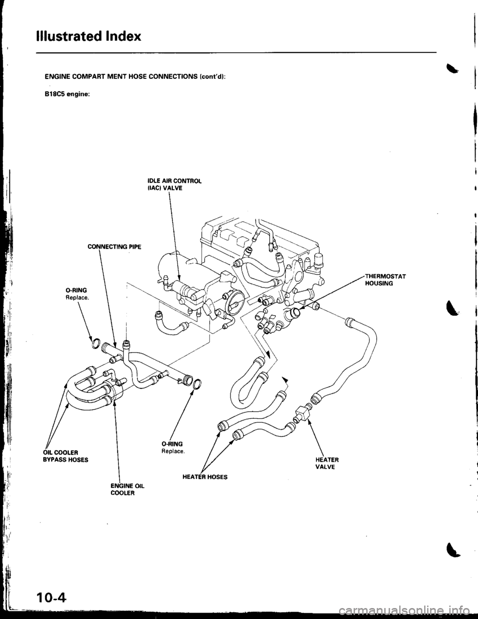
lllustrated Index
\ENGINE COMPART MENT HOSE CONNECTIONS lconi'dl:
818C5 engine:
IDLE AIR CONTROLIIAC} VALVE
THERMOSTATHOUSING
\
\
O.RINGReplace.
\@
/
O-RINGFeplace.OIL COOLERBYPASS HOSESHEATERvAt_vE
COOLER
Page 200 of 1681
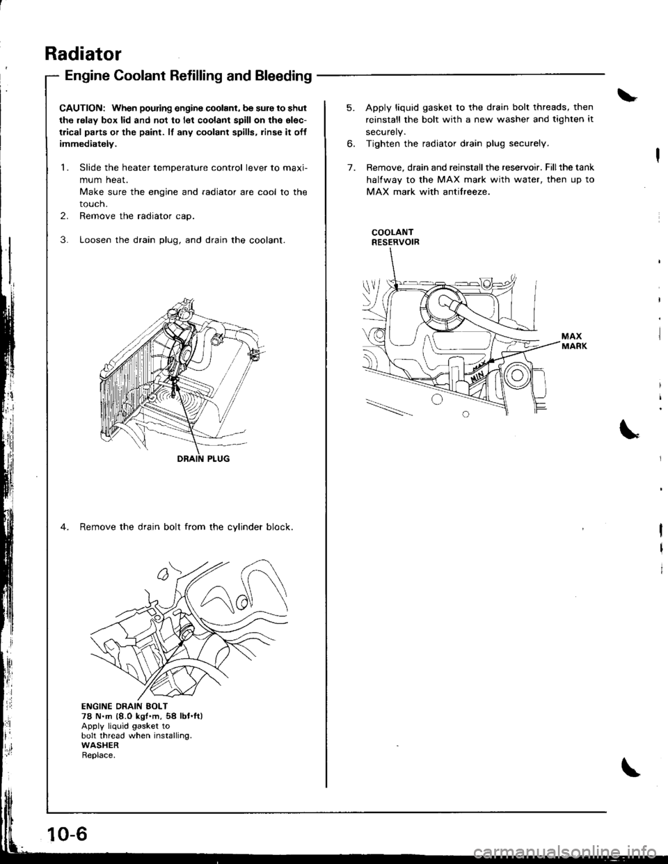
Radiator
Engine Coolant Refilling and Bleeding
CAUTION: When pouring engine coolant, be sure to shut
th6 relay box lid and not to l€t coolant spill on th6 el€c-
trical parts or the paint. lf any coolant spills, rinse it off
immediately.
1. Slide the heater temDerature control lever to maxi-
mum heat.
Make sure the engine and radiator are cool to the
touch.
2. Remove the radiator cap.
3. Loosen the drain plug, and drain the coolant.
4. Remove the drain bolt from the cvlinder block.
ji
Ii'
l:ll
ENGINE DRAIN EOLT78 N.m {8.0 kgt'm,54 lbt.ft)Apply liquid gasket tobolt thread when installing.WASHERReplace.
10-6
5. Apply liquid gasket to the drain bolt threads, then
reinstall the bolt with a new washer and tighten it
securely.
6. Tighten the radiator drain plug securely.
7. Remove, drain and reinstall the reservoir. Fillthe tank
halfway to the MAX mark with water, then up to
MAX mark with antifreeze.
COOLANTRESERVOIR
I
I
I
Page 206 of 1681
i
iFuel and Emissions
SDeciaf Toofs ..,...,...............11-2
Component Locations
Index.,..,.,..................................,.,.,.,.,.,..,.,....... 11-3
System Description
Vacuum Connections ..................................,. 11-8
Electrical Connections ................................... 1 1-14
System Connectors ....,.,.,.,............................ 1 1-22
Troubleshooting
Troubfeshooting Procedures ........................ 11.32
Engine Control Module T€rminalArrangement .,.,.,..,.,. 11-39
Diagnostic Trouble Cods Chart .......-.-.......... 11-42
Howto Read Flowcharts ......,..,.,................... 1147
PGM-Fl System
System Description ............ 11-4
Troubleshooting Flowcharts
Engine Control Module ............,...,..,.,........... 11-50
Manifold Absolute PressureSensor...............................,..,.,...,................ 11-54
Intake Air TemDerature Sensor ..........,...,..... 11-58
Engine Coolant TemperatureSensor ....................,.,...,.,........................... 11-60
Throttle Position Sensor .,...........................,. 11-63
Primary Heated Oxygen Sensor(Sensor'l) .......,......,.,. 11-67
Secondary Heated Oxygen Sensorlsensor 2) .................. 11-71
Heated Oxygen Sensor Heater .....................'t1.74
Fuel Supply System ....................................... 1 1-76
Random Mistire ............. 11-78
Misfire Detected in One Cylinder .....,..:,,.,.... 11-79
Knock Sensor .........,.,..,. f -A2
Crankshaft Position/Top Dead Center/Cylinder Position Sensor .,........................ 11-83
Vehicle Speed Sensor .............,.,.,.,....,........... 11-85
Barometric Prsssute Sensor ..,...................... 11-86
Electrical Load Detector ...................,.,.......... 11-88
Crankshaft SDeed FluctuationSensor ...........................................,...,........ 11-90
ECM lnternal Circuit,..............................-......, 11-92
A/T Fl Date Line ............ 11-93
A/T Fl Signal A/B .......... 11-95
I,-1
Page 219 of 1681
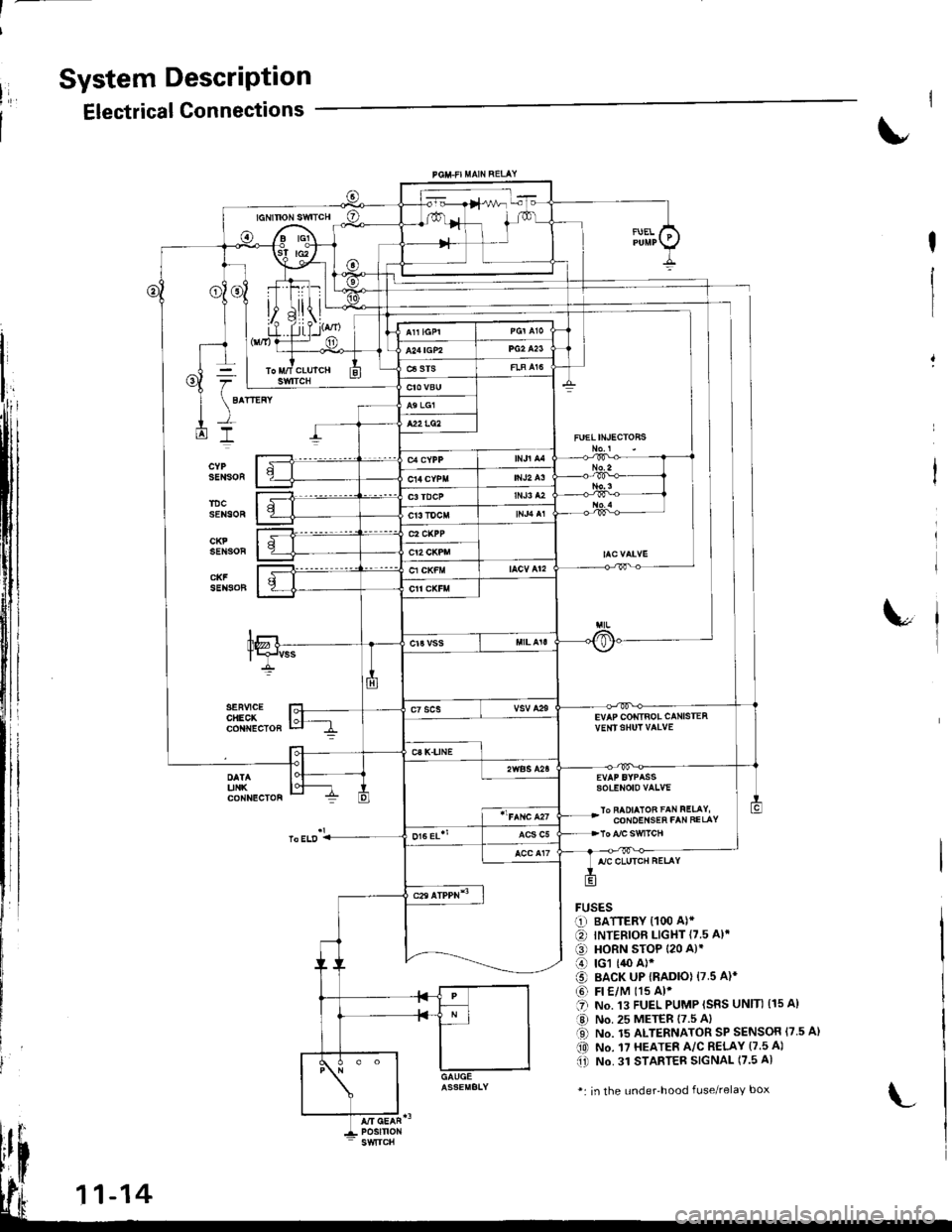
System DescriPtion
Electrical Connections
FUELIN'ECTOHS
EVAP COIiTIBOL CANISTEAvE|rISHUT VAIVE
sotENoto vaLvE
lo FAOIAIOB FAN FELAY,CONOEI{SEh FAN FELAY
FUSESr-1) BATTERY {100 A)*
€) INTERIOF LIGHT {7.5 A}.
€) HORN STOP 120 A)'
o rcl (,$ A)*
o BACK UP IRADIO) 17.5 A)*
@ Fr €/M t15 Al'.'I NO. .I3 FUEL PUMP ISRS UNIN (15 A)
a,J No. 25 METER 17.5 Al
O No. 15 ALTERNATOR SP SENSOR {7.5 A}(0 No. 17 HEATER A/C R€LAY (7.5 A)(i) No. 31 STAnTEB SIGNAL (7.5 A)
*: in the under'hood fuse/relaY box
Page 244 of 1681
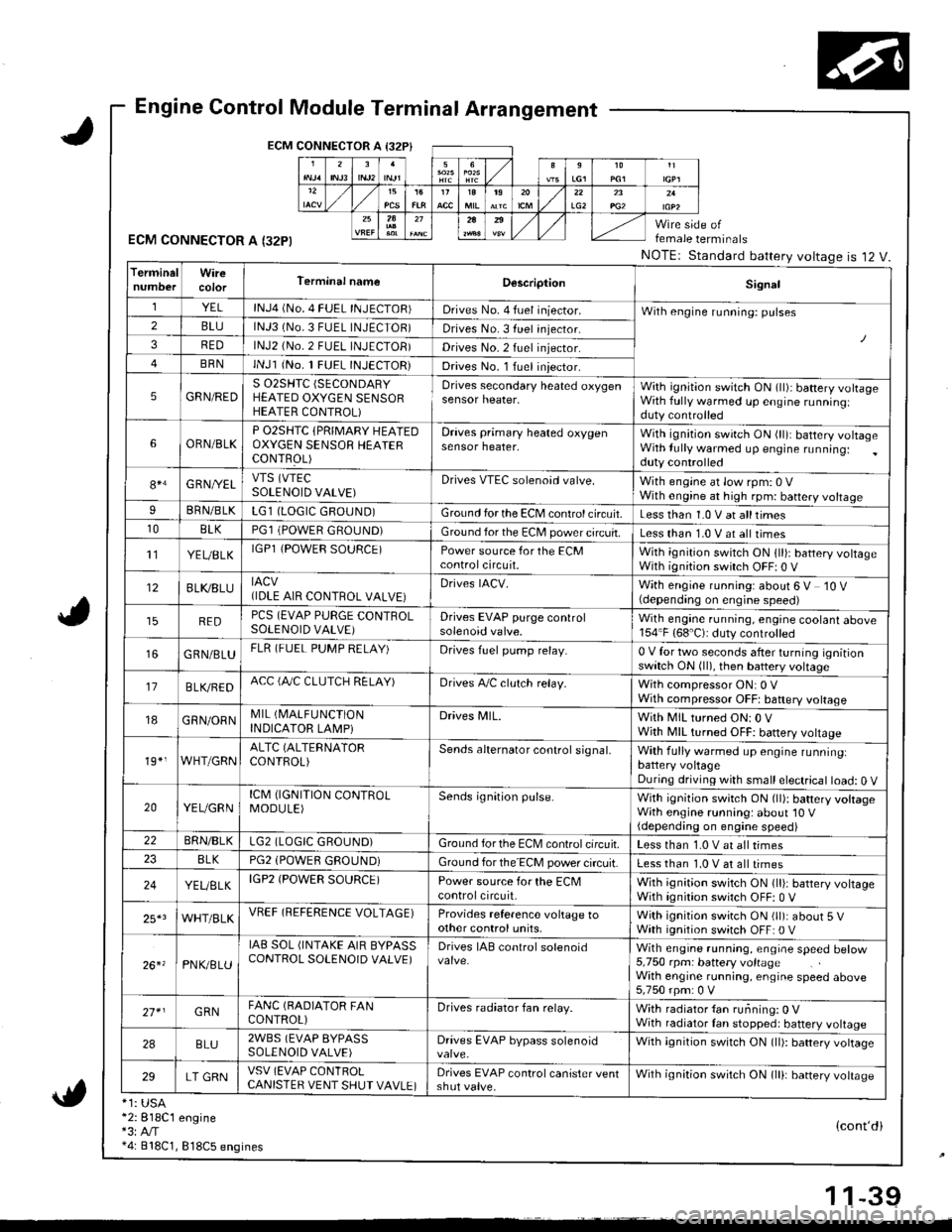
Engine Control Module Terminal Arrangement
ECM CONNECTOR A I32P}
ECM CONNECTOR A I32PI
*1: USA*2:818C1 engine*3:A,/T*4: 818C1, 818C5 engines
female terminals
NOTEr Standard battery voltageis 12 V.
{cont'di
LG22A
TerminalWireTerminal nameDescriptionSignal
YELlNJ4 (No. 4 FUEL INJECTOR)Drives No. 4 fuel iniector.With engine running: pulses2BLUlNJ3 (No.3 FUEL INJECTOR)Drives No. 3 fuel injector.
3REDlNJ2 (No.2 FUEL INJECTOB)Drives No.2 fuel injector.
BRNlNJl (No. 1 FUEL INJECTOR)Drives No. l Iuel iniector.
5GRN/REDS 02SHTC (SECONDARY
HEATED OXYGEN SENSORHEATER CONTROL)
Drives secondary heated oxygensensor heater,With ignition switch ON (ll)i battery volrageWith fully warmed up engine runningiduty controlled
6ORN/BLKP O2SHTC {PRIMARY HEAIEDOXYGEN SENSOB HEAIERCONTFOL)
Draves primary heated oxygensensor heater,With ignition swirch ON (ll): battery voltageWith lully warmed up engine running:duty controlled
84G RNI/ELVTS (VTEC
SOLENOID VALVE)Drives VTEC solenoid valve.With engine at low rpm: 0 VWith engine at high rpm: battery voltageIBRN/BLKLG1 (LOGIC GROUND)Ground for the ECM control circuit.Less than 1.0 V at alltimes10BLKPGl (POWER GROUND)Ground for the EC[, power circuit.Less than 1.0 V at all times't'lYEUBLKIGPl {POWER SOURCE)Power source for the ECMcontrolcircuit.With ignition switch ON 1ll): battery voltageWith ignition switch OFF| 0 V
12BLI(8LUIACV(IDLE AIR CONTROL VALVE}Drives IACV.With engine running: about 6 V 10 V(depending on engine speed)
REDPCS (EVAP PURGE CONTROLSOLENOID VALVE)Drives EVAP purge controlsolenoid valve.Wilh engane running, engine coolant above154"F (68'C): duty controlled
GRN/BLUFLR (FUEL PUMP RELAY)Drives fuel pump relay.0 V for two seconds after turning ignitionswitch ON (ll), then battery voltage
17B LVBEDACC (fuC CLUTCH RELAY)Drives A,/C clulch relay.With compressor ON: 0 VWith compressor OFFt baftery voltage
18GRN/ORNMIL (I\4ALFUNCTION
INDICATOR LAMPiDrives MlL.With MIL turned ON:0 VWjth MIL turned OFF: battery vottage
19*,WHT/GRNALTC (ALTERNATOR
CONTROL)Sends alternator control signal,With fully warmed up engine runninglbattery voltageDuring driving with small electrical load: 0 V
20YEUGRNICM (IGNITION CONTROLMODULE)Sends ignition pulse.With ignition switch ON (ll): battery voltageWith engine running: about'10 V(depending on engine speed)22BRN/BLKLG2 (LOGIC GROUND)Ground forthe ECM controlcifcuit.Less than 1.0 V at all times8LKPG2 (POWEfl GROUND)Ground for the ECM power circuit.Less than 1.0 V at all times
24YEUELKIGP2 (POWER SOURCE)Power source for the ECMcontrolcircuit,With ignition switch ON {lli: battery voltageWith ignition switch OFF: 0 V
25*3WHT/BLKVREF (REFERENCE VOLTAGE)Provides reference voltage toother control units,With ignition swirch ON (ll): about 5 VWath ignition switch OFF: 0 V
26. 'PNK/8LU
IAB SOL (INTAKE AIR BYPASSCONTROL SOLENOID VALVE)Drives IAB conlrol solenoidWith engrne running, engrae speed betow5,750 rpm: battery voltageWith engine running, engine speed above5,750 rpm: 0 V
27* IGRNFANC (BADIATOR FANCONTROL)Drives radiator fan relay.With radiator {an running: 0 VWith radiator Ian stopped: battery voltage
2ABLU2WBS (EVAP BYPASSSOLENOID VALVE)Drives EVAP bypass solenoidWith ignition switch ON (ll): battery vottage
29LT GRNVSV (EVAP CONlROLCANISTER VENT SHUT VAVLE)Drives EVAP control canister ventshut valve.Wilh ignilion switch ON lll): banery votrasc
1 1-39