battery HONDA INTEGRA 1998 4.G User Guide
[x] Cancel search | Manufacturer: HONDA, Model Year: 1998, Model line: INTEGRA, Model: HONDA INTEGRA 1998 4.GPages: 1681, PDF Size: 54.22 MB
Page 305 of 1681
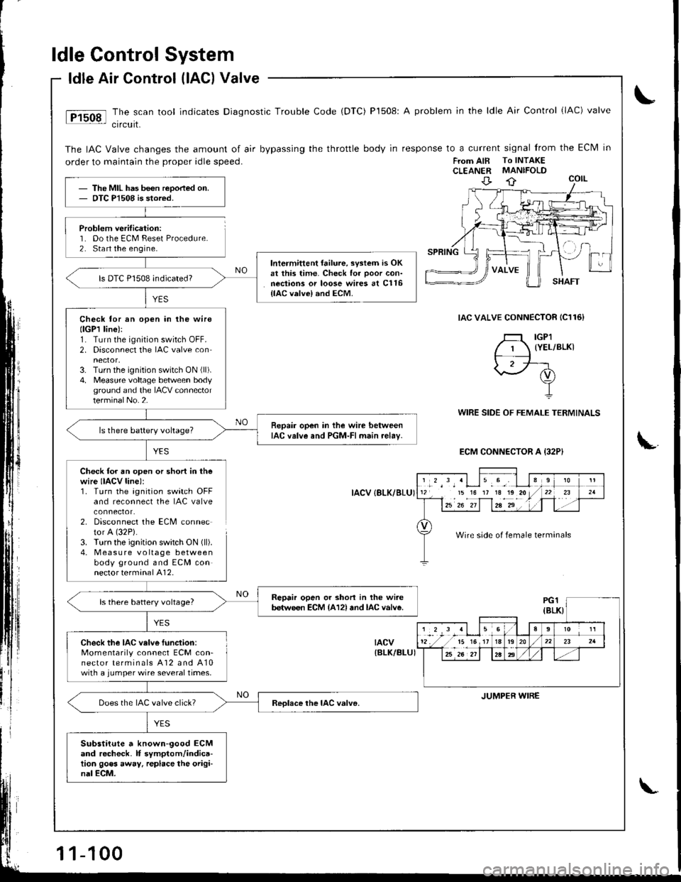
ldle Control System
Problem verification:'1. Do the ECM Feset Procedure.2. Sta rt the engine.
ldle Air Control (lAG) Valve
The scan tool indicates Diagnostic Trouble Code (DTC) P1508: A problem in the ldle Air Control (lAC) valve
crrcurt.
The IAC Valve changes the amount of air bypassing the throttle body in response to a current signal from the Eclvl in
order to maintain the proper idle speed.FTom AIB To INTAKECLEANER MANIFOLD
IAC VALVE CONNECTOR IC116}
YES
WIRE SIDE OF FEMALE TERMINALS
ECM CONNECTOR A {32PI
Check for an open or short in thewire IIACV line):1. Turn the agnition switch OFFand reconnect the IAC valve
2. Disconnect the ECM connector A (32P).
3. Turn the ignition swatch ON (ll).
4. M easu re voltage betweenbody ground and ECM connector terminal A12.
IACV {8LK/BLU}
tacv{BLK/BI-UI
The MIL has been reoorted on.OTC Pl508 is stored.
lntermittent failure, svstem is OKat this time. Check for ooor con-nections or loose wires at C116{lAC valvel and ECM.
ls DTC P1508 indicated?
Check tor an open in lhe wirellGPl line):1. Turn the ignition switch OFF.2. Disconnect the IAC valve con
3. Turn the ignition switch ON (ll).
4. Measure voltage betlveen bodyground and the IACV connectorterminalNo.2.
Repair open in the wire betweenIAC valve and PGM-FI main relav-ls there battery voltage?
Repair open or shon in the wi.ebetween ECM {A12l and lAc valve.ls there battery voltage?
Check the IAC velve function:Momentarily connect ECM con-nector terminals A12 and A10with a jumper wire several times.
Does the IAC valve click?
Substitute a known-good ECMand rocheck. lf symptom/indica-tion goes away. replace the origi-nal ECM.
','*',,'Llu.9', I l112 15 16 17 1a1o20/
l--12u1 z"-if1za-2"' . '1 .
910
t-r '21
Wire side of female terminals
JUMPER WIRE
1-100
Page 306 of 1681
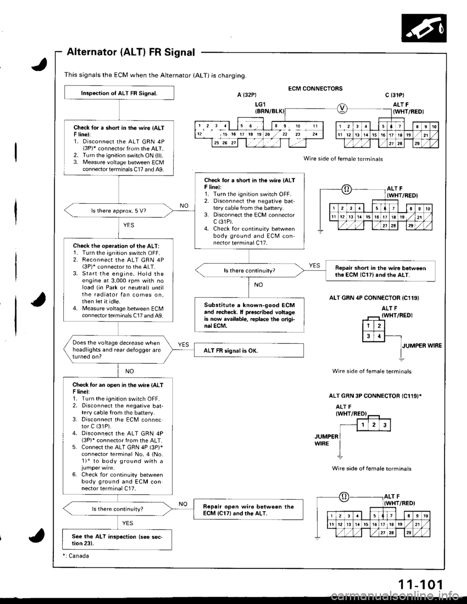
This signals the ECM when the Alternator (ALT) is charging.
Alternator (ALT) FR Signal
Check lor a short in th€ wire {ALTF line):1. Oisconnect the ALT GRN 4P(3P)* connector from the ALT.2. Turn the ignition switch ON {ll).3. Measure voltage between ECMconnector terminals C17 and A9.
ECM CONNECTORSA t32Pt
LG1
c 13lPl
ALT F(WHT/FEDI
Wire side of female terminals
ALT GRN 4P CONN€CTOR {C119}
JUMPER WIRE
Wire side of female terminals
ALT GRN 3P CONNECTOB {C119)*
JUMP€RWIRE
Wire side ot female terminals
12 15 t6 rr t8 19I
?
oALT F(WHT/REOI
23aI10
t112t3t5l6r819 ,/21
./,/,/2a29
[,ALT FIWHT/RED)
12339
11 12l517 tla19 ,/21
Inspection of ALT FR Signal.
Check for a shon in the wire {ALTF line):1. Turn the ignition switch OFF.2. Disconnecl the negative baatery cable from the battery.3. Disconnect the ECM connectorc (31P).
4. Check for continuity betweenbody ground and ECM con-nector terminal C17.
ls there approx.5 V?
Check the operation ofthe ALT:1. Turn the;Onition switch OFF-2. Reconnect the ALT GRN 4P(3P)* connector to the ALT.3. Start the engine. Hold theengine at 3,000 rpm wkh noload {in Park or neutral) untilthe radiator fan comes on,then let it idle.4. Measure voltage bet/veen ECMcon nector termina ls C17 and A9.
Ropair short in the wir6 betweenth6 ECM (C17) and the ALT.
Substitute a known-good ECMand recheck. It prescribed voltagGis now available, replace th€ origi-nal ECM.
Does the voltage decrease whenheadlights and rear defogger areturned on?ALT FR signal is OK.
Check tor an open in the wire {ALTF line):1. Turn the ignition switch OFF-2. Disconnect the negative bat-tery cable from the battery.3. Disconnect the ECM connector C (31P).
4. Disconnect the ALT GRN 4P(3Pi* connector from the ALT.5. Connect the ALT GRN 4P (3p)*
connector terminal No. 4 (No.'l)* to body ground with a
6. Check for continuity betweenbody ground and ECM connector terminal C17.
Ropair open wire bstw€an theECM {C17} and rhe ALT.ls there continuity?
ri Canada
11-101
Page 310 of 1681
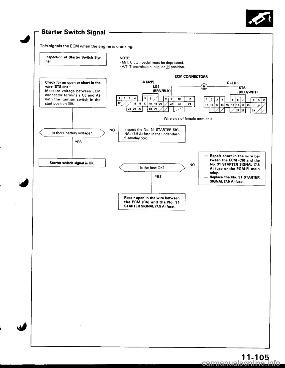
Starter Switch Signal
This signals the ECM when the engine is cranking.
NOTEI. M/T:Clutch pedal must be depressed.. A,/T: Transmission in E or E position.
Wire sida of female terminals
Check for an opon or short in thcwi.. ISTS lin.l:Measure voltage between ECMconnector terminals C6 and Agwith the ignition switch in thostart position (lll).
Inspect the No.31 STARTER SIG-NAL (7.5 Alluse in the under-dashfuse/relay box,
ls there battery voltage?
- Repair 3hort in the wire be-tween tho ECM lc6l rnd theNo. 31 STARTER SIGNAL (7.sAl tus€ or the PGM-FI mainr€lay.- Roplace the No. 31 STARTERSIGNAL 17.5 Al fuso.
Starter switch signal b OK.
Ropair open in tho wire botwaonih6 ECM {CGl and the No, 3lSTARTER SIGNAL {7.5 Al fuse.
11-105
Page 313 of 1681
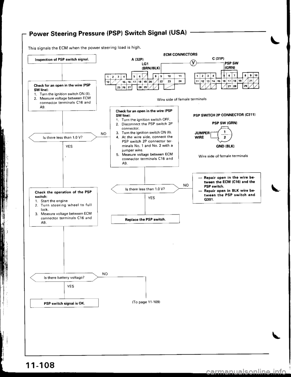
Power Steering Pressure (PSP) Switch Signal (USA)
This signals the ECM when the power steering load is high.
ECM CONNECTORS
Check lor an open in the wire (PSP
SW line):1. Turn the ignition switch ON (ll).
2. Measure voltage between ECM
connector terminals C16 andA9.
A {32P1LGl{BRN/BLK)
c (31P}
PSP SWIGRNI
Wire side oI female termanals
PSP SwlTCH 2P CONNECTOR IC311I
PSP SW {GRNI
luupen r-{ r \wrRE 4rl
GND (BLK)
Wire side oI female terminalsi,
Inspection ot PSP switch signal.
Check lor an op€n in the wire (PSP
SW linel:1. Turn the ignition switch OFF
2. Disconnect the PSP swirch 2P
3. Turn the ignition switch ON (ll).
4. At the wire side, connect the
PSP switch 2P connector ter
minals No. 1 and No.2 with a
iumper wire.5. Measure voltage teNveen ECM
connector terminals C16 andA9.
ls there less than 1.0 V?
- Repair open in the wire be-
tween the ECM lcl6l .nd the
PSP 3witch.- Repai. open in BLK wire be'
tween the PSP switch and
G301.
ls there less than 1.0 V7Check the operation of the PSPswitch:1- Stan the engine2. Turn steering wheel to full
3. Measure voltage between ECM
connector terminals c16 andA9.
ls there battery voltage?
PSP switch signal is oK.{To page l1 t09)
Page 314 of 1681
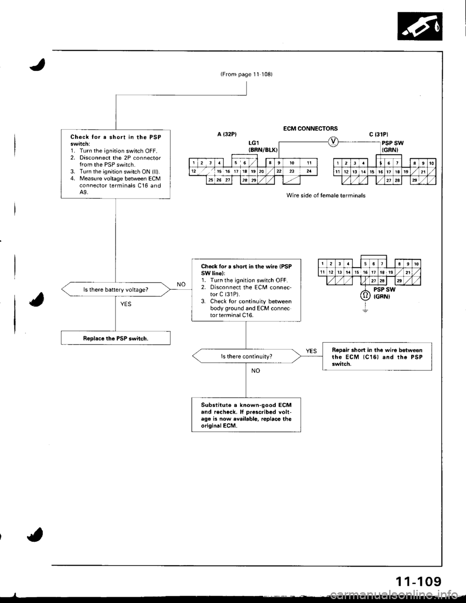
(From page 11 108)
Check tor e short in the PSPswitch:1. Turn the ignition switch OFF.2. Disconnect the 2P connectorfrom the PSP switch.3. Turn the ignition switch ON (ll).4. Measure voltage between ECMconnector terminals C16 andA9.
Ch€ck for a short in the wire {PSPSW lihell1. Turn the ignition switch OFF.2. Disconnect the ECM connec-tor C (31P).
3. Check tor continuity betweenbody ground and ECM connectorterminalCl6.
ls there battery voltage?
ReDair short in the wire betweenthe ECM lC16) and lhe PSPswitch.
Substituto a known-good ECMand recheck. lf prescribed volt-a96 is now available, replace theoriginalECM.
A {32P)ECM CONNECTORS
Wire side of temale terminals
c 13lPl
LG1{BRN/BLK)PSP SWIGRNI
1 1-109
Page 320 of 1681
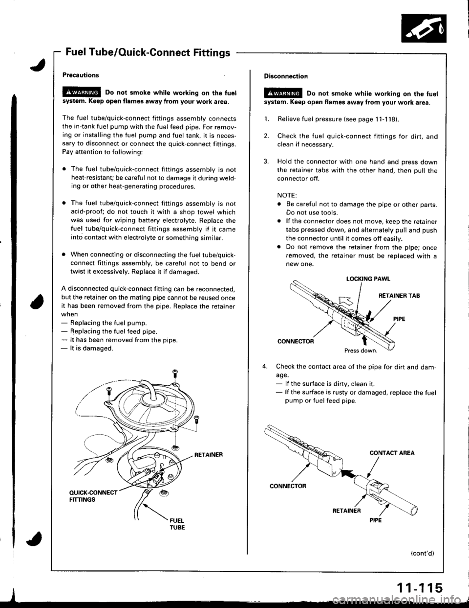
Fuel Tube/Ouick-Connect Fittings
Prgcautions
!@@ Do not smoke while working on the fuel
sysiem. K€ep open flames away from your work area.
The fuel tube/quick-connect fittings assembly connectsthe in-tank tuel pump with the fuelfeed pipe. For remov-
ing or installing the fuel pump and fuel rank, it is neces,sary to disconnect or connect the quick-connect fittings.
Pay attention to following:
r The fuel tube/quick-connect fittings assembly is not
heat-resistanU be careful not to damage it during weld-ing or other heat-generating procedures.
. The fuel tube/quick-connect fittings assembly is not
acid-proof; do not touch it with a shop towel which
was used for wiping battery electrolyte. Replace the
fuel tube/quick-connect fittings assembly if it came
into contact with electrolyte or something similar.
. When connecting or disconnecting the fuel tube/quick-
connect fittings assembly, be careful not to bend or
twist it excessively. Replace it if damaged.
A disconnected quick-connect fitting can be reconnected,
but the retainer on the matlng pipe cannot be reused once
it has been removed from the pipe. Replace the retainer
when- Replacing the fuel pump.- Replacing the fuel feed pipe.- It has been removed trom the oiDe.- lt is damaged.
RETAINER
I
Disconnection
t!!@ Do not smokc white working on the fuel
system. Keep open flames away from your wotk area.
'L Relievefuel pressure (see page 11-118).
2. Check the fuel quick-connect fittings tor dirt, andclean iI necessary.
3. Hold the connector with one hand and press down
the retainer tabs with the other hand, then pull the
connector off.
NOTE:
. Be careful not to damage the pipe or other parts.
Do not use tools.
. lf the connector does not move, keep the retainer
tabs pressed down, and alternately pull and push
the connector until it comes off easily.. Do not remove the retainer from the pipe; once
removed, the retainer must be replaced with a
new one.
LOCKING PAWL
RETAINER TAB
CONNECTOR
Press down,
4,Check the contacl area of the pipe for dirt and dam,
a9e.- lf the surface is dirty, clean it.- lf the surface is rusty or damaged, replace the fuelpump or fuel feed pipe.
(cont'd)
1 1-1 15
PIPE
Page 322 of 1681
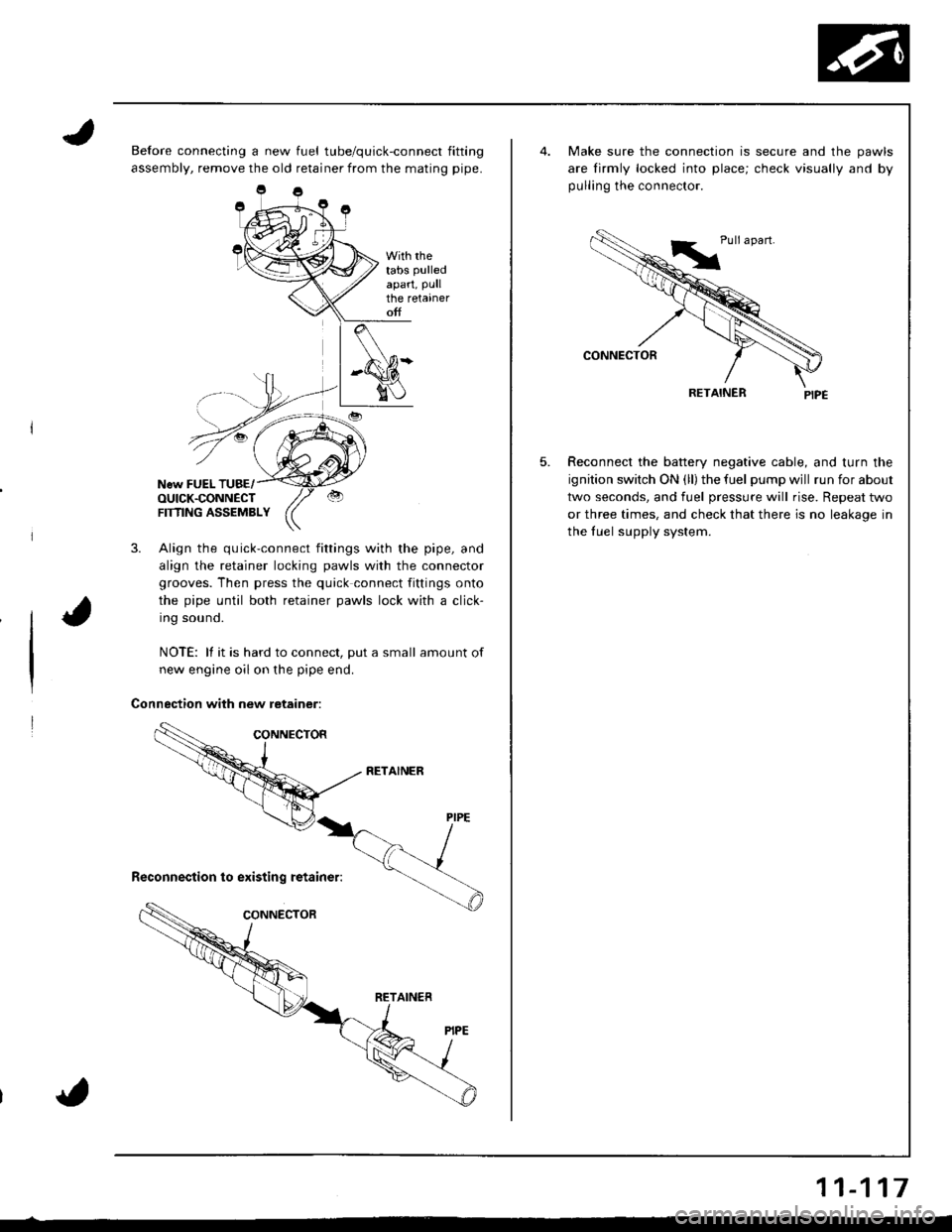
Before connecting a new fuel tube/quick-connect fitting
assembly, remove the old retainer from the mating pipe.
With rhetabs pulled
apart, Pullthe retaineroff
New FUEL TUBE/OUICK.CONNECTFTflNG ASSEMBLY
3. Align the quick-connect fittings with the pipe, and
align the retainer locking pawls with the connector
grooves. Then press the quick connect fittings onto
the pipe until both retainer pawls lock with a click-
Ing souno.
NOTE: lf it is hard to connect, put a small amount of
new engine oil on the pipe end.
Connection with new retainer:
5.
Make sure the connection is secure and the pawls
are lirmly locked into place; check visually and by
pulling the connector.
RETAINER
Reconnect the battery negative cable, and turn the
ignition switch ON (ll) the fuel pump wjll run for about
two seconds, and fuel pressure will rise. Repeat two
or three times, and check that there is no leakage in
the fuel supply system.
11-117
Page 323 of 1681
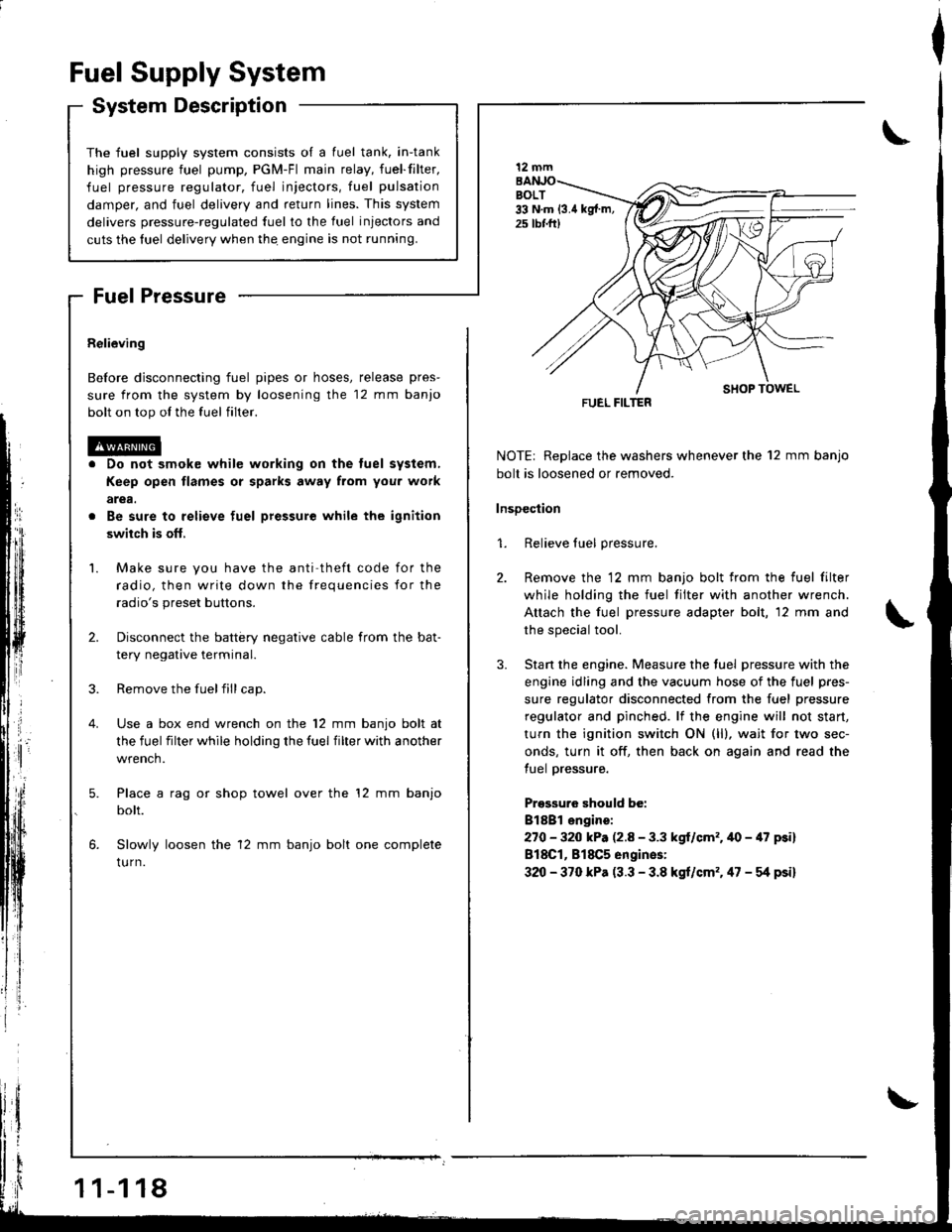
The fuel supply system co
high pressure fuel pump, t
fuel pressure regulator. f
damper, and fuel delivery i
delivers pressure-regulated
cuts the luel delivery when
Fuel Supply System
System Description
consists of a fuel tank, in-tank
r, PGM-Fl main relay, fueffilter,
. fuel injectors, fuel pulsation
y and return lines. This system
ed fuel to the fuel injectors and
rn thq engine is not running.
Fuel Pressure
Relieving
Before disconnecting fuel pipes or hoses, release pres-
sure from the system by loosening the 12 mm banjo
bolt on top ol the fuel filter.
Do not smok€ while working on the tuel system,
Keep open flames or sparks away from you. work
arga.
Be sure to relieve fuel pressure while the ignition
swiich is ofl,
Make sure you have the anti theft code for the
radio, then write down the frequencies for the
radio's preset buttons.
Disconnect the battery negative cable from the bat-
tery negative terminal.
Remove the fuelfill cap.
Use a box end wrench on the 12 mm banjo bolt at
the fuel filter while holding the fuel filter with another
wrench.
Place a rag or shop towel over the '12 mm banjo
bolt.
Slowly loosen the 12 mm banjo bolt one complete
tu rn.
1 1-1 18
I
NOTE| Replace the washers whenever the 12 mm banjo
bolt is loosened or removed.
lnsDection
1. Relieve fuel pressure.
2. Remove the 12 mm banjo bolt from the fuel filter
while holding the fuel tilter with another wrench.
Attach the fuel pressure adapter bolt, 12 mm and
the special tool.
3. Stan the engine. Measure the tuel pressure with the
engine idling and the vacuum hose of the fuel pres-
sure regulator disconnected from the fuel pressure
regulator and pinched. lf the engine will not start,
turn the ignition switch ON (ll), wait for two sec-
onds, turn it off, then back on again and read the
tuel pressure.
Pressuro should be:
Bl8Bl engire:
270 - 320 kP. (2.8 - 3.3 kgl/cm'�.40 - 47 psi)
818C1, 818C5 engines:
320 - 370 kPa (3.3 - 3.8 kgt/cm'�. 47 - g psi)
12 mm
FUEL FILTER
Page 327 of 1681
rr*
Fuel Supply System
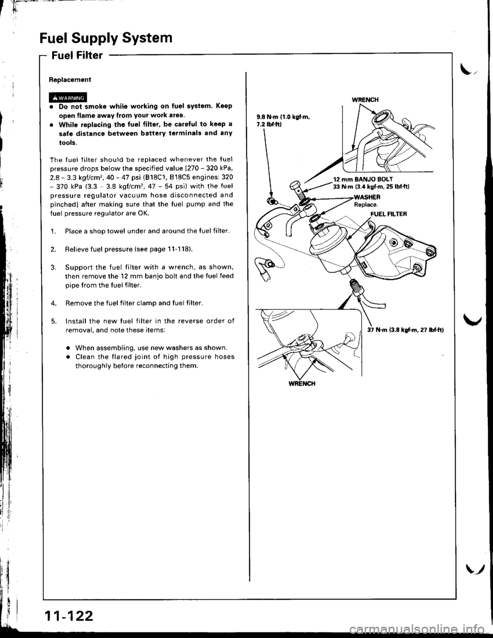
Fuel Filter
Replacement
Do not smoke while working on fuel system. Koop
open flame away from your work atea.
While replacing the fuel filter, be qaretul to keep a
sate distanco between battery terminals and any
tools.
The fuel filter should be replaced whenever the fuel
pressure drops below the specified value I27o - 32O kPa,
2.8 - 3.3 kgf/cm', 40 - 47 psi (B18C'1, B l8C5 enginesi 320- 370 kPa (3.3 - 3.8 kgtcm'�,47 - 54 psi) with the fuel
pressure regulator vacuum hose disconnected and
pinchedl aiter making sure that the tuel pump and the
fuel pressure regulator are OK.
Place a shop towel under and around the fuelfilter.
Relieve fuel pressure {see page 11-1'18}.
Support the fuel filter with a wrench, as shown,
then remove the 12 mm banjo bolt and the tuel feed
pipe lrom the fuelfilter.
Remove the fuel filter clamp and fuel filter.
lnstall the new fuel filter in the reverse order of
removal, and note these items:
. When assembling, use new washers as shown.
. Clean the tlared joint of high pressure hoses
thoroughly before reconnecting them.
\,,
9.8 N.m {1.0 kgf.m,7.2 tbf.frl
WRENCH
12 mm BANJO BOLT33 N.m 13.4 kgf.m. 25 lbl.ftl
37 N.m (3.8 kgf.m,27 lbf.ft)
Page 328 of 1681
'*
1i
v3
I
l
i
I
1.
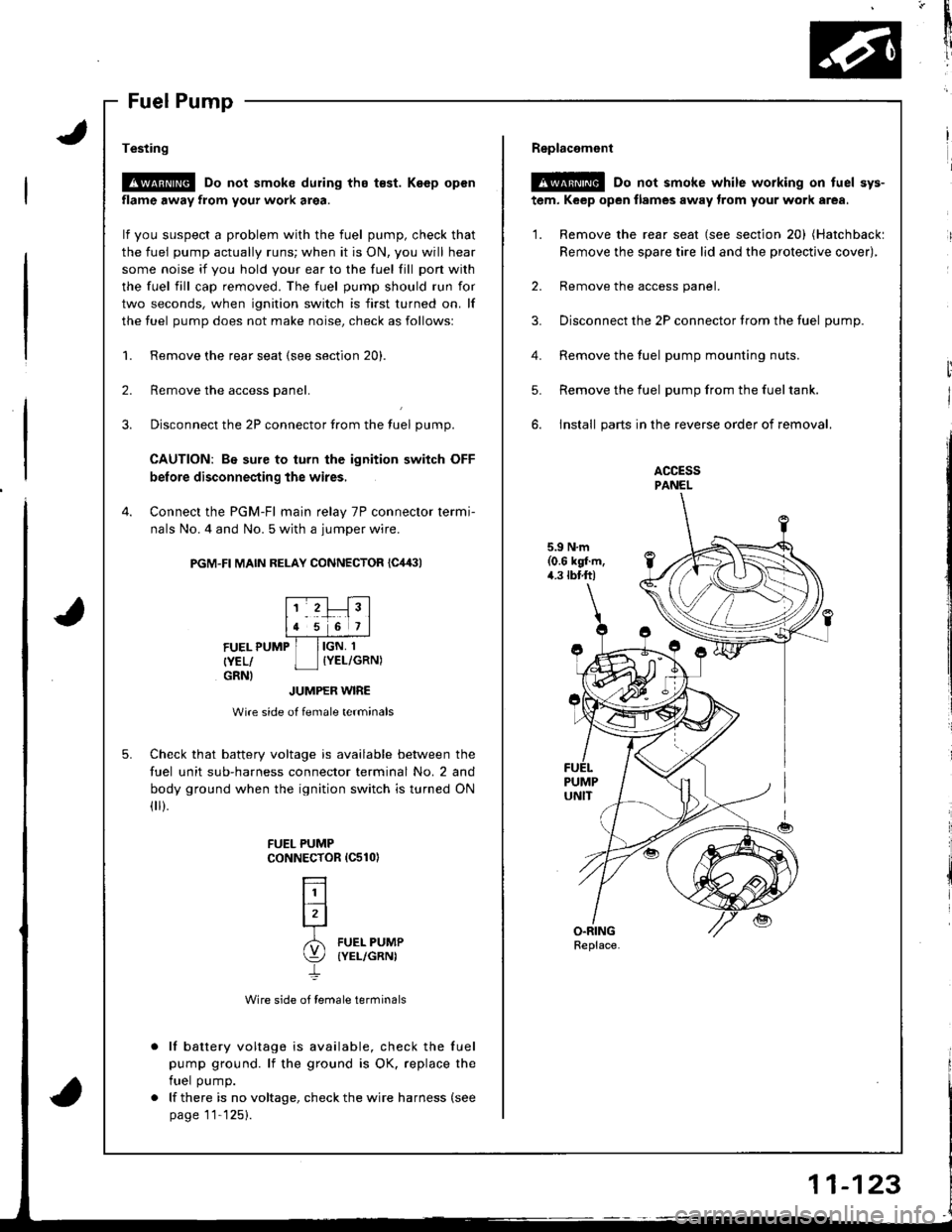
Testing
!@ Do not smoke during tho t€st. Keep open
flame away from your work area.
lf you suspect a problem with the fuel pump, check that
the fuel pump actually runs; when it is ON, you will hear
some noise it you hold your ear to the fuel fill pon with
the fuel fill cap removed. The fuel pump should run for
two seconds, when ignition switch is first turned on. lf
the fuel pump does not make noise, check as followsl
Remove the rear seat (see section 20).
Remove the access panel.
Disconnect the 2P connector from the tuel pump.
CAUTION: Be sure to turn the ignition switch OFF
before disconnecting the wires,
Connect the PGM-Fl main relay 7P connector termi-
nals No. 4 and No. 5 with a jumper wire.
PGM-FI MAIN RELAY CONNECTOR {C,14:}l
2.
3.
4.
5.
FUEL PUMP
{YEL/GRNI
IGN, 1
IYEL/GRN)
JUMPER WIRE
Wire side of female terminals
Check that battery voltage is available between the
fuel unit sub-harness connector terminal No. 2 and
body ground when the ignition switch is turned ON(
).
Wire side of female terminals
lf battery voltage is available, check the fuel
pump ground. lf the ground is OK. replace the
fuel pump.
lf there is no voltage, check the wire harness (see
page 11'125).
FUEL PUMPCoNNECTOR 1C510)
L]l
lrl-r
6l FUEL PUMP
\:/ (YEL/GRNI
4.
Replacemont
@ Do not smoke while working on tuel sys-
tem, Keep open flames away trom your work area.
'1. Remove the rear seat (see section 20) (Hatchbackl
Remove the spare tire lid and the protective cover),
2. Remove the access panel.
3. Disconnect the 2P connector trom the fuel oumD.
Remove the fuel pump mounting nuts.
Remove the fuel pump from the fueltank.
install parts in the reverse order of removal.
ACCESSPANEL
5.9 N.m(0.6 kgl.m,4.3 tbtft)
5.
Replace.