drain bolt HONDA INTEGRA 1998 4.G Workshop Manual
[x] Cancel search | Manufacturer: HONDA, Model Year: 1998, Model line: INTEGRA, Model: HONDA INTEGRA 1998 4.GPages: 1681, PDF Size: 54.22 MB
Page 177 of 1681
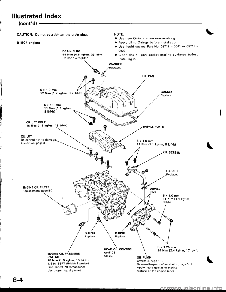
lllustrated Index
(cont'dl
CAUTION: Do not ovenighten the drain plug.
B18C1 engine:
NOTEI
a Use new O rings when reassembling.
a Apply oil to O rings before installation.
. Use liquid gasket, Part No. 08718 0001 or 08718 -
0003.
a Clean the oil pan gasket mating surfaces before
installing it.
WASHERReplace.
DRAIN PLUG44 N.m {4.5 kgf.m,33 lbf.ft)Do not overtighten.
tl
tl
6x LO mm12 N.m {1.2 kgf.m, 8.7 lb{.It}
6 x 1.o mm11 N.m (1.1 kgl.m,8 tbf.fi)
OIL JET BOLT16 N.m {1.6 kgt.m, 13 lbf'ft)
L
III
ij
i
OIL JETBe careful not to damage.lnspection, page 8-9
ENGINE OIL FILTERReplacement, Page 8'7
6 x 1.O mm1 1 N.m (1.1kgf.m,8lbf.Ir)
OIL SCREEN
DOWEL
GASKETReplace.
6x 1.O mm11 N.m {1.1a tbf.ft)k9f.m,
8 x 1.25 mm24 N.m {2.4 kqt'm, 17 lbf.ftlENGINE OIL PRESSUBEswrTcH18 N.m {1.8 kgf.m, 13 lbf.ftl1/8 in. ESPT (Brirish StandardPipe Taper) 28 threads/inch.Use proper liquid gasket.
Overhaul, page 8-10RemovaUlnspection'lnstallation. page 8 11Apply liquid gasket to matingsurtace of the engine block.
8-4
Page 178 of 1681
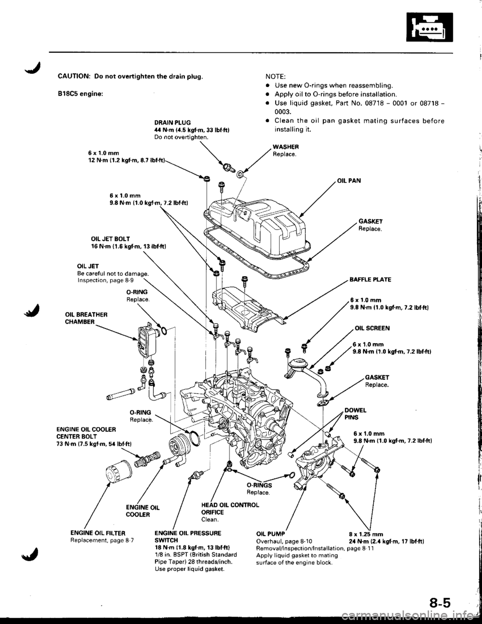
CAUTIONT Do not overtighten the drain plug,
B18C5 engine:
DRAIN PLUG
NOTE:
. Use new O-rings when reassembling.
. Apply oilto O-rings betore installation.
. Use liquid gasket, Part No. 08718 - 0001 or 08718 -
0003.
. Clean the oil pan gasket mating surfaces before
installing it.
WASHERReplace.
OIL PAN
GASKEIReplace.
4,r N.m lia.s kgt m, 33 lbf ftlDo not overtighten.
6x1.0mm12 N.m {1.2 kgI.m,8.7
OIL JET BOLT16 N.m {1.6 kgtm, 13lbf.ttl
\
7.2 tbl.ttl
OIL JETBe carelul not to damage.Inspect;on, page 8 9AAFFLE PLATE
6x1.0mm9.8 N.ft 11.0 kgl.m, 7.2 lbt.ftl
O.RINGReplace.
OIL SCREEN
ENGINE OIL COOLERCENTER BOLT73 N.m {?.5 kgf.m,5a lbt.ftl
ENGINE OIL FILTERReplacement, page I7
Replace.
OIL CONTROL
6x1.0mm9.8 N.m lr.0 kgt ft,7.2lbtftl
GASKETReplace.
8 x 1.25 mm2,1 N.m (2.1 kgt m, 17 lbf.ftl
DOWELPINS
6x1.0mm9,8 N.m 11.0 kgtm,7.2lbf.ftl
ORIFICEClean.
ENGINE OIL PRESSUREswrTcH18 N.m 11.8 kgt.m, 13 lbtft)1/8 in. BSPT (British StandardPipe TaDer) 28 threads/inch.Use proper liquid gasket.
OIL PUMPOverhaul, page 8-10Removal/lnspection/lnstallation, page 8 1 1Apply liquid gasket to matingsurface of the engine block.
Page 200 of 1681
Radiator
Engine Coolant Refilling and Bleeding
CAUTION: When pouring engine coolant, be sure to shut
th6 relay box lid and not to l€t coolant spill on th6 el€c-
trical parts or the paint. lf any coolant spills, rinse it off
immediately.
1. Slide the heater temDerature control lever to maxi-
mum heat.
Make sure the engine and radiator are cool to the
touch.
2. Remove the radiator cap.
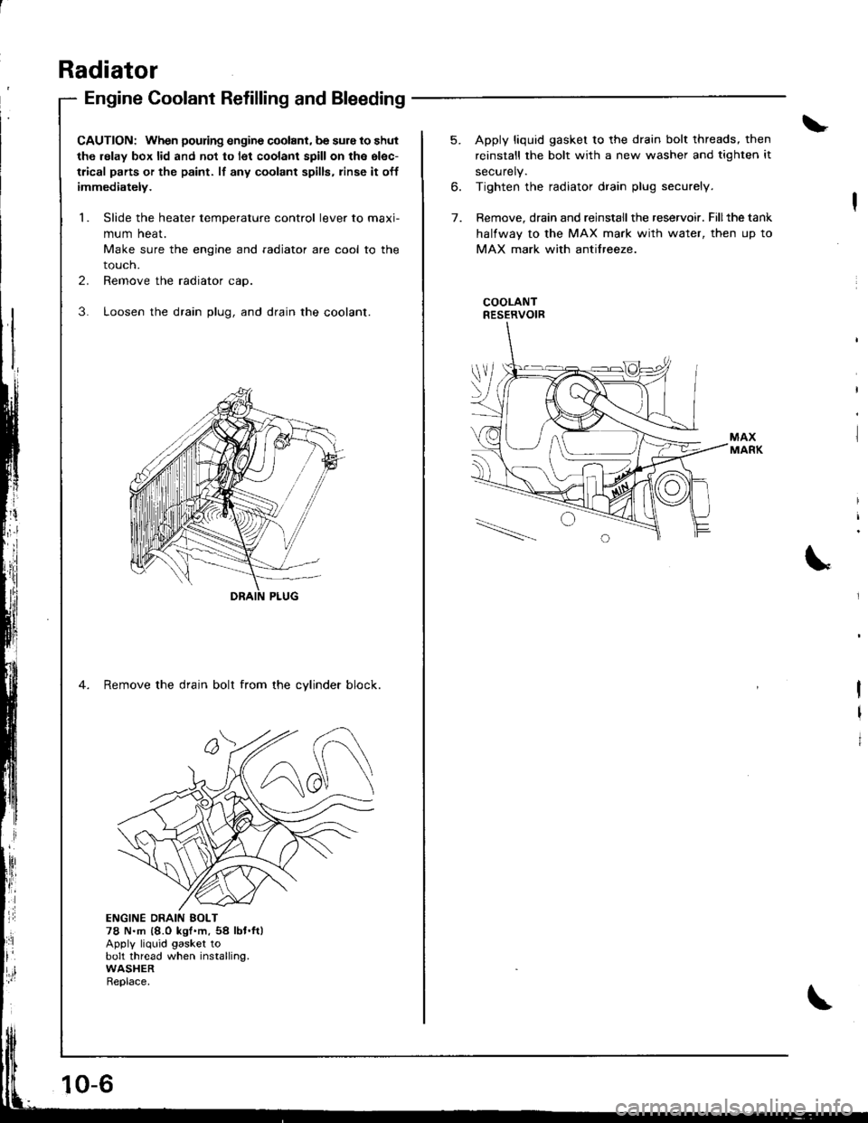
3. Loosen the drain plug, and drain the coolant.
4. Remove the drain bolt from the cvlinder block.
ji
Ii'
l:ll
ENGINE DRAIN EOLT78 N.m {8.0 kgt'm,54 lbt.ft)Apply liquid gasket tobolt thread when installing.WASHERReplace.
10-6
5. Apply liquid gasket to the drain bolt threads, then
reinstall the bolt with a new washer and tighten it
securely.
6. Tighten the radiator drain plug securely.
7. Remove, drain and reinstall the reservoir. Fillthe tank
halfway to the MAX mark with water, then up to
MAX mark with antifreeze.
COOLANTRESERVOIR
I
I
I
Page 332 of 1681
1r
;
J
I
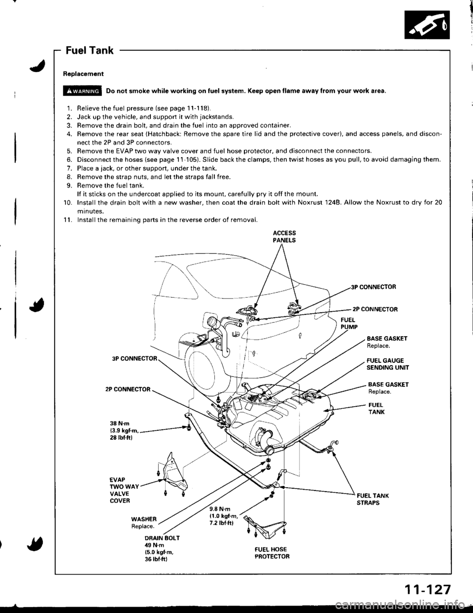
Fuel Tank
Reolacement
!!@ Do not smoke while working on fuel system. Keep open flame away from your work a.ea.
1. Relieve the fuel pressure(seepagell-118).
2. Jack up the vehicle, and support it with jackstands.
3. Remove the drain bolt, and drain the fuel into an approved container.
4. Remove the rear seat (Hatchbackt Remove the spare tire lid and the protective cover), and access panels, and discon-
nect the 2P and 3P connectors.
5. Remove the EVAP two way valve cover and fuel hose protector, and disconnect the connectors.
6. Disconnect the hoses (see page 11-105). Slide back the clamps, then twist hoses as you pull, to avoid damaging them.
7. Place a tack, or other support, under the tank.
8. Remove the strap nuts, and let the straps fall free.
9. Remove the fuel tank.
lf it sticks on the undercoat applied to its mount, carefully pry it offthe mount.
10. lnstallthe drain bolt with a new washer, then coat the drain bolt with Noxrust 1248. Allow the Noxrust to dry tor 20
minutes.
11. Installthe remaining parts in the reverse order of removal.
ACCESSPANELS
CONNECTOR
2P CONNECTOR
3P CONNECTOR
2P CONNECTOR
EASE GASKETReplace.
FUEL GAUGESENDING UNIT
BASE GASKETReplace.
FUELTANK
38 N.m13.9 kgtm,28 tbf.ftl
EVAPTWO WAYVALVECOVERFUEL TANKSTNAPS
WAS}IERReplace.
9.8 N.m{1.0 kgf.m,7.2 tbt.tll
ORAIN BOLTilg N.m(5.0 k9f.m.36 rbf.ftl
FUEL HOSEPROTECTOR{
11-127
Page 374 of 1681
I
T
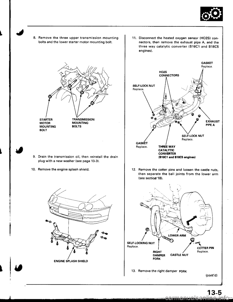
Remove the three upper transmission mounting
bolts and the lower starter motor mountino bolt.
STARTERMOTOEMOUNTINGBOLT
Drain the transmission oil, then reinstall the drainplug with a new washer (see page 13-3).
Remove the engine splash shield.10.
11.
6tr!
/
SELF.LOC1(ING NUTReplace.
Disconnect the heated oxygen sensor (HO2S) con-
nectors, then remove the exhaust pipe A. and the
three way catalytic converter (B'18C1 and B18C5
engines).
Feplace. THREE WAYCATALYNCCONVERTENlg18C1 lnd 818C5 onginrsl
Remove the cotter pins and loosen the castle nuts,
then separate the ball joints from the lower arm(see sectiotr'l8).
LOWER ARM
DAMPER CASTLE NUTFORK
13. Remove the right damper FORK
(cont'd)
13-5
Page 420 of 1681
Description
\J
t{
{
14-3
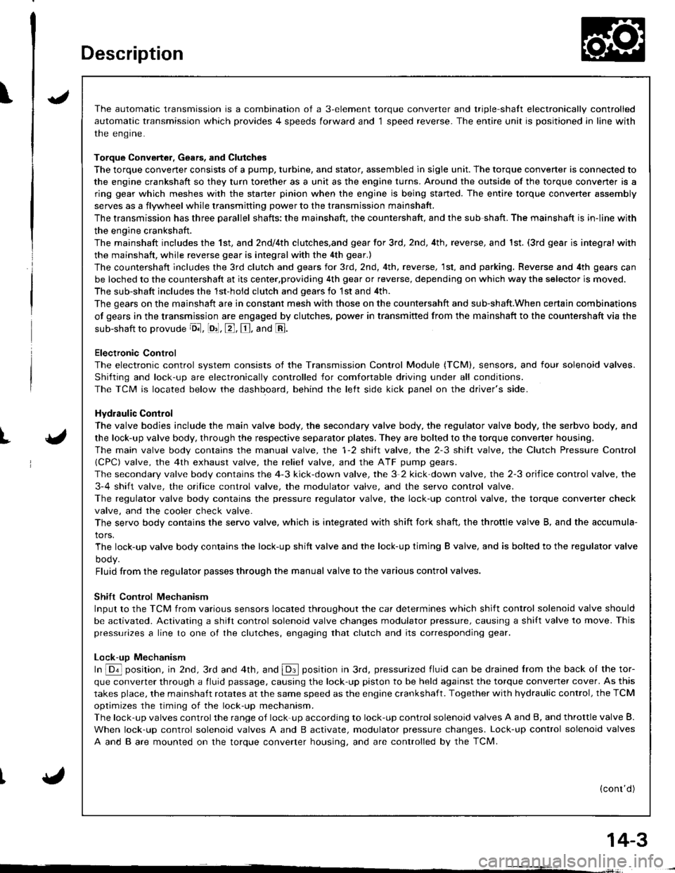
The automatic transmission is a combination of a 3-element torque converter and triple-shalt electronically controlled
automatic transmission which provides 4 speeds forward and 1 speed reverse. The entire unit is positioned in line with
the engrne.
Torque Converter, Gears, and Clutches
The torque converter consists of a pump, turbine, and stator, assembled in sigle unit. The torque converter is connected to
the engine crankshaft so they turn torether as a unit as the engine turns. Around the outside of the torque convener is a
ring gear which meshes with the starter pinion when the engine is being started. The entire torque converter assembly
serves as a flywheel while transmitting power to the transmission mainshaft.
The transmission has three parallel shafts; the mainshaft. the countershaft, and the sub shaft. The mainshaft is in-line with
the engine crankshaft.
The mainshaft includes the 1st, and 2ndl4th clutches,and gear for 3rd, 2nd, 4th, reverse, and 1st. (3rd gear is integral with
the mainshaft, while reverse gear is integral with the 4th gear.)
The countershaft includes the 3rd clutch and gears for 3rd,2nd, 4th, reverse, 1st, and parking. Reverse and 4th gears can
be loched to the countershaft at its center,providing 4th gear or reverse, depending on which way the selector is moved.
The sub-shaft includes the 1st-hold clutch and gears fo 1st and 4th.
The gears on the mainshaft are in constant mesh with those on the countersahft and sub-shaft.When certain combinations
of gears in the transmission are engaged by clutches. power in transmitted from the mainshaft to the countershaft via the
sub-shaft to orovude oil, lo'1. E, E. and E.
Electronic Control
The electronic control svstem consists of the Transmission Control Module (TCM), sensors, and four solenoid valves.
Shilting and lock-up are electronically controlled for comfortable driving under all conditions.
The TCM is located below the dashboard, behind the lelt side kick panel on the driver's side.
Hydraulic Control
The valve bodies include the main valve body, the secondary valve body, the regulator valve body, the serbvo body, and
the lock-up valve body, through the respective separator plates, They are bolted to the torque converter housing,
The main valve body contains the manual valve, the 1-2 shift valve, the 2-3 shitt valve, the Clutch Pressure Control
lCPC) valve, the 4th exhaust valve, the reliel valve, and the ATF pump gears.
The secondary valve body contains the 4-3 kick-down valve, the 3-2 kick-down valve, the 2-3 orifice control valve, the
3-4 shift valve, the orilice control valve, the modulator valve, and the servo control valve.
The regulator valve body contains the pressure regulator valve, the lock-up control valve, the torque converter check
valve, and the cooler check valve.
The servo body contains the servo valve, which is integrated with shift fork shaft, the throttle valve B, and the accumula-
tors.
The lock-up valve body contains the lock-up shift valve and the lock-up timing B valve, and is bolted to the regulator valve
ooqy.
Fluid from the regulator passes through the manual valve to the various control valves.
Shift Control Mechanism
Input to the TCM from various sensors located throughout the car determines which shift control solenoid valve should
be activated. Activating a shitt control solenoid valve changes modulator pressure, causing a shift valve to move. This
pressurizes a line to one ol the clutches, engaging that clutch and its corresponding gear.
Lock-uD Mechanism
In @ position, in 2nd, 3rd and 4th, and @ position in 3rd, pressurized fluid can be drained lrom the back oI the tor-
que converter through a fluid passage, causing the lock-up piston to be held against the torque converter cover. As this
takes place, the mainshaft rotates at the same speed as the engine crankshaft. Together with hydraulic control, the TCM
optimizes the timing of the lock-up mechanism.
The lock-up valves controlthe range of lock-up according to lock-up control solenoid valves A and B, and throttle valve B.
When lock-up control solenoid valves A and B activate, modulator pressure changes. Lock-up control solenoid valves
A and B are mounted on the torque converter housing, and are controlled by the TCM.
(cont'd)
Page 522 of 1681
8.
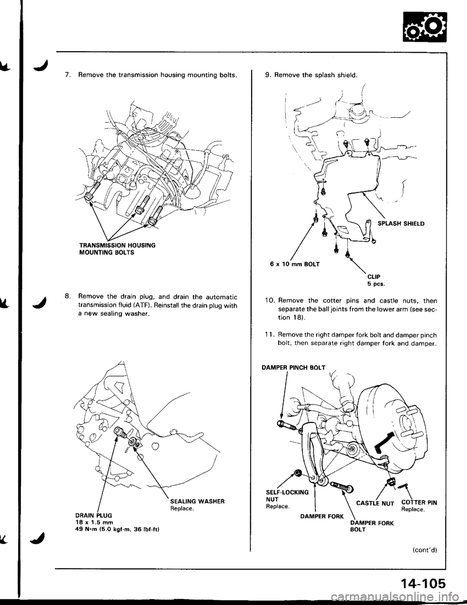
7. Remove the transmission housing mounting bolts.
Remove the drain plug, and drain the automatictransmission fluid {ATF). Reinstallthe drain plug with
a new sealing washer.
18 x 1.5 mm49 N.m {5.O kgt-m,36 lbf-fr)
V.
9. Remove the splash shield.
SPLASH SHIELD
6 x 10 mm BOLT
CLIP5 pcs.
10. Remove the cotter pins and castle nuts, then
separate the balljoints from the lower arm (see sec-
tion 18).
1 1 . Remove the right damper fork bolt and damper pinch
bolt, then separate right damper tork and damper.
PINCH BOLT
SELF.LOCKINGNUTReplace.
a
COTTER PINReplace.DAMPEB FORK
14-105
Page 526 of 1681
L
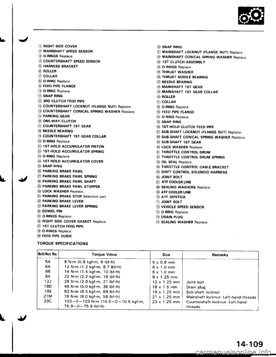
(t RtcHT sroE covER
@ MAINSHAFT sPEEo sENsoR(O O-RINGS Reptace.
@ couNTERSHAFT spEEo sENsoR
@ HARNESS BRACKET
@ RoLLER
O coLLAR
@ O-RING Replace.
@ FEEo PIPE FLANGE
@ o-RtNG Reptace.
O) SNAP RING
@ 3RD cLUTcH FEED PIPE
@ COUNTERSHAFT LocKNUT (FLANGE NUT) RepIace,
@ couNTERSHAFT CONtcAL spRtNG wAsHER Reptace.
@ PARKING GEAR
G) ONE-WAY cLUTcH
@ COUNTERSHAFT lST GEAR
@ NEEoLE BEARTNG
@ COUNTERSHAFT 1ST GEAR COLLAR
€0 o-RING Reprace.
@ 1sT-HoLD AccUMULAToR ptsTok
@ 1sr-HoLD AccUMULAToR spRtNG
@ o-RING Reptace.
@ rsr-HoLD AccUMULAToR covER
@ SNAP RING
@ PARKING BRAKE PAWL
@ PARKING BRAKE PAWL SPRING
€0 PARKTNG BRAKE PAWL SHAFT
@ PARKTNG BRAKE pawl sroppER
€0 LOCK WASHEF Replace.
@ PARKTNG BRAKE STOP Setecrive oart
@ PARKING BRAKE LEVER
@ PARKING ERAKE LEVER SPRING
@ DowEL PrN
@ o-RlNGs Reptace.
@ RtcHT StOE COVER GASKET Reptace.
@ 1sr cLUTcH FEED ptpE
@ O-R|NGS Reptace.
@ FEEO P|PE GUTOE
TOROUE SPECIFICATIONS
@ SNAP R|NG
@ MAINSHAFT LocKNUT (FLANGE NUT) Replace
@ MAtNSHAFT coNtcAL spRtNG wAsHER Reptace.
@ 1sT clurcH ASSEMBLY
@ O-RINGS Reptace.(4D THRUST wASHEB
@ THRUST NEEDLE EEARING
@) NEEDLE EEARING
@ MAINSHAFT 1sT GEAB
@ MAINSHAFT ,IsT GEAR coLLAR
@ ROLLER
€) coLLAR
@ o-R|NG Reptace.
@ FEED PIPE FLANGE
@ o-RtNG Reptace.
@ SNAP RING
@ 1sT-HoLD cLUTcH FE€D ptpE
@ SUB-SHAFT LOCKNUT TFLANGE NUT) Reptace.
@ suB-SHAFT CONTCAL SpRtNG WASHER Reptace.
@ SUB-SHAFT 1sT GEAR
@ LocK WASHER Reptace.
@ THRoTTLE coNTRoL DRUM
6, THRoTTLE coNTRoL DRUM SPRING
@ OIL SEAL Replace.
@ THRoTTLE coNTRoL cAELE BRAGKET
@ sHtFT coNTRoL soLENoto HARNESS
G0) JOINT BOLT
@ ATF COOLER LINE
@ SEAL|NG wASHERS Reptace.
@ ATF cooLER LINE
@ ATF DrPsflcK
@ JOINT BoLT
@ vEHrcLE SPEED sENsoR
@ o-RING Reptace.
(, DRAIN PLUG
@ SEAL|NG wasHER Replace.
Bolti Nut No.Torque ValueSizeRemarks
5A
6A
6B
8A
12J
18D
r9s
21M
23C
8 N.m (0.8 kgf.m, 6 lbf'ft)
12 N.m (1.2 kgf.m,8.7 lbf.ft)
14 N.m { 1 .4 kgf .m, 1 0 lbf .ft)
22 N'm 12.2 kgf 'm, 16 lbf .ft)
28 N.m (2.9 kgf.m. 2'1 lbl.It)
49 N.m {5.O kgl.m, 36 lbf.tt)
93 N.m (9.5 kgt.m, 69 lbf.tt)
78 N.m (8.0 kgt.m, 58 lbf .ft)
103-O- 103 N.m (1O.5 - O- 10.5 kgf.m.7 5.9 - O- 75.9 tbt.ft)
5xO.8mm
6 x 1.O mm
6 x 1.O mm
8 x 1.25 mm
12x1.25mm
18 x 1.5 mm
19 x 1.25 mm
2t x |.25 mm
23 x 1.25 mm
Joint bolt
Drain plug
Sub-shaft locknut
Mainshaft locknut: Left-hand threads
Countershaft locknut: Left hand
threads
{l
14-109
Page 634 of 1681
t
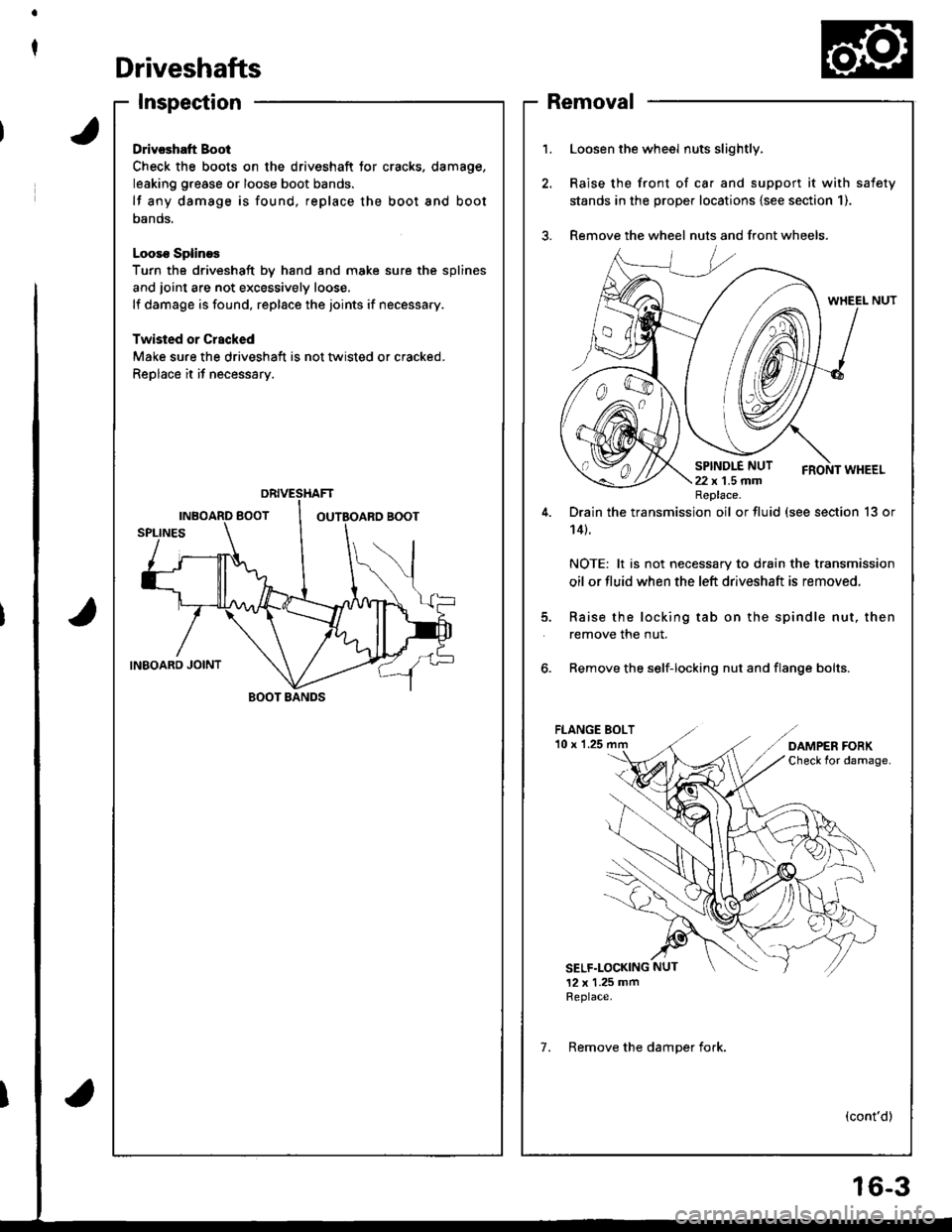
Driveshafts
Inspection
Drivcshatt Boot
Check the boots on the driveshaft tor cracks. damage,
leaking grease or loose boot bands.
lf any damage is found, replace the boot and boot
oanos.
Looso SplineE
Turn the driveshaft by hand and moke sure the splines
and joint are not excessively loose.
lf damage is found, replace the joints if necessary.
Twisled or Crscked
Make sure the driveshaft is not tlvisted or cracked.
Replace it if necessary.
BOOT BANDS
1.Loosen the wheel nuts slightly,
Raise the front of ca. and support it with safety
stands in the prope. locations {see section 1).
Remove the wheel nuts and front wheels.
5.
Drain the transmission oil or fluid (see section 13 or
14t.
NOTE: lt is not necessary to drain the transmission
oil or fluid when the left driveshaft is removed.
Raise the locking tab on the spindle nut, then
remove the nut.
6. Remove the self-locking nut and flange bolts.
FLANGE BOLT'10 x 1.25
SELF.LOCKING NUT
12 x 1.25 mmReplace.
(cont'd)
Replace.
7. Remove the damoer fork.
Removal
6-3
Page 646 of 1681
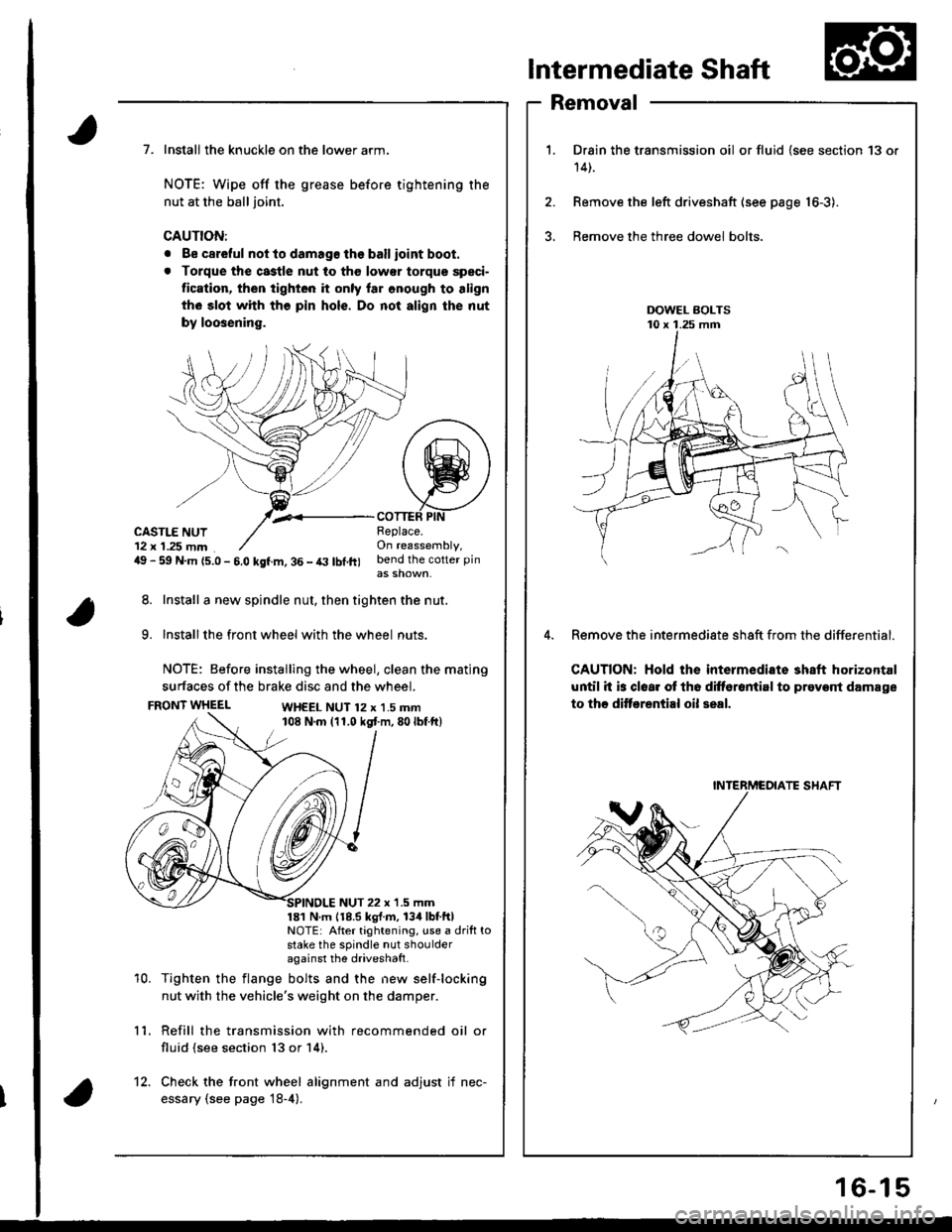
Intermediate Shaft
Removal
Drain the transmission oil or fluid {see section 13 or
14t.
Remove the left driveshaft (see page 16-3).
Bemove the three dowel bolts.
Remove the intermediate sh8ft from the differential.
CAUTION: Hold the intermediate shaft horizontal
until it is clear ot th6 difforantirl to prevont damage
to thc ditf€rential oil seal.
7. Install the knuckle on the lower arm.
NOTE: Wipe off the grease before tightening the
nut at the ball joint.
CAUTION:
. Be careful not to damago the ballioint boot.
. Torque the castle nut to tho low€r torque speci-
tication, then tighten it only lar onough to align
th6 slot whh tho pin hols. Do not align the nut
by loosening.
,.<__coTTEF PtNCASTLE NUT12 x 1.25 mm49 - 59 N.m {5.0 - 5.0 kgf.m, 36 - t3 lbl.ft)
Beplace.On reassembly,bend the cotter pin
8. Install a new spindle nut, then tighten the nut.
9. Installthe front wheel with the wheel nuts.
NOTE: Before installing the wheel, clean the mating
surfaces of the brake disc and the wheel.
FRONT WHEELWH€EL NUT 12 x 1.5 mm108 N.m (11.0 kgt m,80lbf ft)
10.
NUT 22 x '1.5 mm181 N m 118.5 kgl.m, 134lbtftlNOTE: After tightening, use a drift tostake the spindle nut shoulderagainst the driveshatt.
Tighten the flange bolts and the new self-locking
nut with the vehicle's weight on the damper.
Refill the transmission with recommended oil or
fluid (see section 13 or 14).
11.
12. Check the front wheel alignment and adjust if nec-
essary (see page 18-4).
INTERMCOIATE SHAFT
16-15