fuse box location HONDA INTEGRA 1998 4.G User Guide
[x] Cancel search | Manufacturer: HONDA, Model Year: 1998, Model line: INTEGRA, Model: HONDA INTEGRA 1998 4.GPages: 1681, PDF Size: 54.22 MB
Page 1085 of 1681
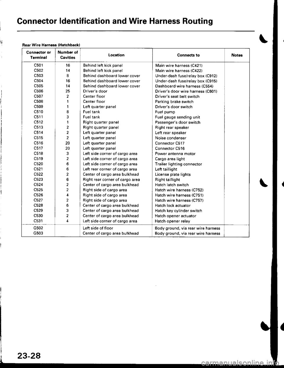
Gonnector ldentification and Wire Harness Routing
Rear Wire Harngss {Hatchbackl
Connector or
Terminal
Number of
C8vitiesLocationConnec{s toNotos
c501
c502
c504
c505
cs06
c507
c508
c509
c510
c51 1
c512
c513
c514
c515
uc to
c518
c519
c520
c522
c524
c528
c529
c530
c531
l6
14
8
16
14
2
1
I
8
3
1
2
2
2
20
20
2
2
6
2
2
2
3
4
Behind left kick panel
Behind left kick panel
Behind dashboard lower cover
Behind dashboard lower cover
Behind dashboard lower cover
Driver's door
Center floor
Center floor
Left quarter panel
Fuel tank
Fuel tank
Right quarter panel
Right quarter panel
Left quarter panel
Left quarter panel
Left quaner panel
Left quarter panel
Left side corner of cargo area
Left side corner of cargo area
Left side corner of cargo area
Left rear corner of cargo area
Center of cargo area bulkhead
Right rear corner of cargo area
Center of cargo area bulkhead
Right side of cargo area
Right side of cargo area
Right side of cargo area
Center of cargo area bulkhead
Center of cargo area bulkhead
Center of cargo area bulkhead
Left side corner of cargo area
Main wire harness {C421)
Main wire harness {C422)
Underdash fuse/relay box (C912)
Underdash fuse/relay box (C915)
Dashboard wire harness (C554)
Driver's doo. wire harness (C601)
Driver's seat belt switch
Parking brake switch
Driver's door switch
Fuel pump
Fuel gauge sending unit
Passenger's door switch
Right rear speaker
Left rear speaker
Noise condenser
Connector C517
Connector C516
Power antenna motor
Cargo area light
Trailer lighting connector
Left taillight
License plate lights
Right taillight
Hatch latch switch
Hatch wire harness (C752)
Hatch wire harness (C751)
Hatch wire harness (C757)
Hatch lock actuator
Hatch key cylinder switch
Hatch opener actuator
Hatch opener relay
Left side of floor
Center of cargo area bulkhead
Body ground, via rear wire harness
Body ground. via rear wire harness
riI
Page 1087 of 1681
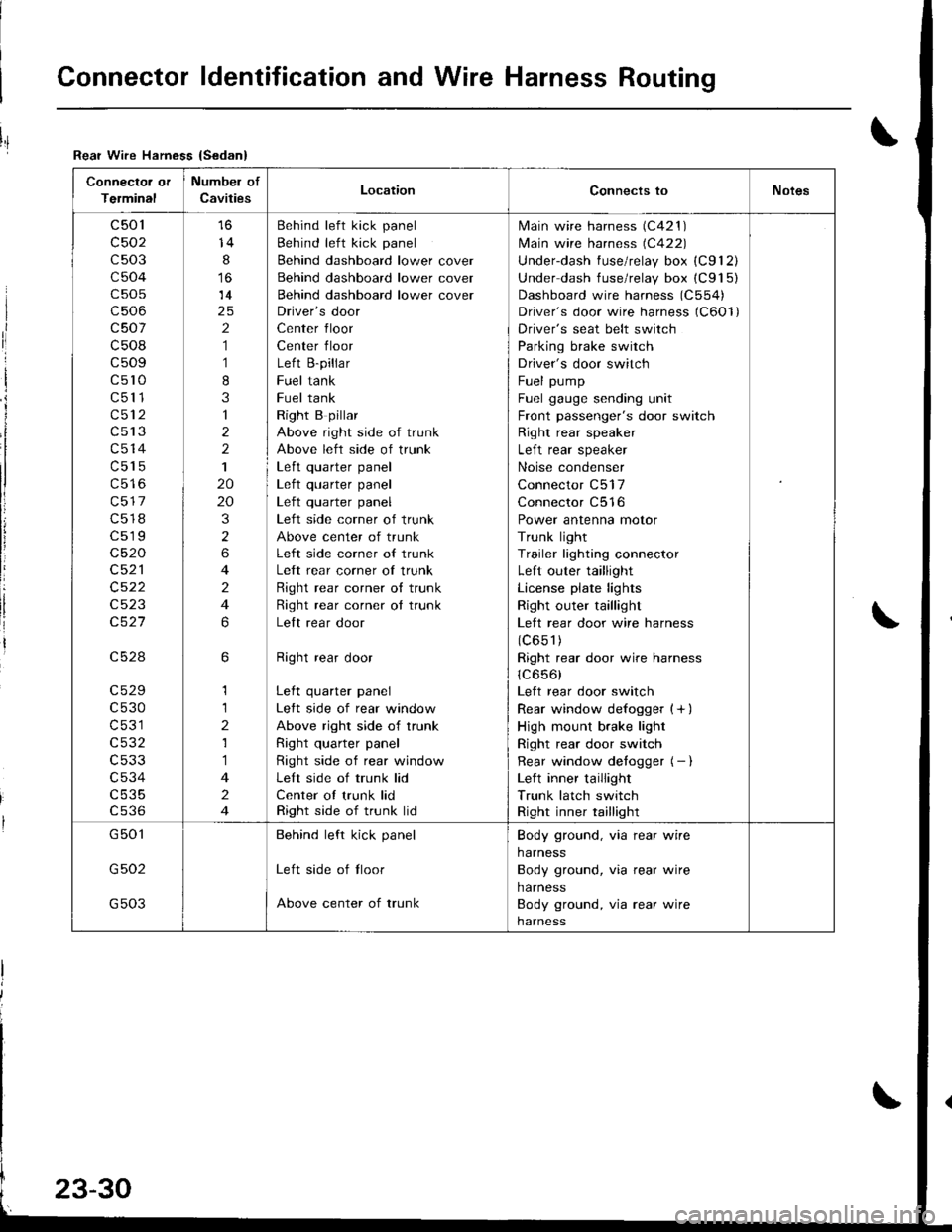
Connector ldentification and Wire Harness Routing
Connector or
Terminal
Numbel of
CavitiesLocationConnects toNotes
c501
c502
c503
c504
c505
c506
c507
c508
c509
c5l0
c511
c512
c513
c514
c515
c517
c518
c519
c520
c521
c522
c523
c527
c528
c529
c530
c531
c532
c533
c534
c535
cs36
14
8
14
2
1
1
8
3
1
2
2
1
20
20
3
2
6
4
2
4
6
6
1
1
2
1
1
4
2
4
Behind left kick panel
Behind left kick panel
Behind dashboard lower cover
Behind dashboard lower cover
Behind dashboard lower cover
Driver's door
Center floor
Center floor
Left B-pillar
Fuel tank
Fuel tank
Right B pillar
Above right side of trunk
Above left side of trunk
Left quarter panel| .{+ ^',rrrar ^rnal
Left quarter panel
Left side corner of trunk
Above center of trunk
Left side corner of trunk
Left rear corner of trunk
Right rear corner o{ trunk
Right rear corner ot trunk
Lelt rear door
Right rear door
Left quarter panel
Left side of rear window
Above right side of trunk
Right quarter panel
Right side of rear window
Left side of trunk lid
Center of trunk lid
Right side of trunk lid
lvlain wire harness (C421 )
lvlain wire harness (C422)
Underdash fuse/relay box (C912)
Under dash fuse/relay box (C915)
Dashboard wire harness (C554)
Driver's door wire harness (C6Ol)
Driver's seat belt switch
Parking brake switch
Driver's door switch
Fuel pump
Fuel gauge sending unit
Front passenger's door switch
Right rear speaker
Left rear speaker
Noise condenser
Connector C517
Connector C516
Power antenna motor
Trunk light
Trailer lighting connector
Left outer taillight
License plate lights
Right outer taillight
Lett rear door wire harness
(c651)
Right rear door wire harness
1C656)
Left rear door switch
Rear window defogger {+ )
High mount brake light
Right rear door switch
Rear window detogger (- I
Left inner taillight
Trunk latch switch
Right inner taillight
G501
G502
G503
Behind left kick panel
Left side of tloor
Above center of trunk
Body ground, via rear wire
harness
Body ground, via rear wire
harness
Body ground, via rear wire
harness
Rear Wire Hamess {Sedan}
I
ri
I
i
I
li
!
Page 1089 of 1681
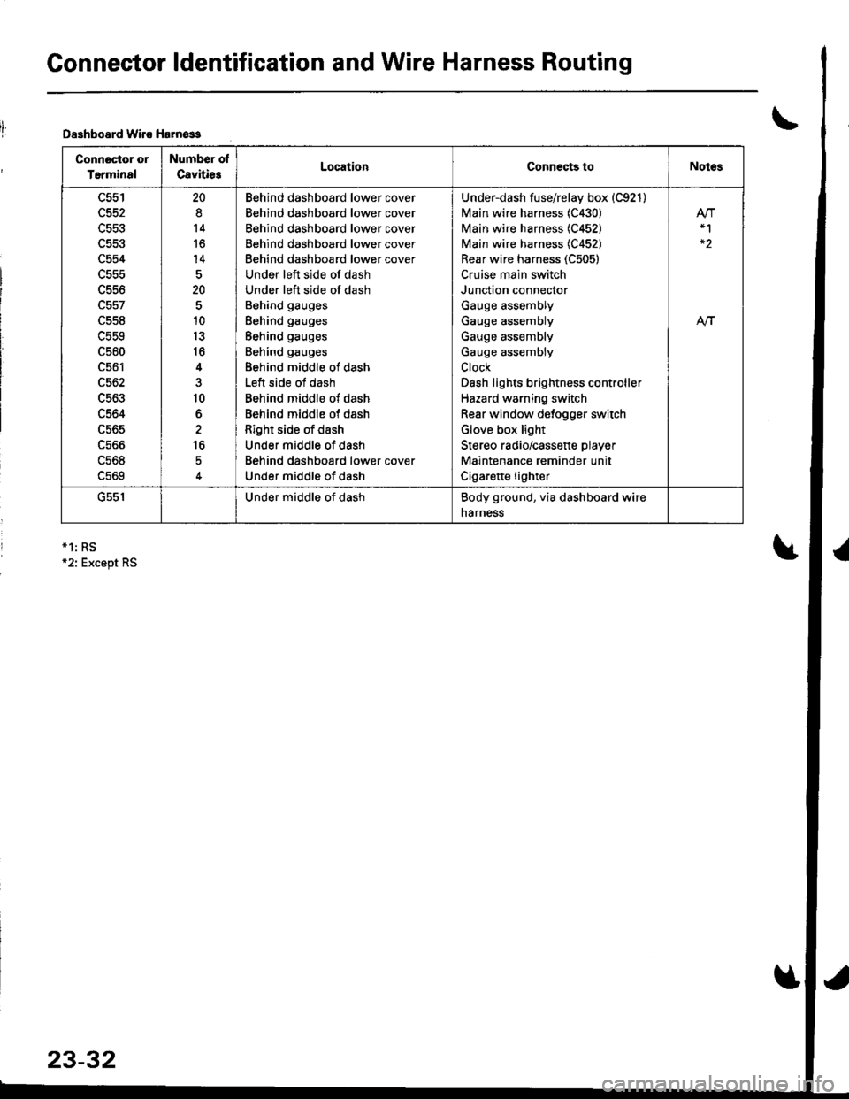
Connector ldentification and Wire Harness Routing
Dsshboard lvirc Harn€ss
Connoctor or
Terminal
Number ol
Cavitie3LocationCoDnects toNotes
c554
L55t'
c561
c562
c563
c564
c565
ucoo
uc06
c569
20
8
14
to
14
20
10
13
16
4
10
6
16
Behind dashboard lower cover
Behind dashboard lower cover
Behind dashboard lower cover
Behind dashboard lower cover
Behind dashboard lower cover
Under left side of dash
Under left side of dash
Behind gauges
Behind gauges
Behind gauges
Behind gauges
Behind middle of dash
Left side of dash
Behind middle of dash
Behind middle of dash
Right side of dash
Under middle of dash
Behind dashboard lower cover
Under middle of dash
Under-dash fuse/relay box (C921)
Main wire harness (C430)
Main wire harness (C452)
Main wire harness (C452)
Rear wire harness (C505)
Cruise main switch
Junction connector
Gauge assembly
Gauge assembly
Gauge assembly
Gauge assembly
Clock
Dash lights brightness controller
Hazard warning switch
Rear window defogger switch
Glove box light
Stereo radio/cassette player
Maintenance reminder unit
Cigarette lighter
At-|-
uc5 |Under middle of dashBody ground, via dashboard wire
narness
*1: RS12: Except RS
23-32
Page 1097 of 1681
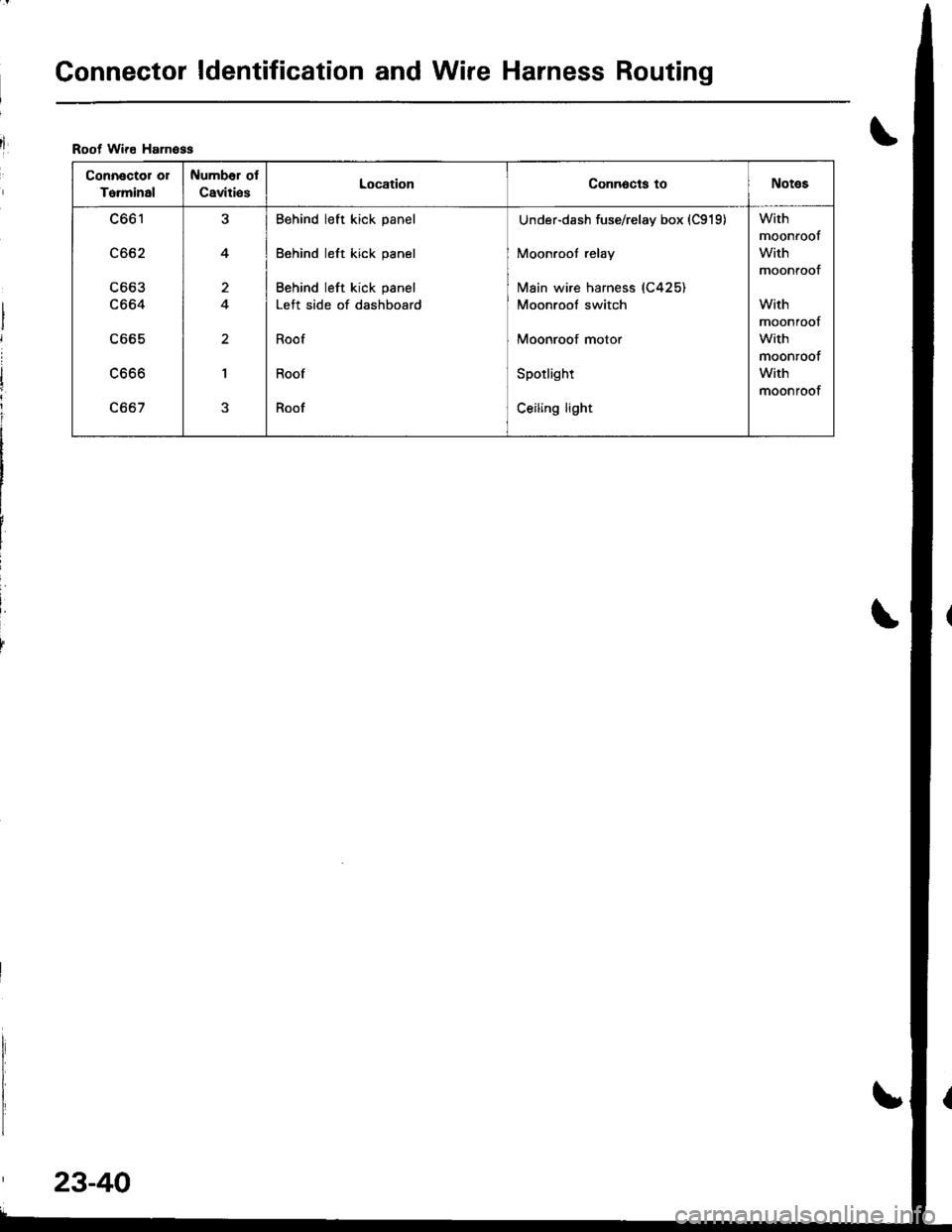
Gonnector ldentification and Wire Harness Routing
Root Wire Hamoss
Connector or
To.minal
Number ol
Caviti€sLocationConnocts toNotes
c661
c662
c663
c664
c665
LOOO
c667
J
4
a
I
Behind left kick panel
Behind left kick panel
Behind left kick panel
Left side of dashboard
Roof
Roof
Roof
Under-dash fuse/relay box (C919)
Moonroof relay
lvlain wire harness (C425)
Moonroof switch
Moonroof motor
Spotlight
Ceiling light
With
moonroof
With
moontoof
With
moonroof
with
moonroof
With
moonroof
23-40
Page 1104 of 1681
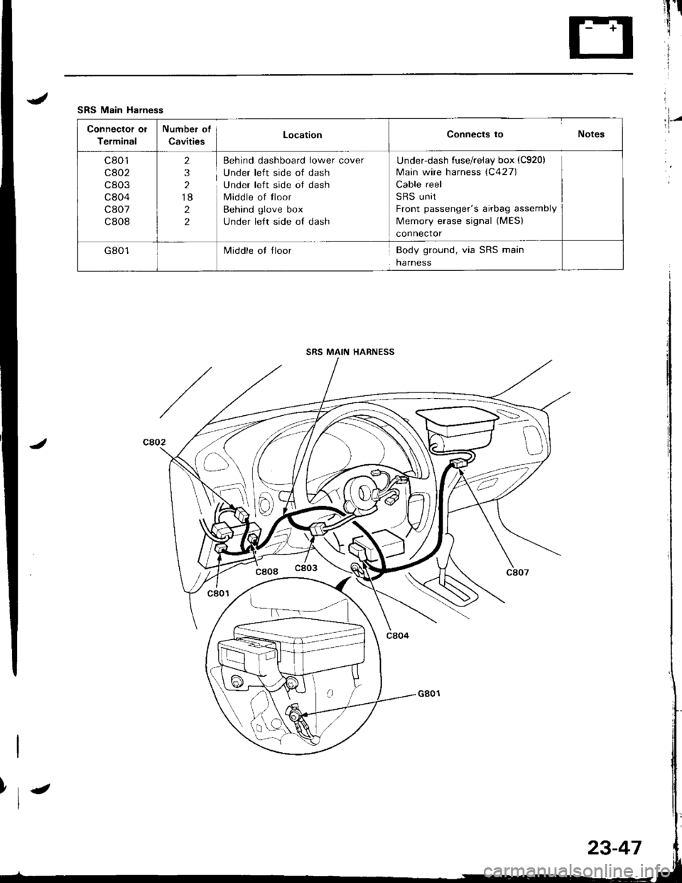
.lI
SRS Main Harness
Connector ol
Terminal
Number of
CavitiesLocationConnects to Notes
c801
cao2
c803
c804
c807
c808
2
3
2
18
2
2
Behind dashboard lower cover
Under left side of dash
Under left side of dash
Middle of tloor
Behind glove box
under le{t side of dash
Underdash fuse/reiay box (C920)
Main wire harness (C427)
Cable reel
SRS unit
Front passenger's airbag assembly
Memory erase signal (MES)
connector
G801Middle ot floorBody ground, via SRS main
harness
I,l-/
SRS MAIN HARNESS
>\-
D
23-47
Page 1128 of 1681
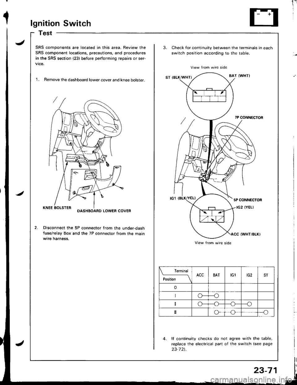
1lgnition Switch
Test
J
J
SRS components are located in this area. Review the
SRS component locations. precautions, and procedures
in the SRS section (23) before performing repairs or ser-
vtce.
'I . Remove the dashboard lower cover and knee bolster.
3.Check for continuity between the terminals in each
switch position according to the table.
View from wire side
ST IBLK/WHT}BAT (WI{TI
7P CONNECTOR
5P CONNECTOR
IG2 (YELIDASHBOARD LOWER COVER
Disconnect the 5P connector from the under-dash
fuse/relay box and the 7P connector from the mainwrre harness.IWHT/BI-K}
4. ll continuity checks do not agree with the table,
replace the electrical part of the switch {see page
23-7 2).
View from wire side
Terminal
PositionACCBATtGlrG2ST
o
o---o
o--_o
0o---o
23-71
Page 1129 of 1681
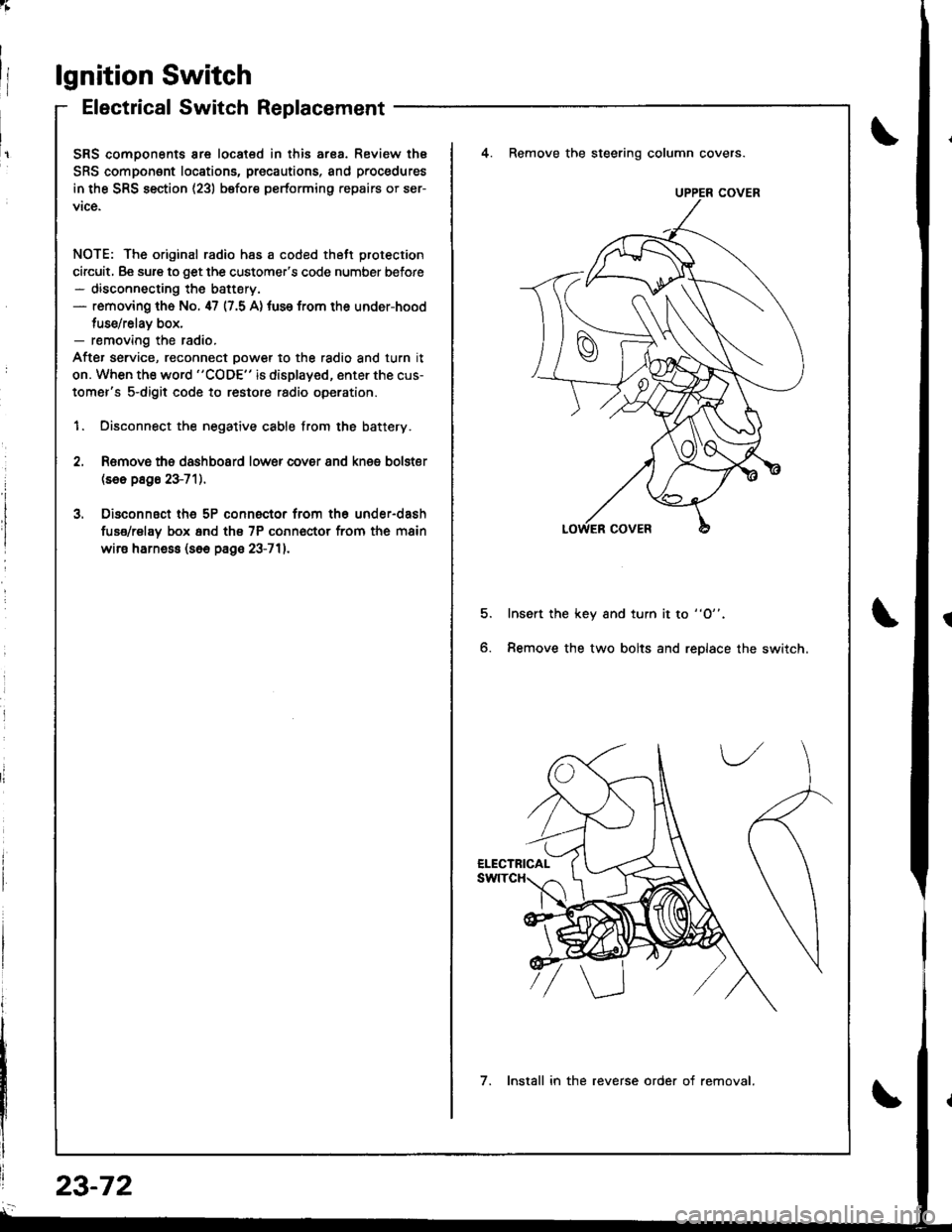
lgnition Switch
Electrical Switch Replacement
SRS comoonents are located in this ar8a. Review thE
SRS component locations, precautions, and procedures
in the SRS section (23) before performing repairs or ser-
vice.
NOTE: The original radio has a coded thett protection
circuit, Be sure to get the customer's code number before- disconnecting the battery.- removing th6 No. 47 (7.5 A) tuse from the under-hood
tuse/relav box,- removing the radio.
After service, reconnect oower to the radio and turn it
on. When the word "CODE" is displayed, enter the cus-
tomer's s-digit code to restore radio operation.
1. Disconnect the negative cable from the battery.
4. Remove the steering column covers.
Romovs ths dashboard lower cover 8nd knes bolster(se6 p8g6 23-71).
Disconnsct th6 5P connector from th6 under-dash
fuse/rel8y box 6nd th€ 7P conn€ctor from the main
wire harne$ (s6e page 23-711.
5.Insert the key and turn it to "O".
Remove the two bolts and replace the switch6.
UPPER COVER
7. Install in the reverse order of removal.
23-72
Page 1130 of 1681
;
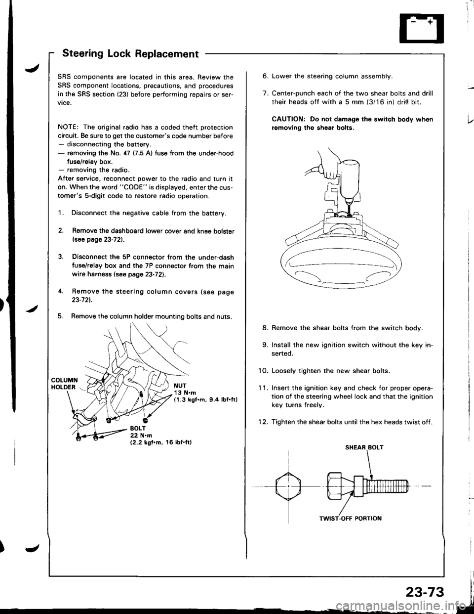
Steering Lock Replacement
SRS components are located in this area. Review the
SRS component locations, precautions, and procedures
in the SRS section (23) before performing repairs or ser-
vice.
NOTE: The original radio has a coded theft protection
circuit. Be sure to get the customer's code number before- disconnecting the battery.- removing the No. 47 (7.5 A) fuse trom the under-hood
fuse/relav box.- removing the radio.
After service, reconnect power to the radio and turn it
on. When the word "CODE" is displayed. enter the cus-
tomer's 5-digit code to restore radio operation.
1. Disconnect the negative cable from the battery.
2. Remove ths dsshboard lower cover and knee bolster(s6o p8ge 23-72).
3, Disconnect the 5P connector from the under-dash
fuse/relay box and the 7P connsctor from th€ main
wire harness (see page 23-72l.,
4. Remove the steering column covars (see page
23-721.
5. Remove the column holder mounting bolts and nuts.
NUT13 N.m(1.3 kgl.m, 9.4 lbt.ftl
BOLT22 N.m(2.2 kgf.m, 16 lbf.ftl
6.
7.
Lower the stee.ing column assembly.
Center-ounch each of the two shear bolts and drill
their heads oft with a 5 mm {3/16 in) drill bit.
CAUTION: Do not damage the switch body when
lemoving th€ sheal bolts.
Remove the shear bolts from the switch body.
Install the new ignition switch without the key in-
serted.
1O. Loosely tighten the new shear bolts.
11. Ins€rt the ignition key and check for proper opera-
tion of the sleering wheel lock and that the ignition
key turns freely.
12. Tighten the shear bolts until the hex heads twist off.
8.
Page 1156 of 1681

)
)
Charging System
Component Locationlndex
CHARGING SYSTEM LIGHT(ln the gauge assembly)Test, pages 23-102,103Bulb Locations, page 23-122
UNDER-HOOD FUSE/RELAY BOX(USA: HAS bUiIt-iN ELECTRICALLOAD DETECTOR (ELD) UNIT}Troubleshooting of ELD, secrion 11
BATTERYTest,
ALTERNATOR BELTInsp€ction and Adiustment, page 23_115ALTERNATORTroubleshooting, page 23'102Alternator/FegulatorTosl, pages 23-105,'106Replacement, page 107Overhaul, page 23-108
23-99
.t-
Page 1173 of 1681
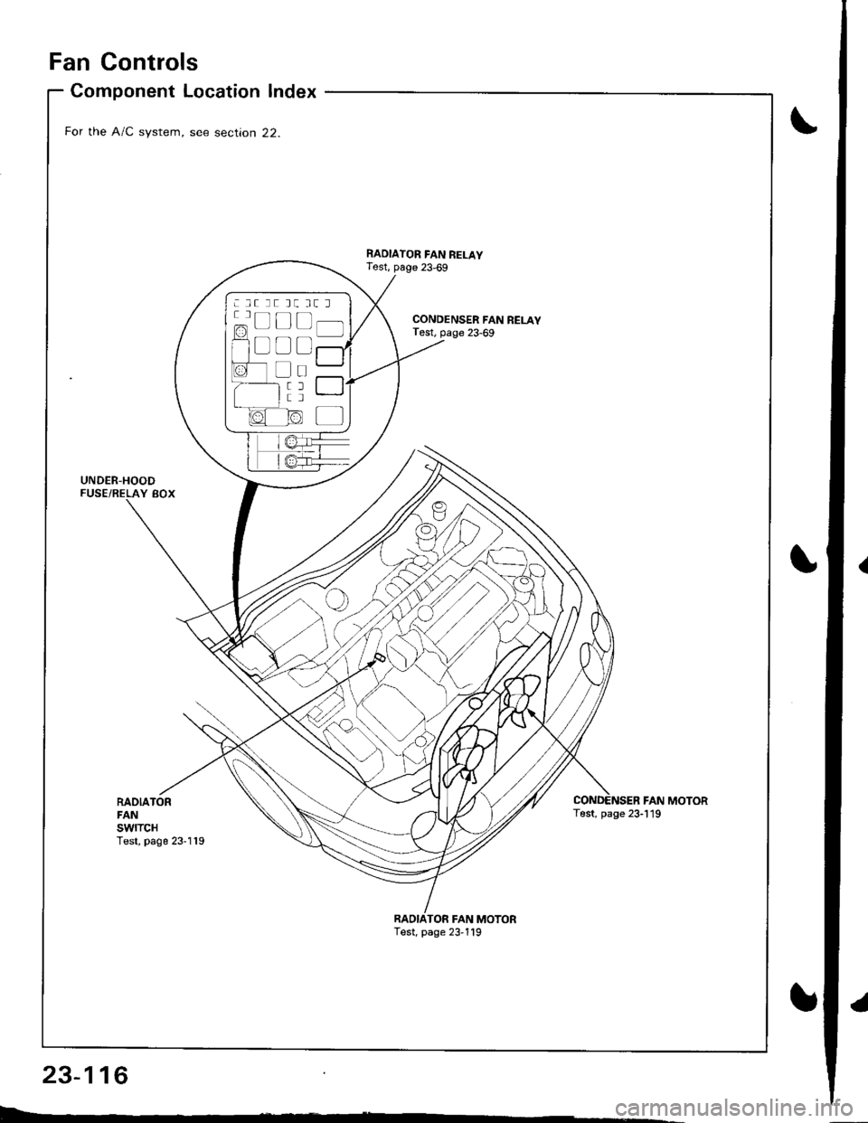
Fan Controls
RADIATORFANswtTcHTest, page 23-119
Component Location Index
For the A/C system, see section 22.
UNDER-HOODFUSE/RELAY BOX
CONDENSER FAN RELAYTest, page 23-69
RADIATOR FAN RELAYTest, page 23,69
FAN MOTORTest, page 23-119
TOR FAN MOTORTest, page 23,119
: lt tt tt tt l
c=, Ll L-t t lf l]-]l
f1 a l f -r a'r -
I i I r""""rlla-t fr -
a tL) | |Irt -
1/^ l/-\ltr.z{ N/ L