gearbox HONDA INTEGRA 1998 4.G User Guide
[x] Cancel search | Manufacturer: HONDA, Model Year: 1998, Model line: INTEGRA, Model: HONDA INTEGRA 1998 4.GPages: 1681, PDF Size: 54.22 MB
Page 668 of 1681
I
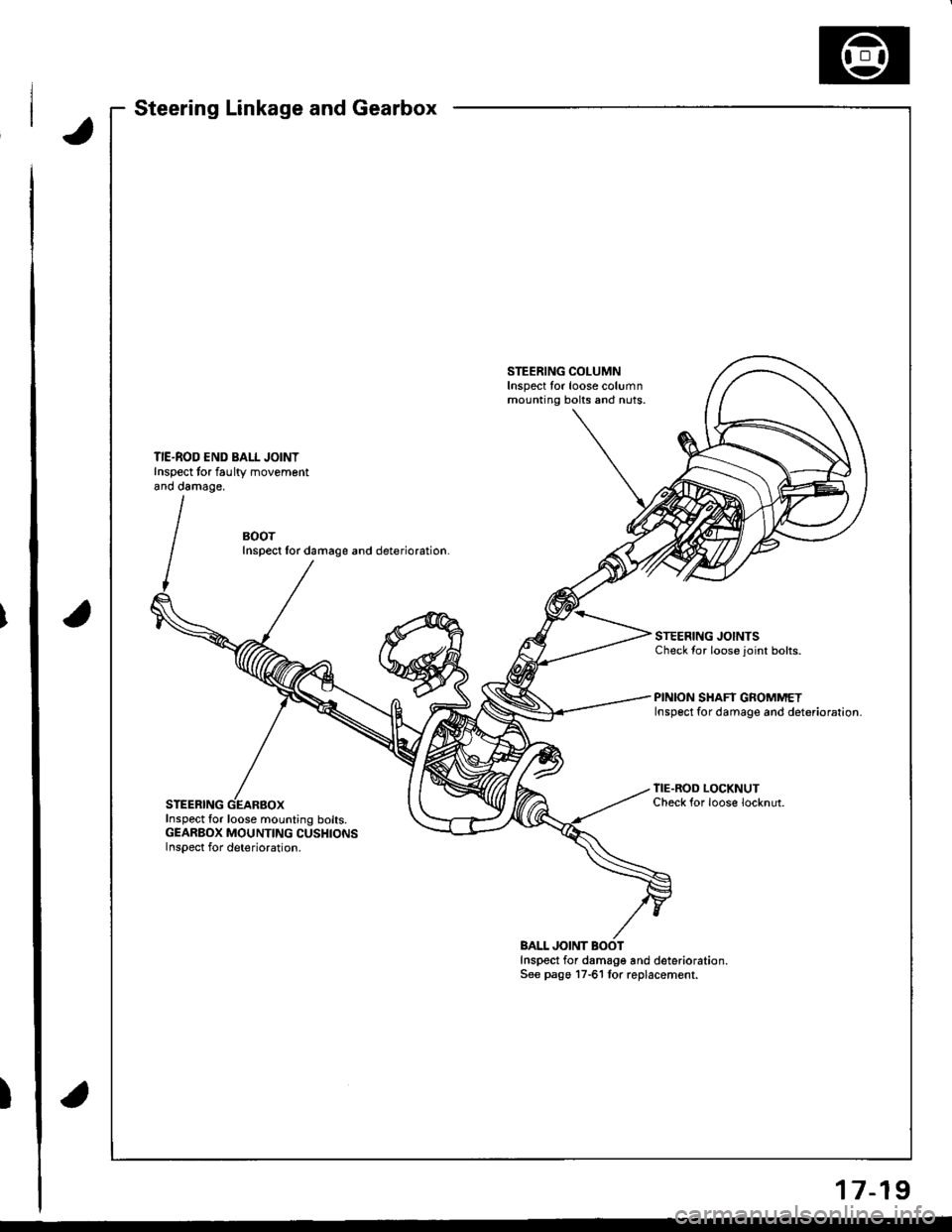
Steering Linkage and Gearbox
STEERING COLUMNInspect tor loose columnmounting bolts and nuts.
TIE.ROD END BALL JOINTInspect tor faultv movementano oamage,
BOOTInspect lor damage and deterioration.
STEERING JOINTSCheck {or loose joint bolts.
PINION SHAFT GROMMETInsp6ct for damage and deterioration.
STEERING
TIE.ROD LOCKNUTCheck {or loose locknut.
Inspect for loose mounting bolts.GEARBOX MOUNTING CUSHIONSInspect for deterioration.
BALL JOINTInspect for damage and deterioration.See pago 17-61 lor replacement.
17-19
Page 671 of 1681
Inspection and Adjustment
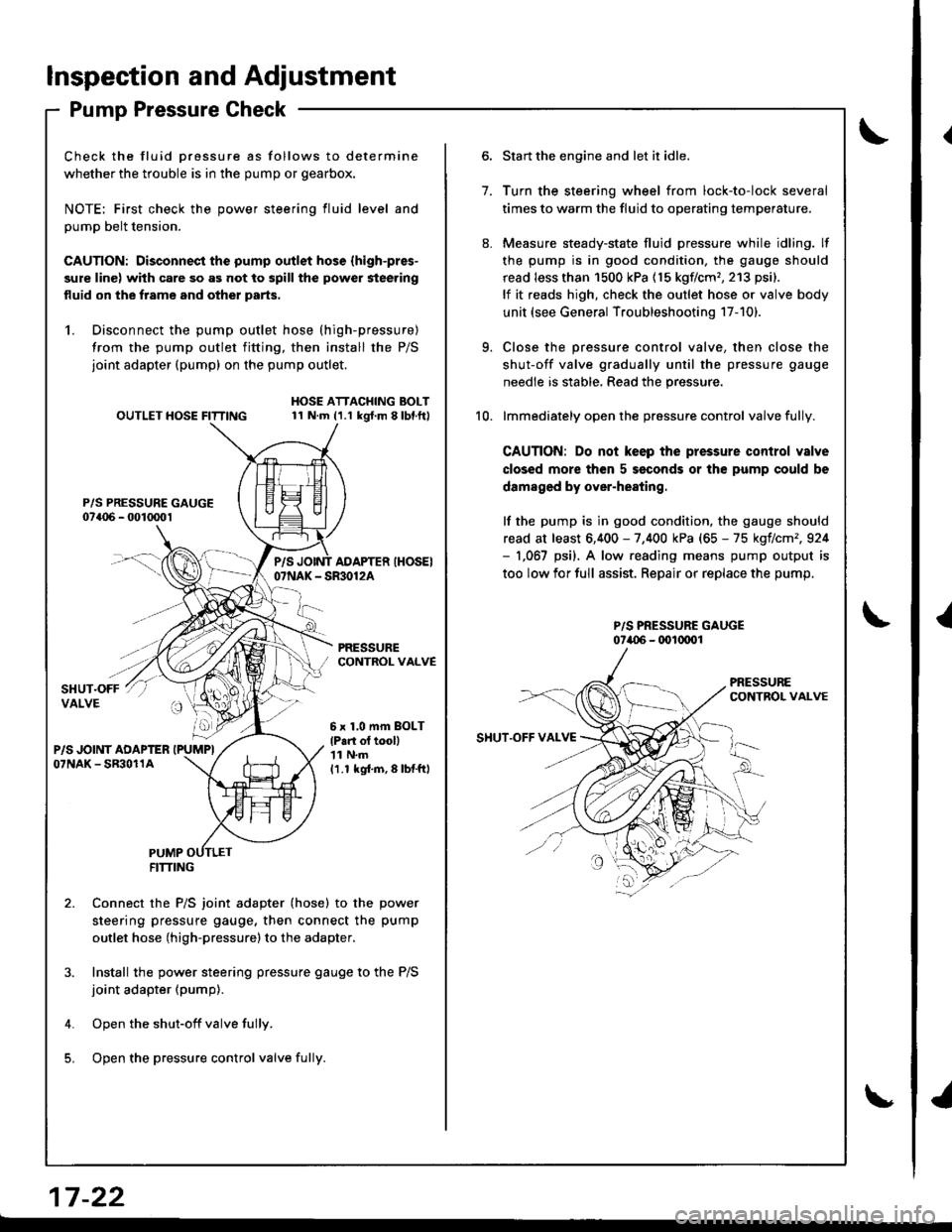
Pump Pressure Check
Check the fluid Dressure as follows to determine
whether the trouble is in the pump or gearbox.
NOTE; First check the power steering fluid level and
pump belt tension.
CAUTION: Disconnect the pump outlet hose (high-pres-
sure line) with care so as not to spill the power steering
fluid on the frame and other parts,
1. Disconnect the pump outlet hose (high-pressure)
from the pump outlet fitting, then install the P/S
joint adapter (pump) on the pump outlet.
P/S PRESSURE GAUGE07a06 - 001mo1
OUTLET HOSE FITTINGHOSE ATTACHING BOLT11 N.m (1.1 kgt.m 8lbl.ft)
PRESSURECONTROL VALVE
P/SAOAPTER IHOSEI07NAK - SR30124
6 x 1,0 mm BOLT
lP.n ol tooll'| 1 N.m
11.1 kgi.m,8lbtftl
PUMPFITTING
Connect the P/S joint adapter (hose) to the power
steering pressure gauge, then connect the pump
outlet hose (high-pressure)to the adapter.
Install the power steering pressure gauge to the P/S
joint adapter (pump).
Open the shut-off valve fully.
Open the pressure control valve fulli.
1.
Start the engine and let it idle.
Turn the steering wheel from lock-to-lock several
times to warm the fluid to operating temperature.
Measure steady-state fluid pressure while idling. lf
the pump is in good condition, the gauge should
read less than 1500 kPa (15 kgflcm'�,213 psi).
lf it reads high, check the outlet hose or valve body
unit (see General Troubleshooting 17-101.
Close the pressure control valve, then close the
shut-off valve gradually until the pressure gauge
needle is stable, Read the pressure.
lmmediately open the pressure control valve fully.
CAUTION: Do not keep the pressure control valve
closed more then 5 seconds or the pump could be
damaged by over-heating.
lf the pump is in good condition, the gauge should
read at least 6,400 - 7,400 kPa (65 - 75 kgflcm',924- 1,067 psi). A low.eading means pump output is
too low for full assist. Repair or replace the pump.
P/S PRESSURE GAUGE07i.{)6 - (x)l(xrol
9.
10.
SHUT.OFF VAI.VE
17 -22
{
I
Page 672 of 1681
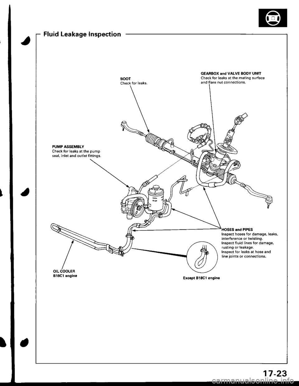
Fluid Leakage Inspection
BOOTCheck for Ieaks.
GEARBOX and VALVE BOoY UNITCheck tor leaks at the mating surfaceand Ilare nut connections,
PUMP ASSEMBLYCheck Ior leaks at the pumD
seal, inlet and outlet fittings.
Inspect hoses for damage, leaks,interfe re n ce or twisting,Inspect fluid lines for damage,rusting or leakage.Inspect for leaks at hose andline ioints or connections.
Bl8Cl engineExc.pl 818Cl engine
17-23
Page 690 of 1681
Power Steering
Gearbox
Removal
NOTE: Using solvent and a brush, wash any oil and dirt
off the valve body unit, its lines, and the end if the gear-
box. Blow dry with compressed air.
l. Drain the power steering fluid as described on page
11-21.
2. Raise the front of vehicle, and support on safety
stands in the proper locations (see section 1).
3. Remove the front wheels.
4. When the vehicle is equipped with the SBS airbag
system, remove the steering wheel (see page 17-
24t.
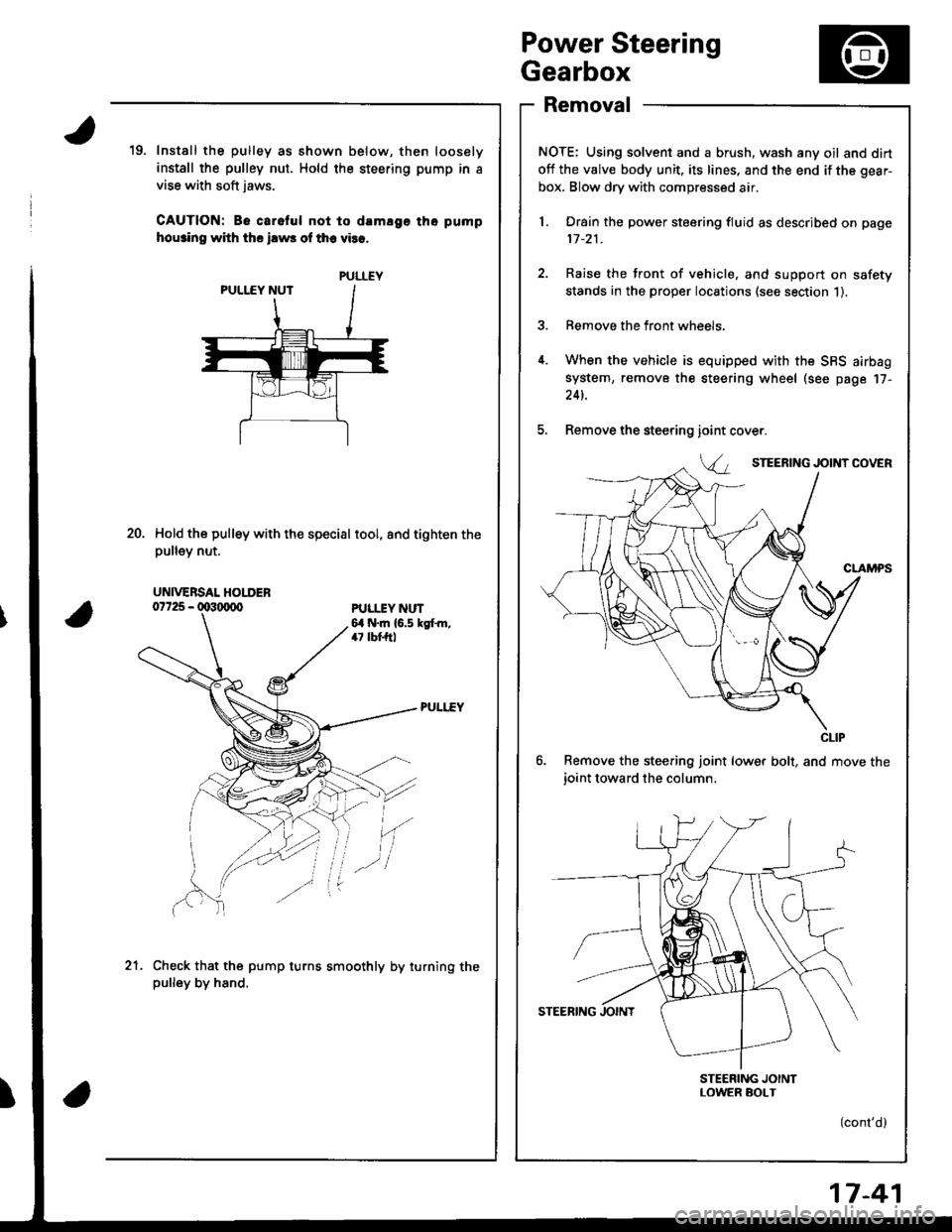
5. Remove the steering
6. Remove the steering joint lower bolt, and move the
ioint toward the column.
STEERING JOINTLOWER SOI-T
(cont'd)
19. Install the pulley as shown below, then loosely
install the pulley nut. Hold the steering pump in a
vise with soft jaws.
CAUTION: Be carelul not to damlge tho pump
hou3ino with ths ilws of th6 vies.
Hold the pulley with the special tool, and tighten thepu ey nut.
ioint
Va
20.
PULI.IY NUT6,1 N.m {6.5 kgt m,47 lbf,ftl
'(
Check that the pump turns smoothly by turning thepulley by hand.
.-l
21.
PULLEY
UNIVERSAL HOLDER
CLIP
17-41
Page 691 of 1681
Power Steering Gearbox
Removal (cont'd)
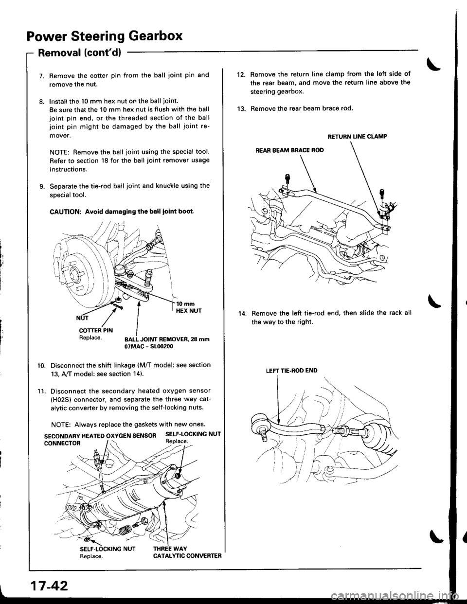
Remove the cotter pin from the ball joint pin and
remove the nut.
Install the 10 mm hex nut on the ball ioint.
Be sure that the 10 mm hex nut is flush with the ball
joint pin end, or the threaded section of the ball
joint pin might be damaged by the ball joint re-
mover.
NOTE: Remove the ball joint using the special tool.
Refer to section 18 for the ball joint remover usage
instructions.
Separate the tie-rod ball ioint and knuckle using the
special tool.
CAUTION: Avoid damaging th. ball ioint boot.
t{ePrace. BALL JOINT REMOVER,23 mm07MAC - SL0020o
10. Disconnect the shift linkage (M/T model: see section
13, A,/T model: see section 14).
11. Disconnect the secondary heated oxygen sensor
(H02Sl connector, and separate the three way cat-
alytic convener by removing the self-locking nuts.
NOTE: Always replace the gaskets with new ones.
SECONDARy HEATED OXycEN SENSOR SELF-LOCKING NUT
17 -42
Replace.CATAI.YTIC CONVERTER
12.
13.
Remove the return line clamp from the left side of
the rear beam, and move the return line above the
steering gearbox.
Remove the rear beam brace rod.
Remove the left tie-rod end. then slide the rack all
the way to the ri9ht.
14.
RETURN LINE CLAMP
LEFT NE-ROD END
Page 692 of 1681
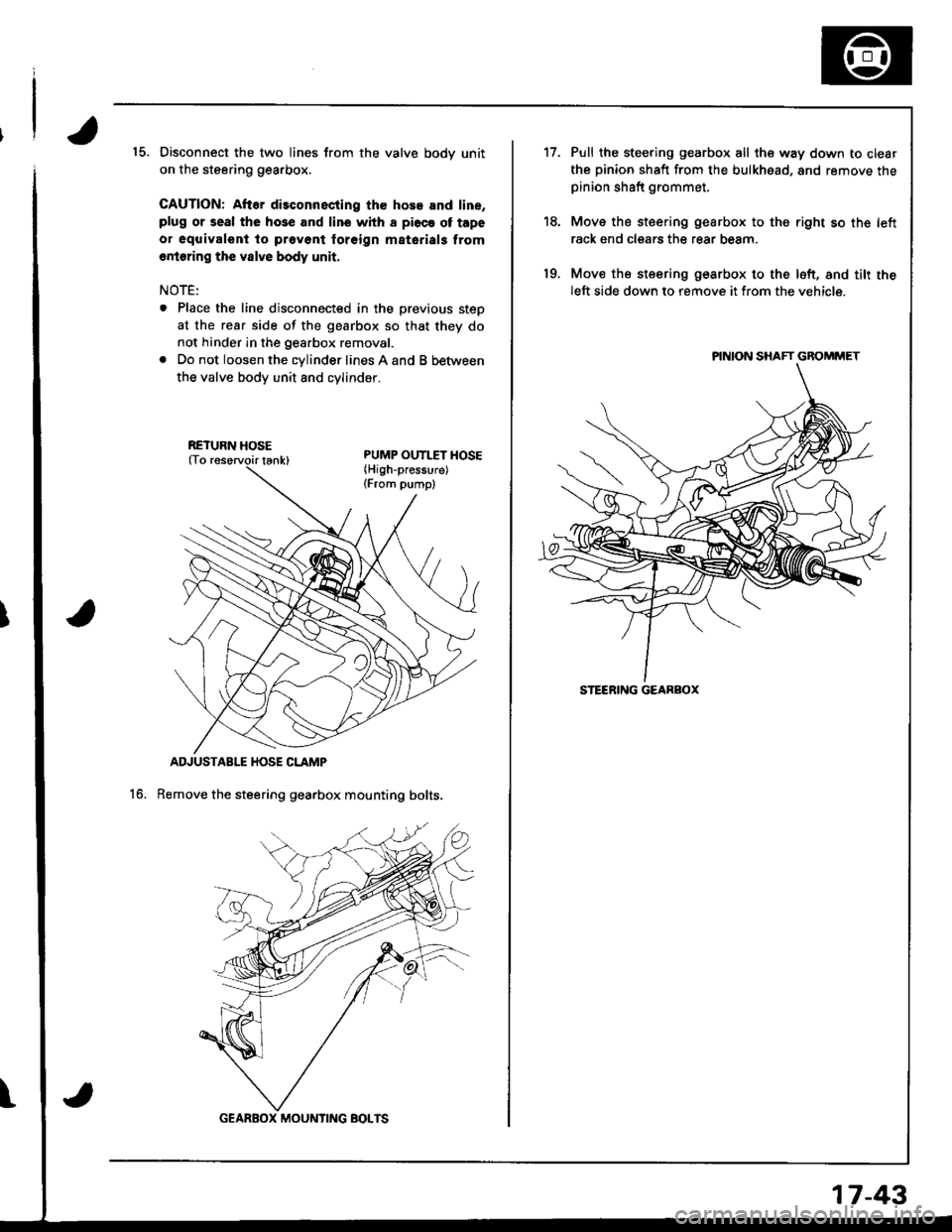
15. Disconnect the two lines from the valve bodv unit
on the steering gearbox.
CAUTION: After disconnscting the hose and line,plug or seal the hose and lino whh I pi6ce ot tape
o. oquivalent to prevont foreign matarials from
6rioring the vslve body unit,
NOTE:
. Place the line disconnected in the previous steD
at the rear side of the gearbox so that they do
not hinder in the gearbox removal.
. Do not loosen the cylinder lines A and B between
the valve body unit 8nd cvlinoer.
ADJUSTABLE HOSE CLAMP
Remove the steering gearbox mounting bolts.16.
\
RETURN HOSE
GEARBOX MOUNTING BOTTS
17-43
't7.
19.
Pull the steering gearbox all the way down to clear
the pinion shaft from the bulkhead, and remove thepinion shaft grommet.
Move the steering gearbox to the right so th€ left
rack end clears the rear beam.
Mov€ the steering gearbox to the loft, and tilt theleft side down to remove it from the vehicle.
PINION SHAFT GBOMMET
STEERING GEARBOX
Page 693 of 1681
Power Steering Gearbox
Disassembly
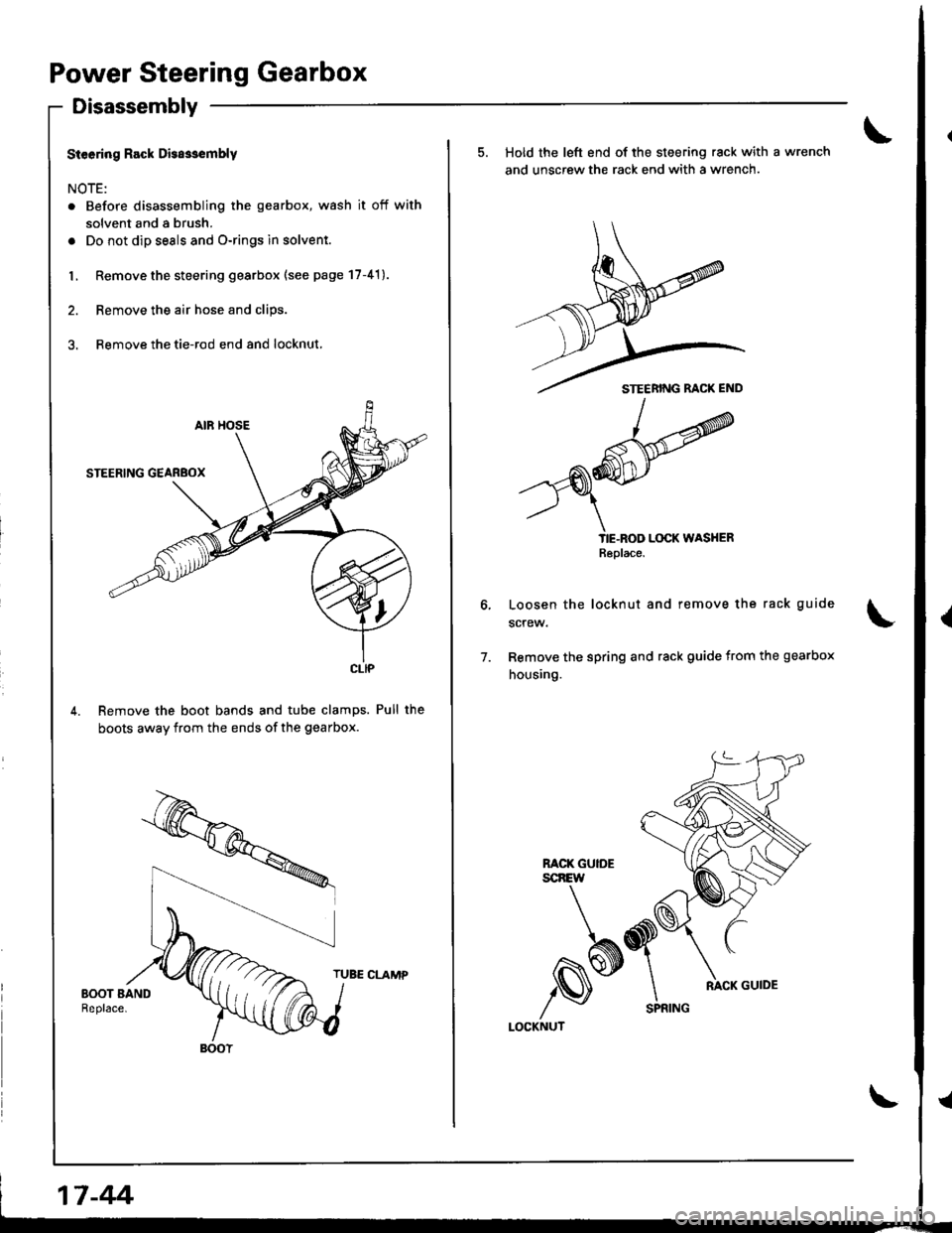
Steering Rack Disa3sembly
NOTE:
. Before disassembling the gearbox, wash it off with
solvent and a brush.
. Do not dip seals and O-rings in solvent.
L Remove the steering gearbox (see page 17-41).
2. Remove the air hose and clips.
3. Remove the tie-rod end and locknut,
Remove the boot bands and tube clamps. Pull the
boots away from the ends of the gearbox.
TUBE CLAMP
CLIP
BOOT
17-44
SPRING
5. Hold the left end of the steering rack with a wrench
and unscrew the rack end with a wrench.
TIE-ROD LOCK WASHERBePlace
Loosen the locknut and remove the rack guide
screw.
Remove the spring and rack guide from the gearbox
housing.
7.
RACK GUIDEscnEw
,s*LOCKNUT
RACK GUIDE
Page 694 of 1681
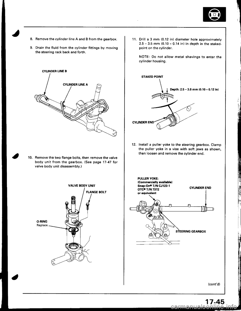
8.Remove the cylinder line A and B from the gearbox.
Drain the fluid from the cylinder fittings by moving
the steering rack back and forth.
Remove the two flange bolts, then remove the valve
body unit from the gearbox, (See page 17-47 for
valve body unit disassembly.)
FLANGE BOLT
10.
CYLINDER LINE B
VAI.VE BODY UNIT
11.Orill a 3 mm (0.12 in) diameter hole approximately
2.5 - 3.5 mm (0.10 - 0.14 in) in depth in the staked-point on the cylinder.
NOTE: Oo not allow metal shavings to enter the
cylinder housing.
12. Install a puller yoke to the steering gearbox. Clamp
the puller yoke in a vise with soft jaws as shown,
then loosen and remove the cvlinder end,
CYLINDER END
STAKED POINT
\\
i D.pth:2.5 - 3.0 mm {0.10 - 0.'12 inl
re
17-45l
Page 695 of 1681
Power Steering Gearbox
Disassembly (cont'dl
VINYL TAPE
12 mmFLANGE NUT
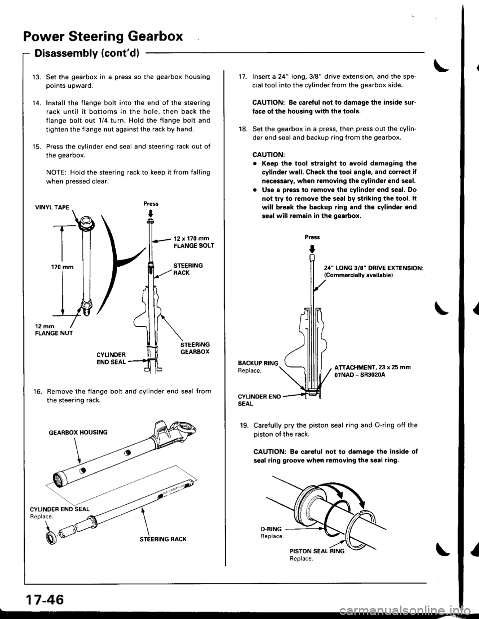
13. Set the gearbox in a press so the gearbox housing
pornts upward.
14. Install the flange bolt into the end of the steering
rack until it bottoms in the hole, then back the
flange bolt out 1/4 turn. Hold the flange bolt and
tighten the flange nut against the rack by hand.
15. Press the cylinder end seal and steering rack out of
the gearbox.
NOTE: Hold the steering rack to keep it from falling
when pressed clear.
T-
I
I170 mm
CYLINDEREND SEAL
Remove the flange bolt and cylinder end seal from
the steering rack.
Press
t
18.
17.
Ple3s
I
ATTACHMENT, 23 x 25 mm
07NAD - SR3020A
CYLINDER ENDSEAL
19. Carefully pry the piston seal ring and O-ring off the
oiston of the rack.
CAUTION: Be carelul not to damage the inside of
seal ring groove when remoying the seal ring.
lnsert a 24" long, 3/8" drive extensjon, and the spe-
cial tool into the cylinder from the gearbox side.
CAUTION: Be careful not to damage the inside sur-
lace of the housing with the lools.
Set the gearbox in a press, then press out the cylin-
der end seal and backup ring from the gearbox.
CAUTION:
. Keep the tool straight to avoid damaging the
cylinder wall, Chcck thc tool angle, and correct il
necessary, when removing the cylinder end s€al.
. Use a press to remove the cylinder end seal. Do
not try to remove the seal by striking the tool. lt
will brcak the backup ring and the cylinder end
seal will remain in the gesrbox.
Replace
17-46
Page 697 of 1681
Power Steering Gearbox
Disassembly (cont'd)
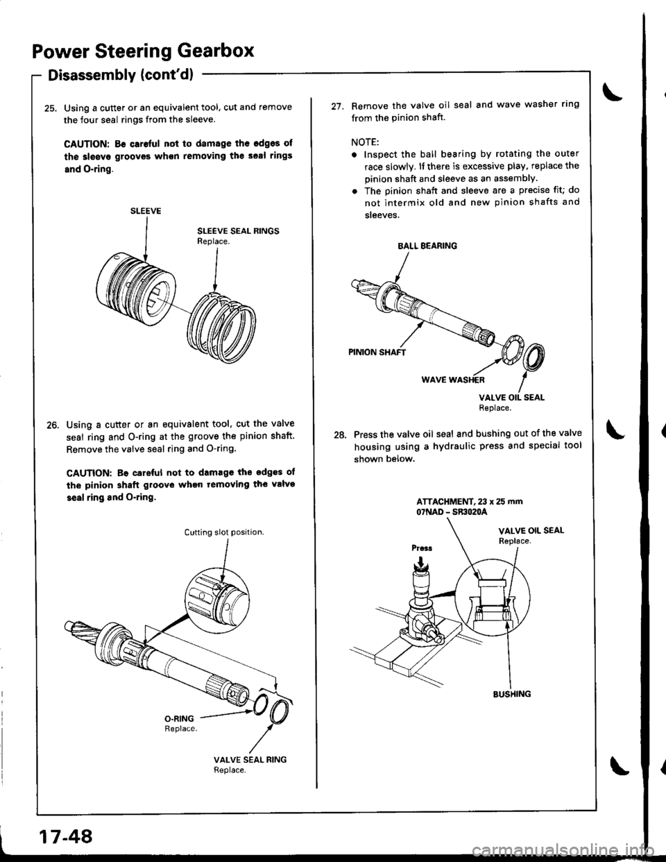
25. Using a cutter or an equivalent tool, cut and remove
the four seal rings from the sleeve.
CAUTION: 86 caroful not to damage the edgos of
the 3leeve grooves whon removing the scal rings
and O-ring.
Using I cutter or an equivalent tool, cut the valve
seal ring and O-ring at the groove the pinion shaft.
Remove the valve seal ring and O-ring.
CAUTION: 86 careful not to d.mago the sdges ol
lhe pinion shaft groove whgn removing the valvo
seal ring and O-ring.
SLEEVE
Cutting slot position.
17 -48
t"fRemove the valve oil seal and wave washer ring
from the pinion shaft.
NOTE:
. Inspect the ball besring by rotating the outer
race slowly. lf there is excessive play, replace the
pinion shaft and sleeve as an assembly.
. The pinion shaft and sleeve are a precise fit; do
not intermix old and new pinion shafts and
steeves.
VALVE OII- SEALReplace.
Press the valve oil seal and bushing out of the valve
housing using a hydraulic press and special tool
shown below.
ATTACHMENT, 23 x 25 mm
07NAD - SB3020A
VALVE OIL SEALReplace.
28.
BALL EEARING
BUSHING