glove box HONDA INTEGRA 1998 4.G User Guide
[x] Cancel search | Manufacturer: HONDA, Model Year: 1998, Model line: INTEGRA, Model: HONDA INTEGRA 1998 4.GPages: 1681, PDF Size: 54.22 MB
Page 1104 of 1681
.lI
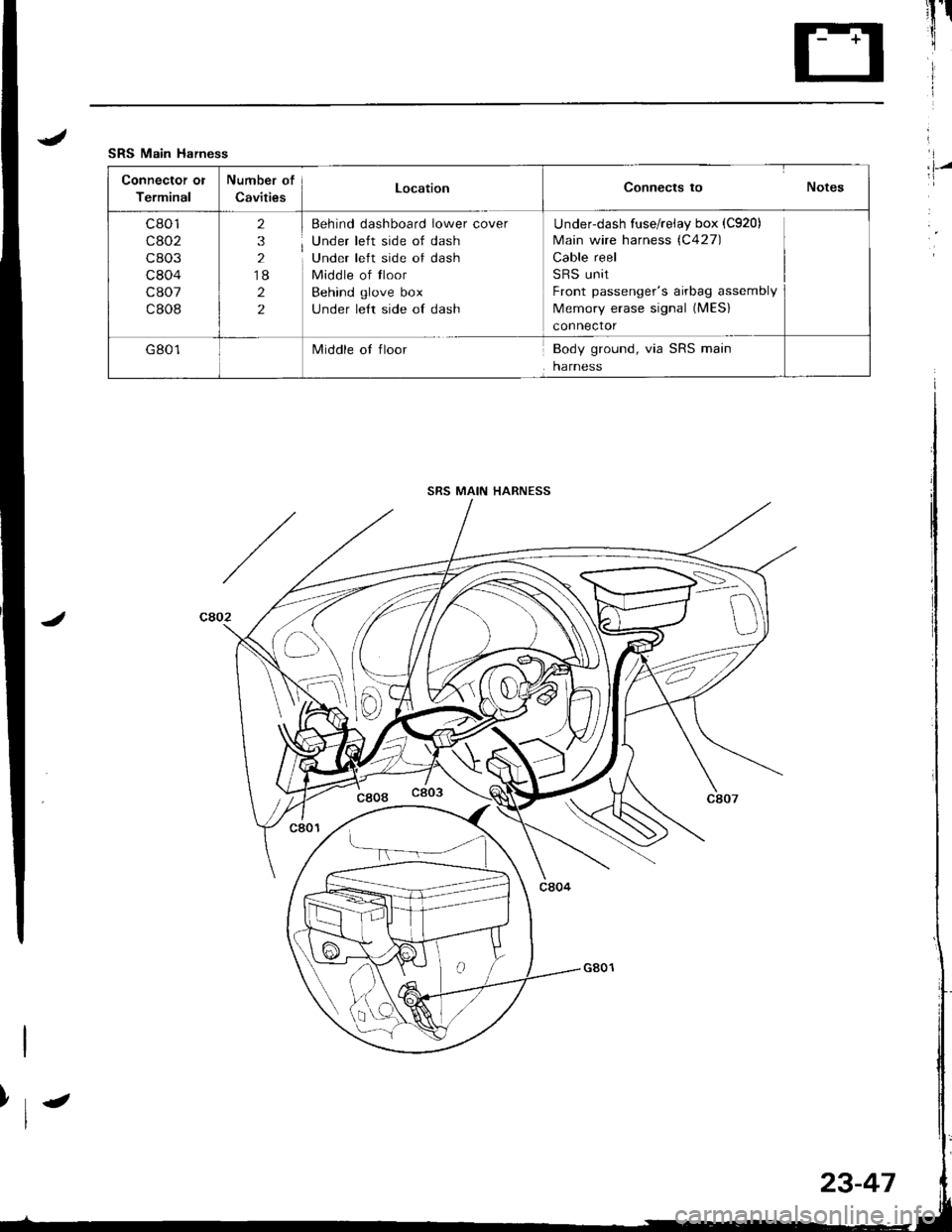
SRS Main Harness
Connector ol
Terminal
Number of
CavitiesLocationConnects to Notes
c801
cao2
c803
c804
c807
c808
2
3
2
18
2
2
Behind dashboard lower cover
Under left side of dash
Under left side of dash
Middle of tloor
Behind glove box
under le{t side of dash
Underdash fuse/reiay box (C920)
Main wire harness (C427)
Cable reel
SRS unit
Front passenger's airbag assembly
Memory erase signal (MES)
connector
G801Middle ot floorBody ground, via SRS main
harness
I,l-/
SRS MAIN HARNESS
>\-
D
23-47
Page 1117 of 1681
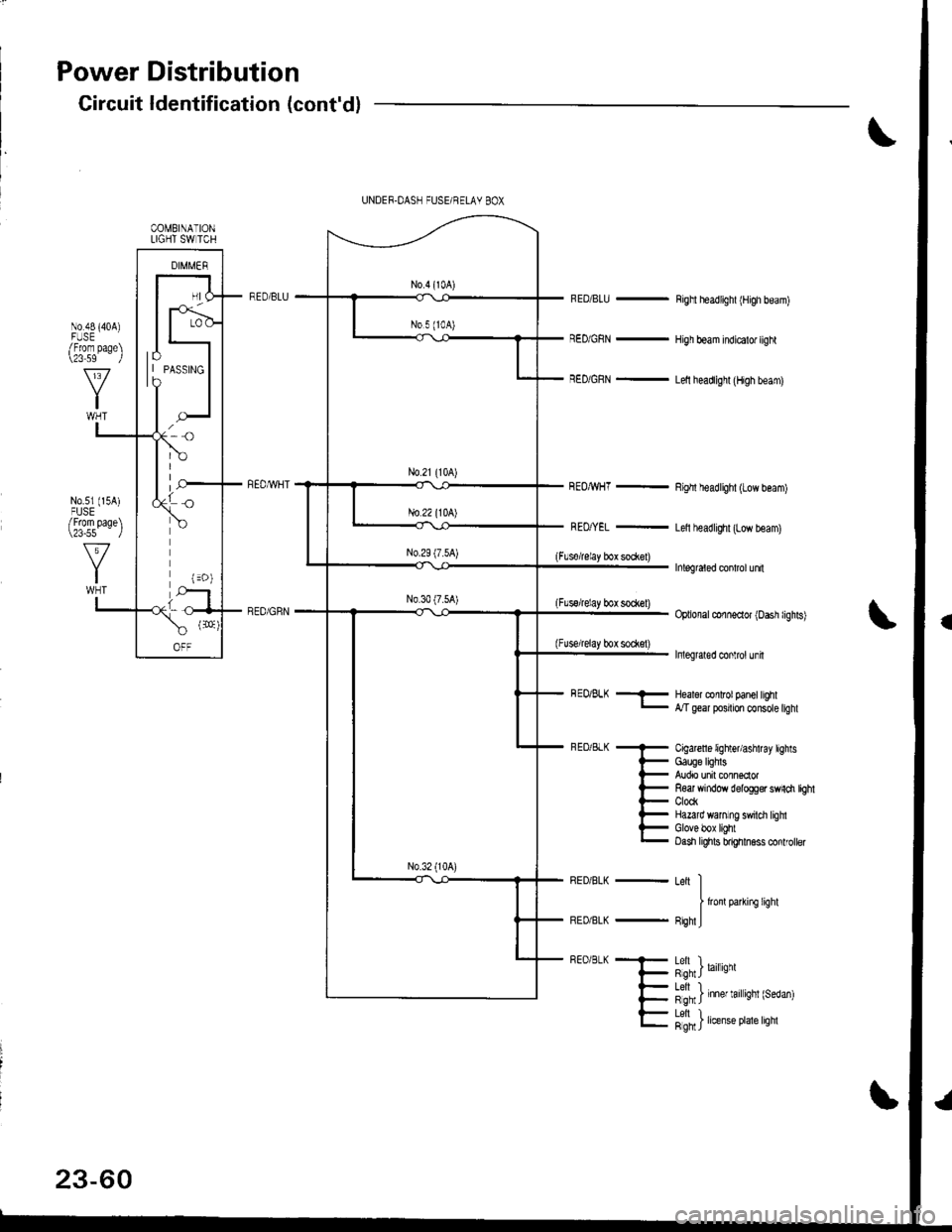
Power Distribution
Circuit ldentification (cont'd)
RED/BLU -
RED/GRN -
REOMHT -
Righl headlighl (High beam)
High beam indicalo. light
Lelt headlighl (High beam)
Righl headlighl (Low beam)
Letl headlighr (Low beam)
Inlegraled conlrol unn
Optional conneclor (Dash lighls)
Inleglaled conlrol unh
(Flsorelay box so*el)
(Flssrelay bot sock€l)
(Fuse/relay box sodet)
COMBINATIONLIGHT SW TCH
lo| | PAsslNGto
BEo/BLK -- Healor conlrol panel hghl- Mgear posrton consote tighl
Cigarcfl 6 lighter/ashtray lightsGauge lighlsAudio unit connsclorR€ar window delogg€r swnch tbhtClockHazard wanlng swilci lighlGlove box lightOash lights bnghhess conlroller
Leit II
I lronlparkifC lighl
FighlJ
h",J'n') '"",.*
l"fn' ) 'nn., '.', 'nnt {r"o"n)
23-60
Letl L.Rgh I rrense Prale lrgnl
Page 1121 of 1681
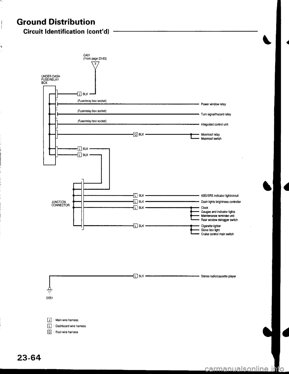
Ground Distribution
JUNCIIONCONNECTOR
U : Main wrre larness
E : oashboardwire haness
E , B*tr,it" h",n"..
Circuit ldentification (cont'dl
G40l(From page 23-63)
UNDEN.DASIFUSEi RELAYBOX
Turn sbnal/he2ad relay
hlegraled conlrol unil
BLh-Moonlmlleray- MooNool switch
BLK
BLK
8LK
ABS/SRS indicalor lighvci.dril
oash lighls brighhess clitroller
ClockGauges and indicalor lighlsMaiol€nan6 Gmind€a milR6ar window d6logger switch
A-^..'.''..'..- Cqal€nergrnet
l- Glove box lighlr- Ouise conlrol nan sw|ldr
Steleo mdio/cassello playel
G551
23-64
Page 1234 of 1681
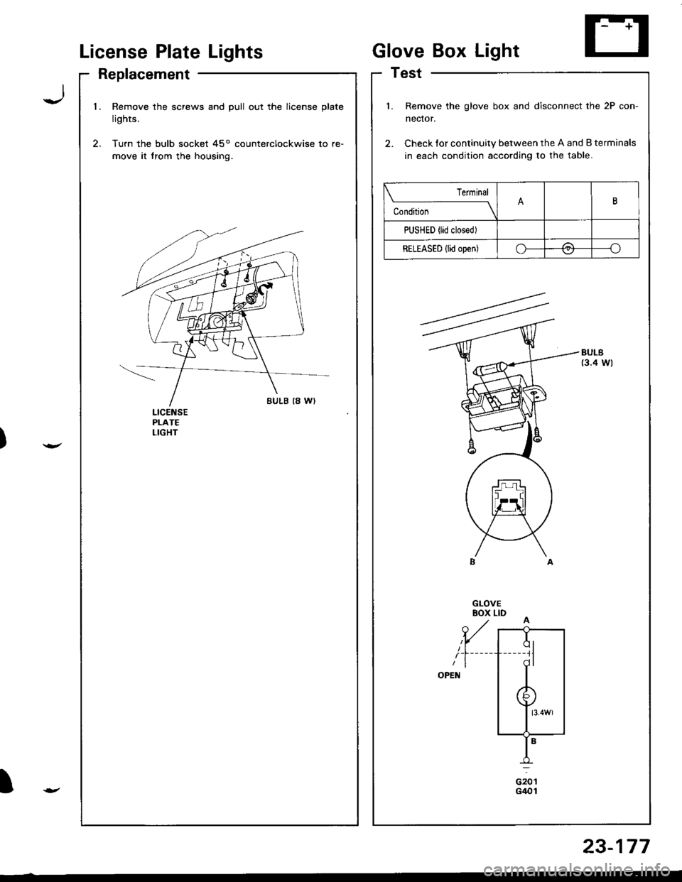
License PlateLights
Replacement
GloveBox Light
Test
Jl.Remove the screws and pull out the license plate
lights.
Turn the bulb socket 45o counterclockwise to re-
move it trom the housing.
l.
2.
Remove the glove box and disconnect the 2P con-
nector,
Check tor continuity between the A and B terminals
in each condition according to the table.
BULB(3.4 Wl
Terminal
c""il-------lB
PUSHED {lid closed)
RELEASED {lid open)o-/a---.ov
ciotG401t
23-177
Page 1266 of 1681
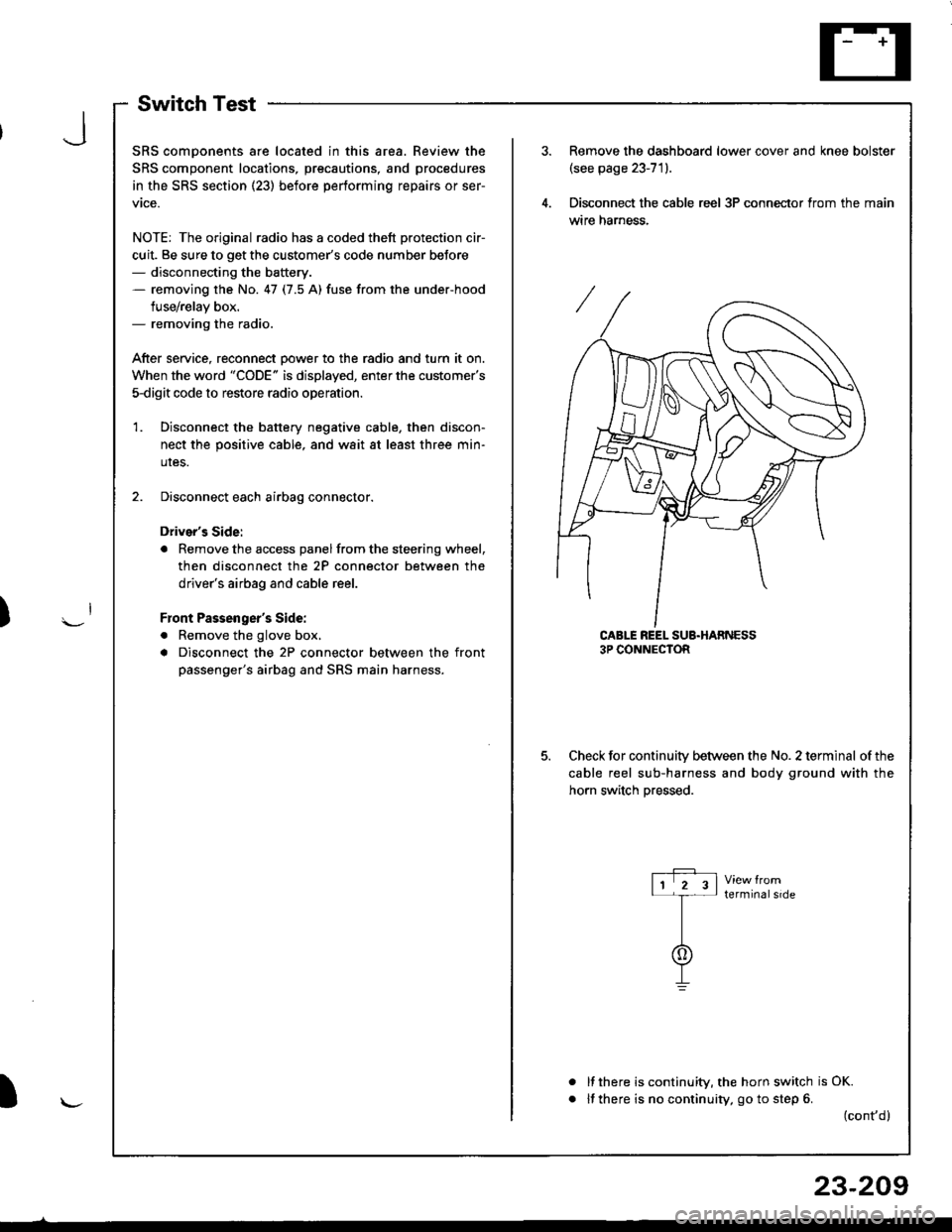
SwitchTest
SRS comDonents are located in this area. Review the
SRS component locations, precautions, and procedures
in the SRS section (23) before performing repairs or ser-
vtce.
NOTE: The original radio has a coded thett protection cir-
cuit. Be sure to get the customer's code number beJore- disconnecting the battery.- removing the No. 47 (7.5 A) fuse from the under-hood
fuse/relay box.- removing the radio.
After service, reconnect Dower to the radio and turn it on.
When the word "CODE" is displayed, enter the customer's
5-digit code to restore radio operation
Disconnect the battery negative cable, then discon-
nect the positive cable, and wait at least three min-
uIes.
Disconnect each airbag connector.
Driver's Side:
a Remove the access panel from the steering wheel,
then disconnect the 2P connector between the
driver's airbag and cable reel.
Front Passenger's Side:
. Remove the glove box,
a Disconnect the 2P connector between the front
passenger's airbag and SRS main harness.
1.
Remove the dashboard lower cover and knee bolster(see page 23-71).
Disconnect the cable reel 3P conneclor from the main
wtre narness.
CABLE REEL SUB.HARNESS3P CONNECTOR
Check for continuitv between the No. 2 terminal of the
cable reel sub-harness and body ground with the
horn switch Dressed.
terminalside
a
It there is continuity, the horn switch is OK.
lf there is no continuity, go to step 6. (cont,d)
r-P r11 2 3l-t-
I
I\-J
)
I
23-209
Page 1267 of 1681
Horn
Switch Test (cont'd)
Remove the driver's airbag assembly (refer to the
SRS sub-section in section 23).
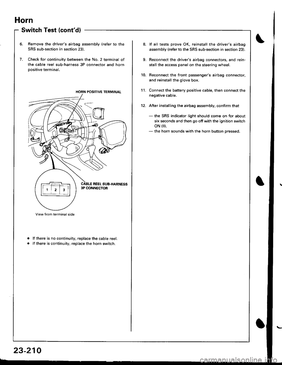
Check for continuity between the No. 2 terminal of
the cable reel sub-harness 3P connector and horn
Dositive terminal.
lf there is no continuity. replace the cable reel.
lf there is continuity, replace the horn switch.
a
a
HORN POSITIVE TERMINAL
23-210
9.
10.
11.
12.
lf all tests prove OK, reinstall the driver's airbag
assembly (re{er to the SRS sub-section in section 23).
Reconnect the driver's airbag connectors, and rein-
stall the access panel on the steering wheel.
Reconnect the front passenger's airbag connector,
and reinstall the glove box.
Connect the battery positive cable, then connect the
negative cable.
Atter installing the airbag assembly, confirm that
- the SRS indicator light should come on for about
six seconds and then go off with the ignition switch
oN 0t).- the horn sounds with the horn button pressed.
Page 1314 of 1681
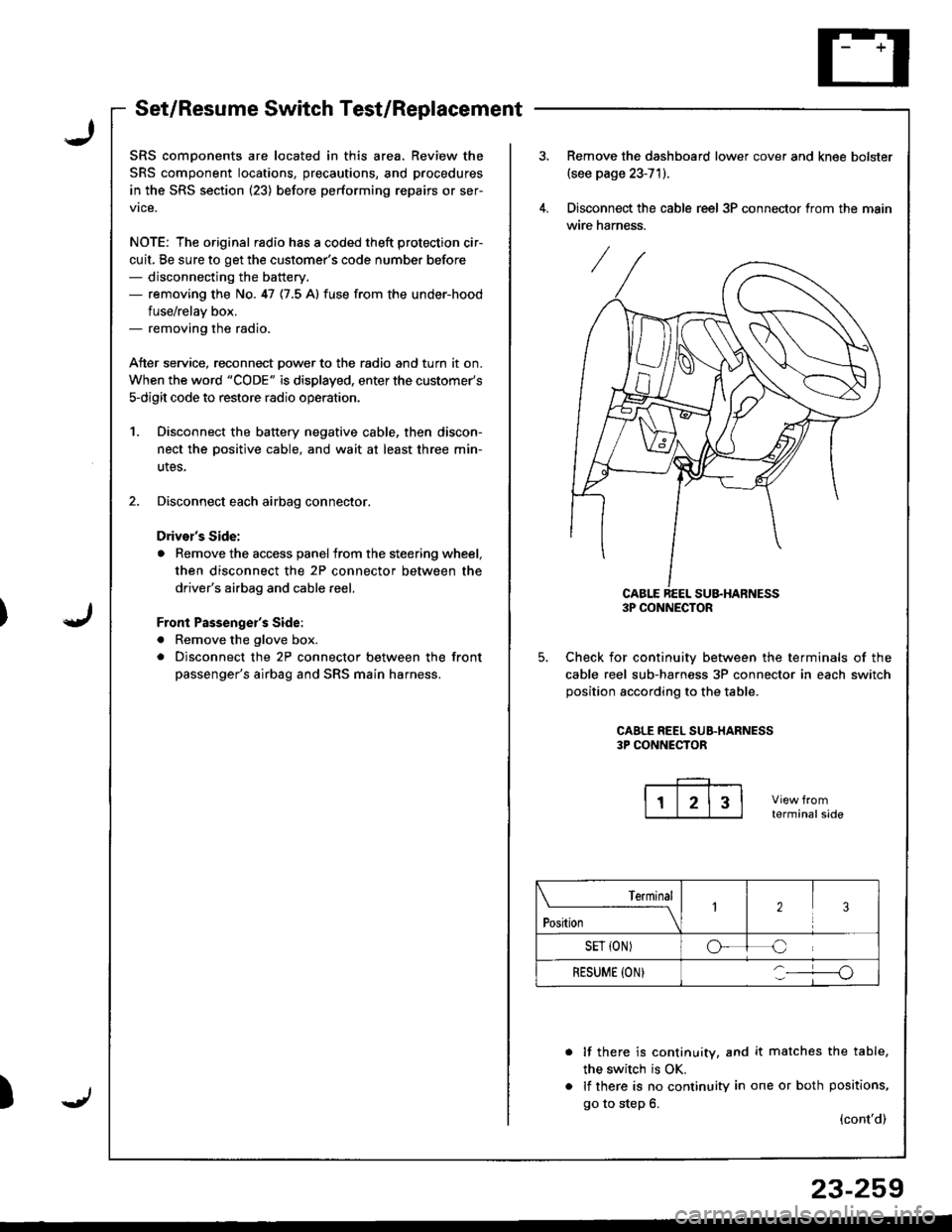
Set/Resume Switch Test/Replacement
SRS comDonents are located in this area. Review the
SRS component locations, precautions, and procedures
in the SRS section (23) before performing repairs or ser-
vice.
NOTE: The original radio has a coded theft protection cir-
cuit, Be sure to get the customer's code number before- disconnecting the battery.- removing the No. 47 {7.5 A} fuse from the under-hood
fuse/relav box.- removing the radio.
Atter service, reconnect Dower to the radio and turn it on.
When the word "CODE" is displayed, enter the customer's
s-digit code to restore radio operatior..
1. Disconnect the battery negative cable, then discon-
nect the oositive cable, and wait at least three min-
utes,
2. Disconnect each airbag connector.
Drivor's Side:
a Remove the access panel from the steering wheel,
then disconnect the 2P connector between the
driver's airbag and cable reel,
Front Passenge;'s Side:
a Remove the glove box.
. Disconnect the 2P connector between the front
passenger's airbag and SRS main harness.
)
Remove the dashboard lower cover and knee bolster(see page 23-71).
Disconnect the cable reel 3P connector trom the main
wire harness.
CABLE REEL SU&HARNESS3P CONNECTOR
Check for continuiw between the terminals of the
cable reel sub-harness 3P connector in each switch
position according to the table.
CAALE REEL SUB.HARNESS3P CONNECTOR
terminalside
lf there is continuity, and it matches the table,
the switch is OK.
lf there is no continuity in one or both positions,
go to step 6.(cont'd)
Terminal
t"*-
---\23
SET {ON)oC
RESUME (ON}o
23-259
Page 1315 of 1681
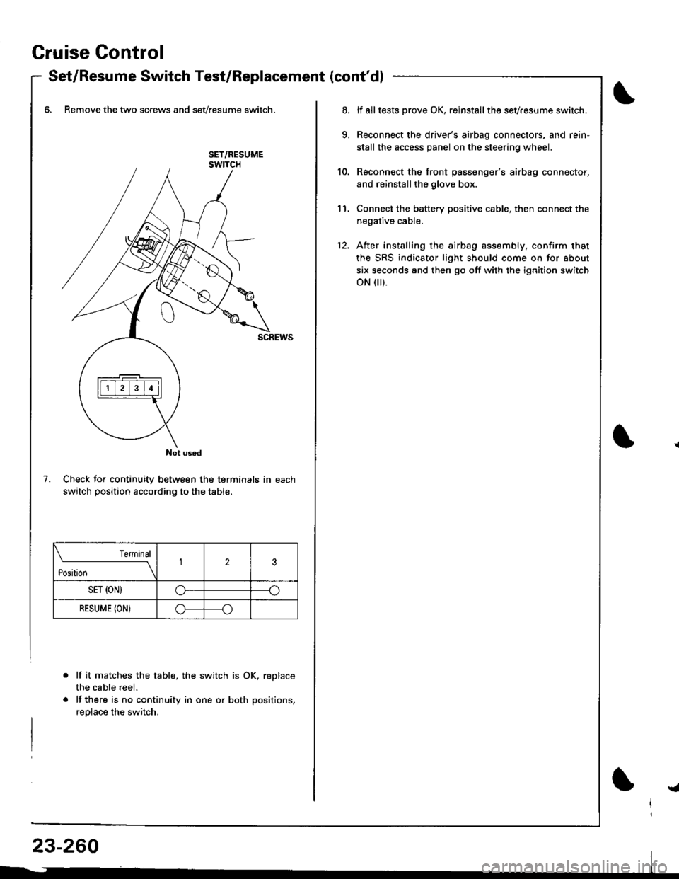
Gruise Control
- Set/Resume Switch Test/Replacement {cont'dl
6, Remove the two screws and sevresume switch.
Check for continuity between the terminals in each
switch position according to the table.
lf it matche$ the table, the switch is OK. replace
the cable reel.
lf there is no continuity in one or both positions,
reolace the switch.
Not used
7.
Terminal
t*n*------l23
SET {ON)G----o
RESUME (ON}o----o
lf alltests prove OK, reinstallthe sevresume switch.
Reconnect the driver's airbag connectors, and rein'
stall the access panel on the steering wheel.
Reconnect the front passenger's airbag connector,
and reinstallthe glove box.
Connect the battery positive cable, then connect the
negative cable.
After installing the airbag assembly, confirm that
the SRS indicator light should come on for about
six seconds and then go off with the ignition switch
oN flr).
11.
12.
!a
Page 1339 of 1681
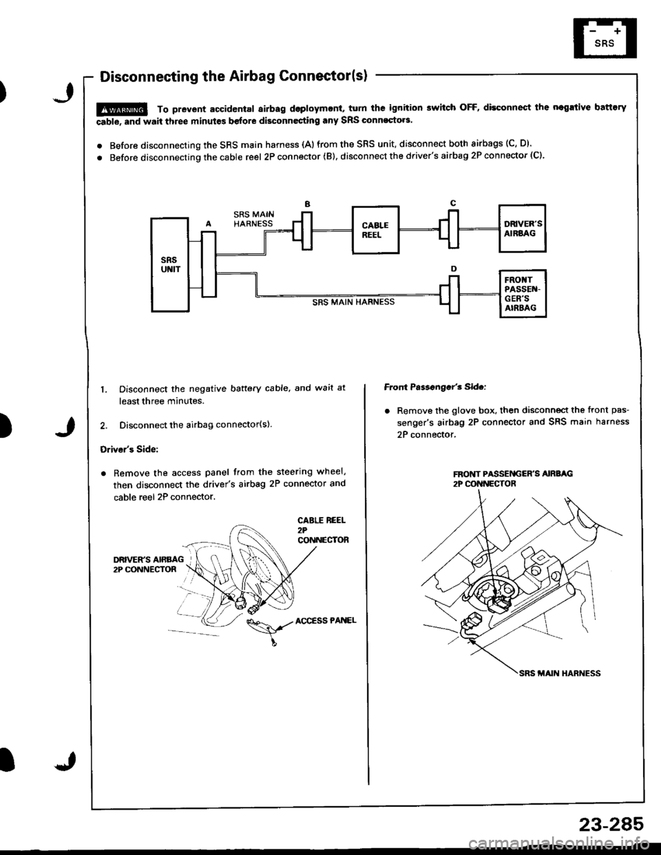
Disconnecting the Airbag Connector(s)
!@ To prevent accidental airbag dsploymcnt, turn ths ignition switch OFF, disconnect the negrtive battory
able, and wait three minut€s before disconnesting any SRS Glnnoqto.s.
. Before disconnecting the SRS main harness {A)from the SRS unit, disconnect both airbags (C, D).
. Before disconnecting the cable reel 2P con nector ( B). disconnect the driver's airbag 2P connector (C).
)
1. Disconnect the negative baftery cable. and wait at
least three minutes.
2. Disconnect the airbag connector(s).
Driver's Side:
. Remove the access panel from the steering wheel,
then disconnect the driver's airbag 2P connector and
cable reel 2P connector.
CABLE REEL2?CONNECTOR
Front Ps$sngar'3 Sid.:
. Remove the glove box. then disconnect the front pas-
senger's airbag 2P connector and SRS main harness
2P connector,
\,./AccEssPANEL
23-2A5
Page 1371 of 1681
)
Airbag
Replacement
After a collision in which the airbags were deployed, the
airbag assemblies and the SRS unit must be replaced'
!!@ stole a removed sirbag with the pad sur'
ii6--up. tt tle sirbag i5 impropetly stored lace down,
accidental doploym€nt Gould propol tho unit with
enough lorce to cause serious iniury.
CAUTION:
. Do not install usad SRS parts from another vehicle'
When repairing, u3e only new SRS parB.
. Carefully inspsct the airbag befor€ you iGtall it Do
not install 8n airbag that shows signs of being
dlopped or improperly handled' such a3 dsnts,
cracks or defolmalion
. Always disconnact lhe airbag conneqtor{s) when the
harn$s is disconn€ctsd.
. Do not dislsembla or tlmp€r with thr sirbag
1. Make sure vou have th€ anti-theft code for the radro,
then write down the frequencies for the radio's pre-
set buttons.
2. Disconnect the battery negative cable, then discon-
nect the positive cable from the battery, and wait at
least three minutes.
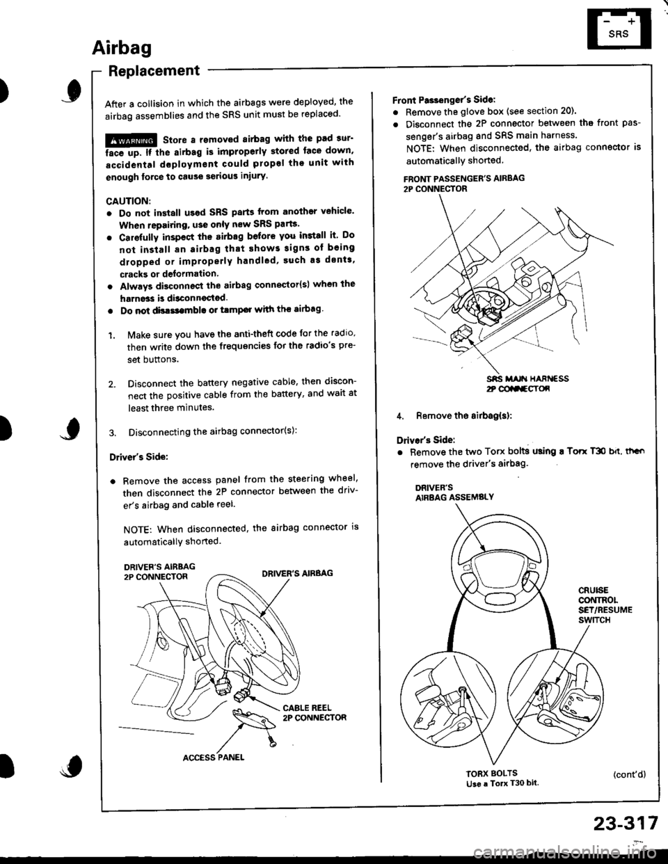
3. Disconnecting the airbag connector(s):
Driver's Side:
a Remove the access panel from the steering wheel,
then disconnect the 2P connector between the driv-
er's airbag and cable reel.
NOTE: When disconnected, the airbag connector is
automaticallY shorted.
)
23-317
2t @aa-gY(x
Front Pa3ienget's Sidel
. Remove the glove box (see section 20).
. Disconnect the 2P connector betwsen tha front pas-
senger's airbag and SRS main harness.
NOTE: When disconnected, the airbag conngctor is
automaticallY shoned
FBONT PASSENGER'S AIRBAG2P CONNECTOR
4. Remove the airbag(s):
Drivar's Side:
. Bemove the two Torx bolts using ! Torr T3O b{t, thGo
remove the driver's airbag'
DRIVER'SAIRBAG ASSEMBLY
CRUISECONINOLSET/RESUMEswtTcH
TORX BOLTSti3e a To T30 bit.(cont'd)