glove box HONDA INTEGRA 1998 4.G Owner's Manual
[x] Cancel search | Manufacturer: HONDA, Model Year: 1998, Model line: INTEGRA, Model: HONDA INTEGRA 1998 4.GPages: 1681, PDF Size: 54.22 MB
Page 1373 of 1681
I
I
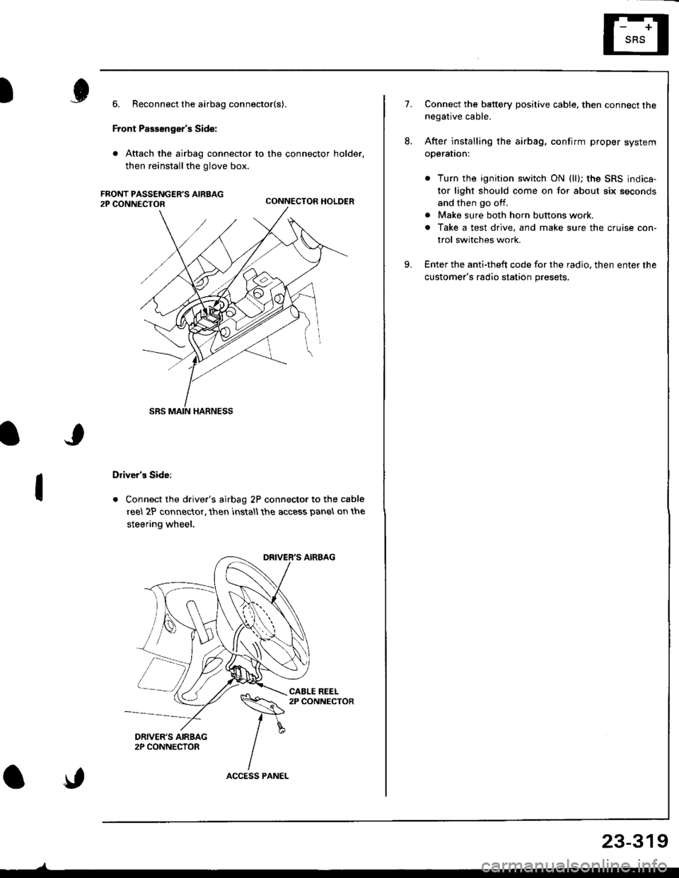
6. Reconnect the airbag connector(s).
Front Passenger's Side:
. Attach the airbag connector to the connector holder.
then reinstallthe glove box.
CONNECTOR HOLDER
Driver's Side:
. Connect the driver's airbag 2P connector to the cable
reel 2P connector, then rnstall the access panel on the
steering wheel.
\,
23-319
7.Connect the baftery positive cable, then connect thenegative cable.
After installing the airbag, confirm proper system
operal|on:
. Turn the ignition switch ON (ll); the SRS indica-
tor light should come on for about six seconds
and then go off.
. Make sure both horn buttons work.
. Take a test drive, and make sure the cruise con-
trol switches work.
Enter the anti-theft code for the radio. then enter the
customer's radio station presets,
9.
Page 1374 of 1681
Before scrapping any airbags (including those in a whole
car ro be scrappedl, the airbags must be deployed. lf the
car is still within the warranty period, before you deploy
the airbags, the Acura District Technical Manager mustgive approval and/or special instructions. Only after theairbags have been deployed (as the result of vehicle colli-
sion, for example). can they be scrapped.
lf the airbags appear intact (not deployed). treat themwith extreme caution.
Follow this procedure:
Deploying the Airbags: In"vehicle
NOTE: lf an SRS vehicle is to be entirely scrapped. itsairbags should be deployed while still in the vehicle. Theairbags should not be considered as salvageable parts
and should never be installed in another vehicle.
E@ Contirm that each airbsg is securelymounted; otherwise, severe personal iniury could resultfrom deployment.
1. Disconnect the battery negative cable, then discon-nect the positive cable.
2. Confirm that the special tool is functioning properly
by following the check procedure on the label onthe tool or on page 23-321.
Driver's Airbag:
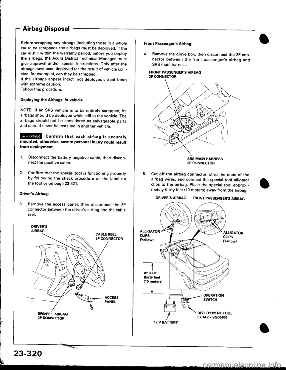
3. Remove the access panel, then disconnect the 2pconnector between the driver's airbag and the cablereel.
DRIVEE'SAIRBAGCABLE REEL2P CONNECTOR
Airbag Disposal
Oit,ER S AIREAG2P OdIIIECTOR
\\+- AccEss
I
PANEL
12 V EATTERY
Front Passenger's Airbag:
4. Remove the glove box, then disconnect the 2p con-nector between the front passenger's airbag andSRS main harness.
FRONT PASSENGER'S AIRBAG2P CONN€CTOR
SRS MAIN HARNESS2P CONNECTOR
5. Cut off the airbag connector, strip the ends ot theairbag wires. and connect the special tool alligatorclips to the airbag. Place the special tool approxi-mately thirty feet (10 meters) away from the airbag.
DRIVER'S AIRBAG FRONT PASSENGER'S AIRBAG
ALLIGATORCLIPSlYellowl
ALLIGATORCLIPSlYellowl
-T--
IAt leastthiny tcet110 meters)
IV
23-320
Page 1375 of 1681
)6.
7.
8.
Connect a 12 volt battery to the tool:
. lf the green light on the tool comes on, the alr-
bag igniter circuit is defective and cannot deploy
the airbag. Go to Damaged Airbag Specia I
Procedure.
. lfthe red light on the tool comes on, the airbag is
ready to be deployed.
Push the tool's deployment switch The airbag
should deploy (deployment is both highly audible
and visible; a loud noise and rapid inflation of the
bag, followed by slow deflation).
. lf the airbags deploy and the green light on the
tool comes on, continue with this procedure
. lf an airbag doesn't deploy. yet the green light
comes ON, its igniter is defective. Go to Dam-
aged Airbag Special Procedure.
!!@ During deployment, the airbag c8n
become hot enough to burn you Wait thirtY min-
ut€s after d€ployment befote touching the assem-
blv.
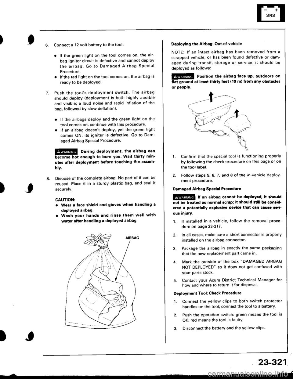
Dispose of the complete airbag. No part of it can be
reused. Place it in a sturdy plastic bag, and seal it
securery.
CAUTION:
. wear a lace shield and gloves when handling a
deployed airbag.
. Wash your hands and rinse them well with
water after handling a deployed sirbag
)
Deploying the Airbag: Out-ot-vehicle
NOTE: lf an intact airbag has been removed from a
scraDDed vehicle, or has been found defective or dam-
aged during transit, storage or service, it should be
deoloved as follows:
@@ Position th€ airbag laca up. outdoors on
tlat ground at l€ast thirty leet (10 m) ftom any obstacles
or people.
1. Confirm that the special tool is functioning properly
by tollowing the check procedure on thls page or on
the tool lab€|.
2. Follow steps 5, 6, 7, and 8 ol the in.vehicle deploy'
ment orocedure.
Damaged Airbag Sp€citl Procedurc
!@ [ an airbag cannot be d.ploytd, h 3hoold
not be lreated as normal scrap; it should 3till b. corlrkl
ered a polentially sxplosive device that can clura tari
ous iniury.
1. lf installed in a vehicle, follow the removal proce-
dure on page 23-317.
2. ln all cases, make sure a short connector is properly
installed on the airbag connector.
3. Package the airbag in exactly the same packaging
that the new replacement part came In.
4. Mark the outside of the box "DAMAGED AIRBAG
NOT DEPLOYED" so it does not get confused with
your Parts stock.
5. Contact your Acura District Technical lvanager for
how and where to return it for disposal.
Deployment Tool: Ch€ck Ptocedure
1. Connect the yellow clips to both switch protector
handles on the tool; connect the tool to a battery
2. Push the operation switch: green means the tool is
OK; red means the tool is faultv.
3. Disconnect the battery and the yellow clips
23-321
Page 1383 of 1681
).1
Contents
How to Use This l\.4anual 1Circuit Schematics (see Circuit Index)Fuse/Relaylnformation 6ComponentLocation Photographs 201
Connector Cavity Numbers 202Connectorldentification 203
Ground-to-Components Index 6-6Wire Harness Routing 203Circuit ldentification lor ln-Line and Fuse Box Connectors
Circuit Index
Air conditionerAir delivery 61Blower controls 60Compressor controls 62Fans 63Anti-lock brake system (ABS) 44A/T gear position indicator 89Automatic transmission controls'98199 models 39'00 models 39-4Back-up lightsHatchback 110Sedan 110- 1Brake system indicator light
USA 71Canada 71-1Brake lightsHatchback 110-6Sedan 110-7Cargo area light (Hatchback) 114-3Ceiling light 114-2Charging system 22Cigarette lighter 155
Clock 154Condenser fan 63Console lights 114Cruise control 34Dash lights 1 14Daytime running lights 110-8Door open indicator 114-2Engine coolant temperature gauge 81Engine oil pressure indicator light 72Fog lights 110-14Front parking lights 110-11Front side marker lights 110-11Fuel gauge 81Fuse/relay boxUnder-dash 6Under-hood 6-3Under-hood ABS 6-5Gauges 81Glove box light 114Ground distribution 14Ground-to-Componentsindex 6-6Hatch open indicator '114-3
Hatch opener '134
Hazard warning lightsHatchback 'l l0-2Sedan 110-4Headlights 1'10-8Headlight switch 100HeaterAir delivery 61Blower controls 60Fanswith A,/C 63without A,/C 63-2Horns 40lgnilion key reminder 73lgnition system 20
204
lmmobilizer system ('00 model) 132lndicators 80Integrated control unit 70Interlock system'98199 models 138'00 models 138-1License plate lightsHatchback 110-12Sedan 110-13Lights-on reminder 73Low fuel indicator light 74l\,4aintenance reminder light 83l\iloonroof 122Odometer 81-1Power antenna 151Power distributionBattery to ignilion switch, fuses, and relays
Fuses to relays and components 10-2Power door locksHatchback '130
Sedan 130-2Power mirrorsHatchback 141Sedan 141-1Power windowsHatchback 120Sedan 120-2Programmed fuel injection system (PGM-Fl)'98199 models 23'00 models 24Radiator fanwith tuC 63without A,/C 63-2Rear parking lightsHatchback 110-12Sedan 110- 13Rear window defogger 64Seat belt reminder 73Security system 133Speedometer Il-1Spotlights 114-2Starting syslemAutomalictransmission 21l\.4anualtransmission 21-1Stereo sound system 150Supplemental restraint system (SRS) 47Tachometer 81- 1TaillightsHatchback 110-12Sedan 110-13Trailer lighting conneclor 118Trunk lid open indicator 114-3Trunk light (Sedan) 114-3Turn signal lightsHatchback 110-2Sedan 110-4Vehicle speed sensor (VSS) 33Wiper/washerFront 91Rear 92
10
).1
I
Xr
12Fg oAmerican Honda Motor Co., Inc. - All Rights Reserved Service Communications 275 pages
Page 1406 of 1681
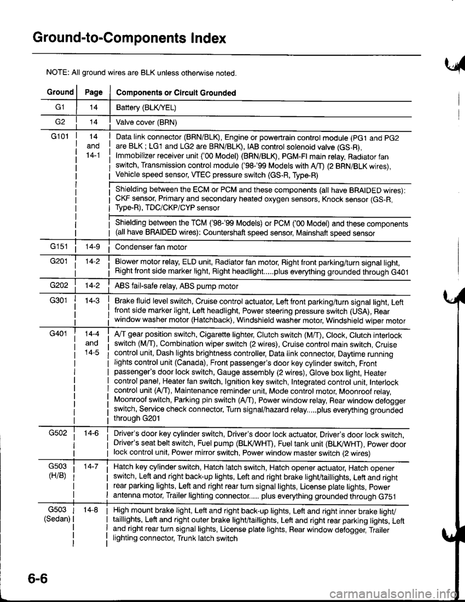
Ground-to-Components I ndex
NOTE: All ground wires are BLK unless otherwise noted.
GroundPageComponents or Circuit Grounded
Battery (BLIVYEL)
--t'I Valve cover (BRN)
G101t.+
and
14-1
Daia link connector (BRN/BLK), Engine or powertrain controt module (pct and pG2
are BLK; LG1 and LG2 are BRN/BLR, IAB controt solenoid valve (GS-B),
lmmobilizer receiver unit ('00 Model) (BRN/BLR, PGM-Ft main retay, Radiator fan
switch, Transmission control module ('98.�99 Models with MD (2 BRN/BLK wires),
Vehicle speed sensor, WEC pressure switch (GS-R, Type-R)
Shielding between the ECM or PCM and these components (all have BRAIDED wires):
CKF sensor, Primary and secondary heated oxygen sensors, Knock sensor (GS-R,
Type-R), TDC/CKP/CYP sensor
Shielding between the TCM ('98-'99 Models) or PCM ('00 Model) and these components(all have BRAIDED wires): Countershaft speed sensor, Mainshaft speed sensor
G1s1 ii Condenser fan motor
Brake fluid level switch, Cruise control actuator, Left front parking/turn signal light, Left
front side marker light, Left headlight, Power steering pressure switch (USA), Rear
window washer motor (Hatchback), Windshield washer motor, Windshield wiper motor
14-3
Blower motor relay, ELD unit, Badiator fan motor, Right front parking/turn signal light,
Right front side marker light, Right headlight.....plus everything grounded through G401
ABS fail-safe relay, ABS pump motor
G40114-4
ano
l4-c
A,/T gear position switch, Cigarette lighter, Clutch switch (M,/T), Ctock, Ctutch interlock
switch (MfD, Combination wiper switch (2 wires), Cruise control main switch, Cruise
control unit, Dash lights brightness controller, Data link connector, Daytime running
lights control unit (Canada), Front passenger's door key cylinder switch, Frontpassenger's door lock switch, Gauge assembly (2 wires), Glove box light, Heater
control panel, Heater tan switch, lgnition key switch, Integrated control unit, Interlock
control unit (AfI), Maintenance reminder unit, Mode control motor, Moonroof relay,
Moonroof switch, Parking pin switch (AfD, Power window relay, Rear window defogger
switch, Service check connector, Turn signal/hazard relay.....plus everything grounded
throuoh G201
Driver's door key cylinder switch, Driver's door lock actuator, Drivels door lock switch,Driver's seat belt switch, Fuel pump (BLI(/WHT), Fuel tank unit (BLI(/WHT), power doorlock control unit, Power mirror switch, Power window master switch (2 wires)
Hatch key cylinder switch, Hatch latch switch, Hatch opener actuator, Hatch ooener
switch, Left and right back-up lights, Left and right brake light/taillights, Lett and right
rear parking lights, Left and right rear turn signal lights, License plate lights, power
antenna motor, Trailer lighting connector..... plus everything grounded through G751
6-6
'14-8G503
(Sedan)
High mount brake light, Left and right back-up lights, Lett and right inner brake tighv
taillights, Left and right outer brake light/taittights, Left and right rear parking tights, Leftand right rear turn signal lights, License plate lights, Rear window detogger, Trailer
lighting connector, Trunk latch switch
Page 1424 of 1681
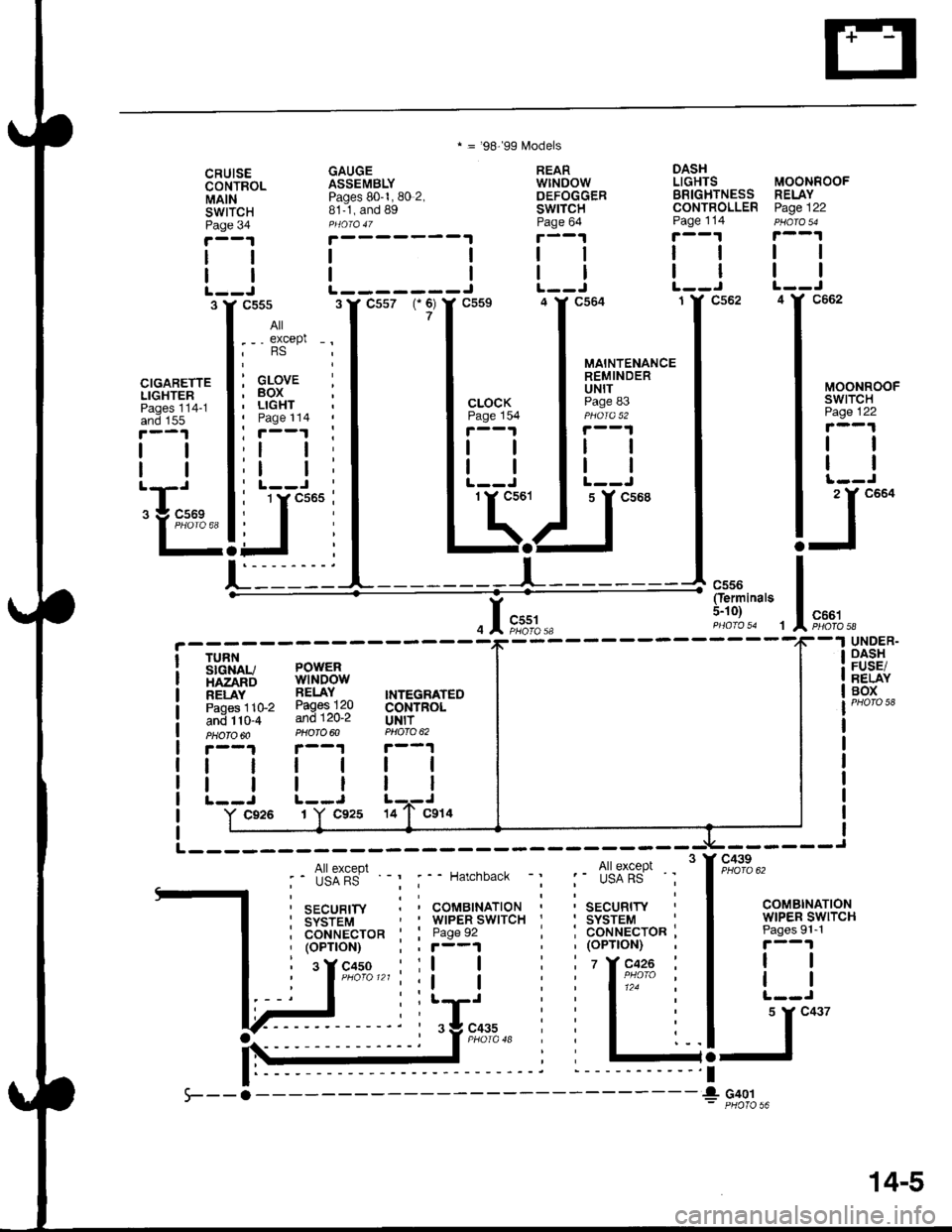
* = '98-'99 f,4odels
CRUISECONTROLMAINswrTcHPage 34
GAUGEASSEMBLYPages 80-1, 80 2,81-1, and Bg
REARwtNDowDEFOGGERSWITCHPage 64
DASHLIGHTS
Page 114
BRIGHTNESS RELAYCONTROLLER Page 122
MOONROOF
I
IJc662L-------J
CIGARETTELIGHTERPages 114-1and 155
tl
All
. - - except -.,RS
: GLOVE ;, BOX' LIGHTI Page 114
'll
:l t:
MOONROOFswtTcHPage 122
tl
ll
2 Y C664
I
:F.
Oerminals5-10)c661PHOfA 58
TURNSIGiIAU POWERHAZARD WINDOWRELAY RELAY INTEGRATEDpaoes 11G2 Pages 120 CONTROLani tt0-+ and120-2 UN|T?HOTO'O PHOTO@ PNO|O 62
r-.1r--1|.--1
c45o :ll
------Jc439
COMBINATIONWIPER SWITCHPages 9l-'l
r--1
tl
llL-.J
5 Y C437
-l
UNDER-OASIIFUSE/BELAYBOX
tl
tl
tl
ll
c926 1Y C92s 14
I coHuecron ' : Page 92, (oPTtoN),(oPnoN);,r--1
i sYcrso lll I
G401
14-5
Page 1578 of 1681

67. Below Center of Dash, Left of Heater Unit70. Below Right Side of Front Console
68. Behind Front Console Panel71. Below Bear Console
69. Behind Center ot Dash72. Below Glove Box
201-11
Page 1579 of 1681

Component Location
.l
73. Behind Glove Box76. Above Right Kick Panel
74. Behind Right Side Glove Box77. Behind Right Kick Panel ('98-'99 Modets)
75. Below Right Side of Dash
201-12
78. Behind Right Kick Panet (ECM or pCM Removed)
\
Page 1591 of 1681

Gomponent Location
145. Behind Glove Box
201-24
Page 1614 of 1681
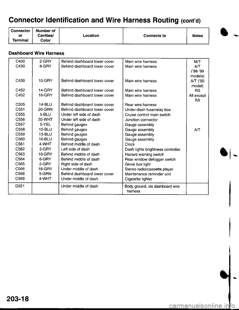
Connector ldentification and Wire Harness Routing (conrd)
Connector
or
Terminal
Number of
Cavities/
Color
LocationConnects toNotes
Dashboard Wire Harness
c430
c430
c430
c452
c452
UCUC
lJcc I
uccc
trCSO
c557
c558
uccv
c560
c561
c562
UCOJ
uco4
UJb5
ucoo
ucoo
UCOY
2-GRY
8-GRY
1O.GRY
14-GRY
16.GRY
14.BLU
2O.GRN
5-BLU
2O-WHT
5-YEL
1O.BLU
13-BLU
16-8LU
4.WHT
3-GRY
1O-GRY
6-GRY
2-GRY
16.GBY
5-GRN
4-WHT
Behind dashboard lower cover
Behind dashboard lower cover
Behind dashboard lower cover
Behind dashboard lower cover
Behind dashboard lower cover
Behind dashboard lower cover
Behind dashboard lower cover
Under left side of dash
Under left side of dash
Behind gauges
Behind gauges
Behind gauges
Behind gauges
Behind middle ot dash
Left side ol dash
Behind middle of dash
Behind middle of dash
Right side of dash
Under middle of dash
Behind dashboard lower cover
Under middle of dash
Main wire harness
Main wire harness
Maih wire harness
Main wire harness
Main wire harness
Rear wire harness
Under-dash fuse/relay box
Cruise control main switch
Junction connector
Gauge assembly
Gauge assembly
Gauge assembly
Gauge assembly
Clock
Dash lights brightness controller
Hazard warning switch
Rear window defogger switch
Glove box light
Stereo radio/cassette player
Maintenance reminder unit
Cigarette lighter
M/T
Arl
/'oR-'oo
models)
A/T (00
model)
RS
All except
RS
Aft
G551Under middle of dashBody ground, via dashboard wire
namess