oil HONDA INTEGRA 1998 4.G Workshop Manual
[x] Cancel search | Manufacturer: HONDA, Model Year: 1998, Model line: INTEGRA, Model: HONDA INTEGRA 1998 4.GPages: 1681, PDF Size: 54.22 MB
Page 36 of 1681
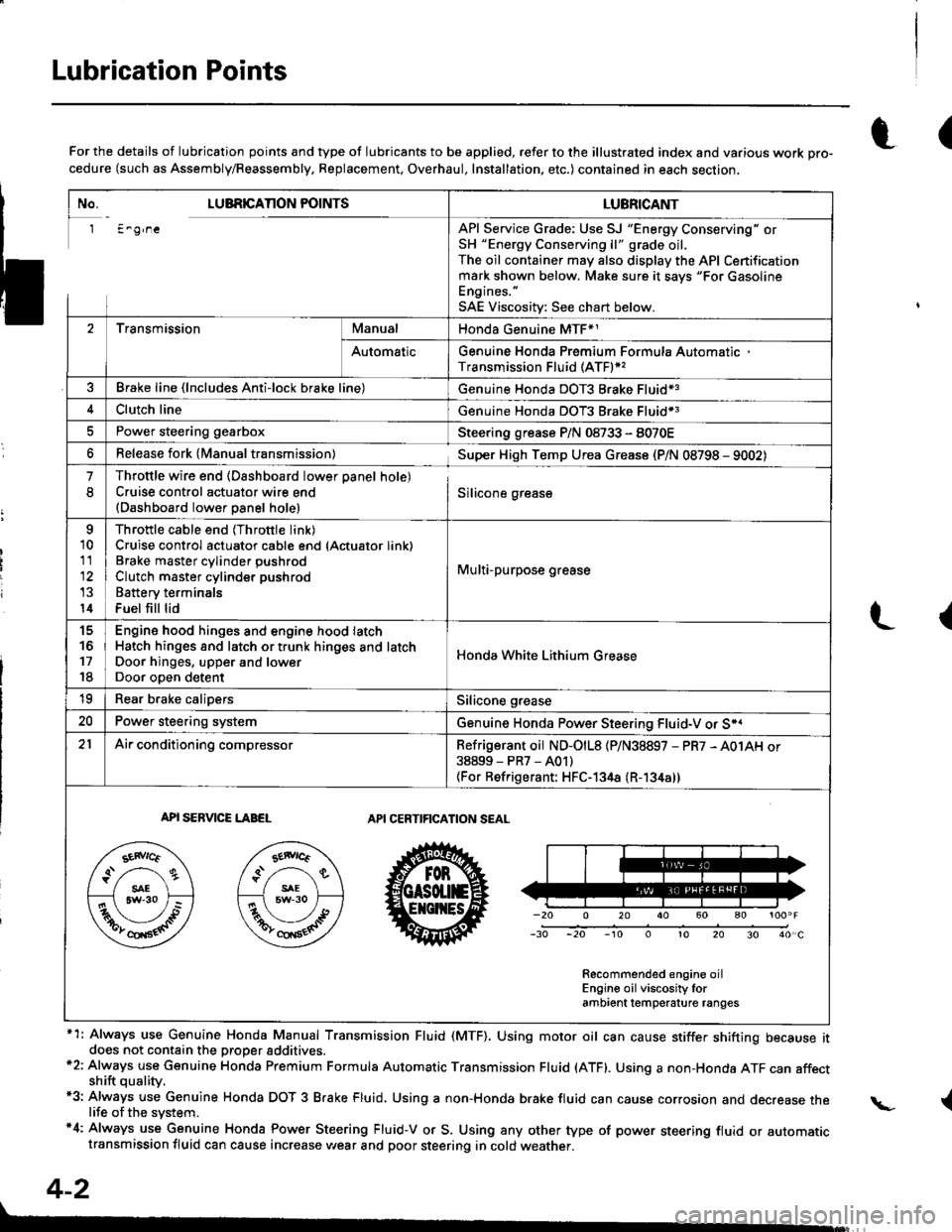
Lubrication Points
No. LUBRICAnON POINTSLUBRICANT
1 E^g,neAPI Service Grade: Use SJ "Energy Conserving" orSH "Energy Conserving ll" grade oil,The oil container may also display the API Certificationmark shown below. Make sure it savs "For GasolineEngines. "
SAE Viscositv: See chart below.
2TransmissionManualHonda Genuine MTF*1
AutomaticGenuine Honda Premium Formula AutomaticTransmission Fluid (ATF)*,
Brake line (lncludes Anti-lock brake line)Genuine Honda DOT3 Brake Fluid13
Clutch lineGenuine Honda DOT3 Brake Fluid*3
Power steering gearboxSteering grease P/N 08733 - 8070E
Release fork lManual transmission)Sup€r High Temp Urea Grease (P/N 08798 - 9002)
1
8
Throttle wire end (Dashboard lower oanel hole)Cruise control actuator wire end(Dashboard lower Danel hole)Silicone grease
o
10
11
14
Throttle cable end (Throttle link)Cruise control actuator cable end (Actuator link)Brake master cvlinder oushrodClutch master cylinder pushrod
Battery terminals
Fuel fill lid
Multi-purpose grease
to
17
18
Engin6 hood hinges and engine hood latchHatch hinges 8od latch or trunk hinges and latchDoor hjnges, upper and lowerDoor ooen detent
Honda White Lithium Grease
19Rear b.ake calipersSilicone grease
20Power steering systemGenuine Honda Power Steering Fluid-V or S*.
21Ai|' conditioning compressorRefrigerant oii ND-O|L8 {P/N38897 - PR7 - A01AH or38899-PR7-A01)(For Refrigerant: HFC-134a (R- 134a))
API SERVICE LABELAPI CERTIFICATION SEAL
Recommended engine oilEngin€ oil viscosity lorambrent lemperature ranges
r(For the details of lubrication points and type of lubricants to be applied, refer to the illustrated index and various work Dro-cedure (such as Assembly/Reassembly, Replacement, Overhaul, Installation. etc.) contained in each section,
*1: Always use Genuine Honda Manual Transmission Fluid (MTF). Using motor oil can cause stiffer shifting because itdoes not contain the proper addtuves.*2: Always use Genuine Honda Premium Formula Automatic Transmission Fluid (ATF). Using a non-Honda ATF can affectshift quality.*3: Always use Genuine Honda DOT 3 B.ake Fluid, Using a non-Honda brake fluid can cause corrosion and decrease thelife of the system.'4: Always use Genuine Honda Power Steering Fluid-V or S. Using any other type of power steering fluid or automatictransmission fluid can cause increase v,/ear and poor steering in cold weather.
L(
{
4-2
Page 52 of 1681
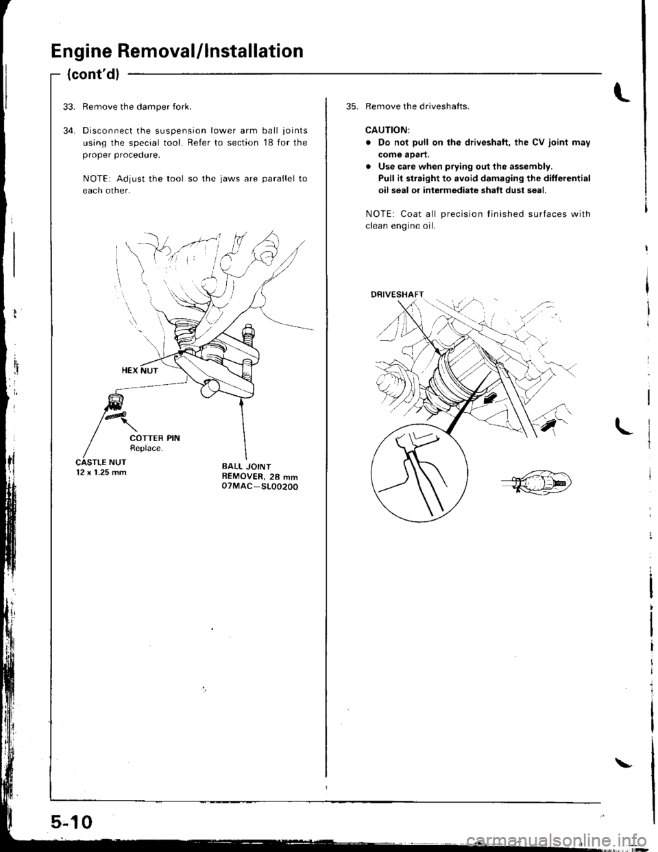
Engine Removal/lnstallation
(cont'dl
34.
Remove the damper {ork.
Disconnect the suspension lower arm ball joints
using the special tool. Refer to section '18 for the
proper procedure.
NOTE: Adjust the tool so the jaws are parallel to
each other.
12 x 1.25 mm
5-jl0
\
35. Remove the driveshafts.
CAUTION:
. Do not pull on the driveshaft, the CV joint may
come aoart.
. Use care when prying out the assembly.
Pull it straight to avoid damaging the differential
oil seal or intermediate shaft dust seal.
NOTE: Coat all precision Iinished surfaces with
clean enoine oil.
,{:
DRIVESHAFT/.-:
/
Page 67 of 1681
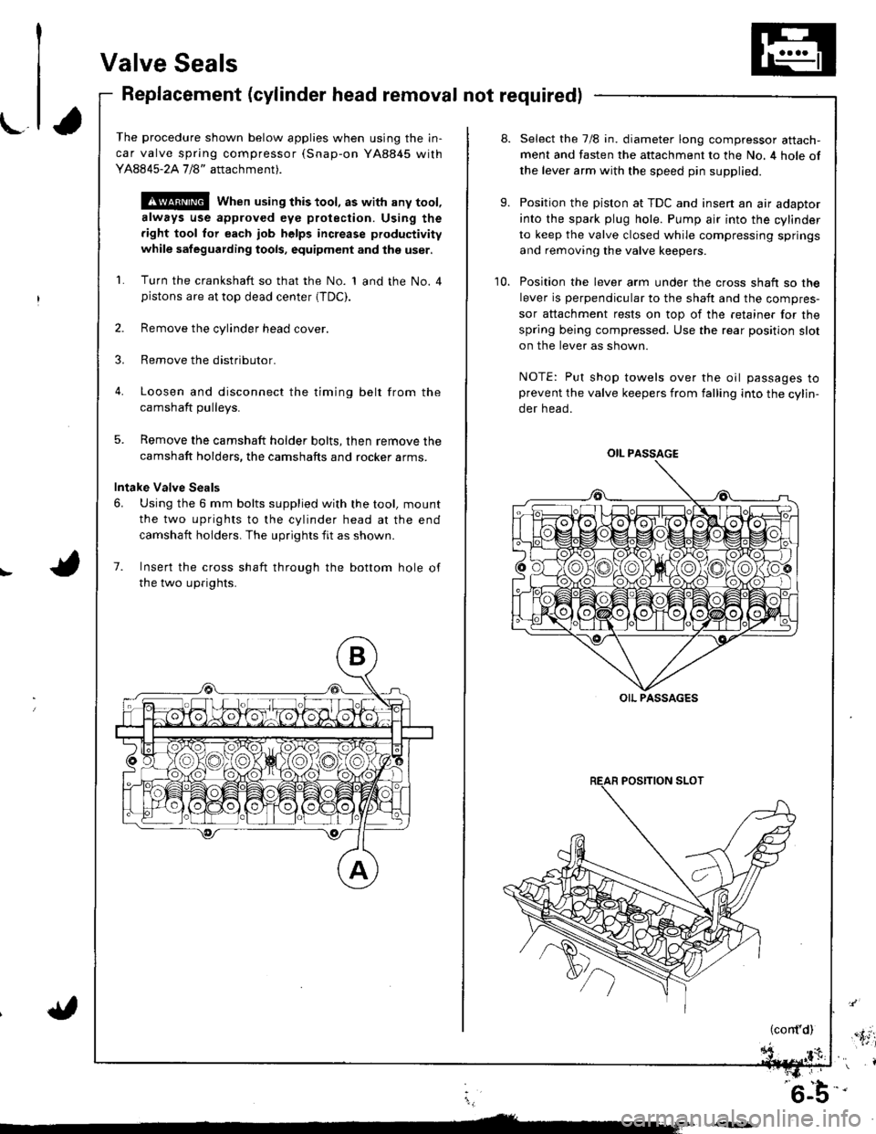
Valve Seals
Replacement (cylinder head removal not required)
The procedure shown below applies when using the in-
car valve spring compressor (Snap-on YA8845 with
Y AAA45-2A 1 /8" attachment).
!@@ When using this tool, as with any tool,
always use approved eye protection. Using the
fight tool tor each job helps increase productivity
while safeguarding tools, equipment and ihe user.
Turn the crankshaft so that the No. 1 and the No. 4pistons are at top dead center (TDC).
Remove the cylinder head cover.
Remove the distributor.
Loosen and disconnect the timinq belt from the
camshaft oullevs.
5. Remove the camshaft holder bolts, then remove the
camshaft holders, the camshafts and rocker arms.
Intake Valve Seals
6. Using the 6 mm bolts supplied with the tool, mount
the two uprights to the cylinder head at the end
camshaft holders. The uprights fit as shown.
7. Insert the cross shaft through the bottom hole of
the two uprights.
8.
9.
10.
Select the 7/8 in. diameter long compressor attach-
ment and fasten the attachment to the No. 4 hole of
the lever arm with the speed pin supplied.
Position the piston at TDC and insen an air adaptor
into the spark plug hole. Pump air into the cylinder
to keep the valve closed while compressing springs
and removing the valve keepers.
Position the lever arm under the cross shaft so the
lever is perpendicular to the shaft and the compres-
sor attachment rests on top of the retainer for the
spring being compressed. Use the rear position slot
on the lever as shown.
NOTE: Put shop towels over the oil passages toprevent the valve keepers from falling into the cylin-
der head.
OIL PASSAGE
OIL PASSAGES
(cont'd),'.itil
i,
'6-b-'
Page 69 of 1681
-1,
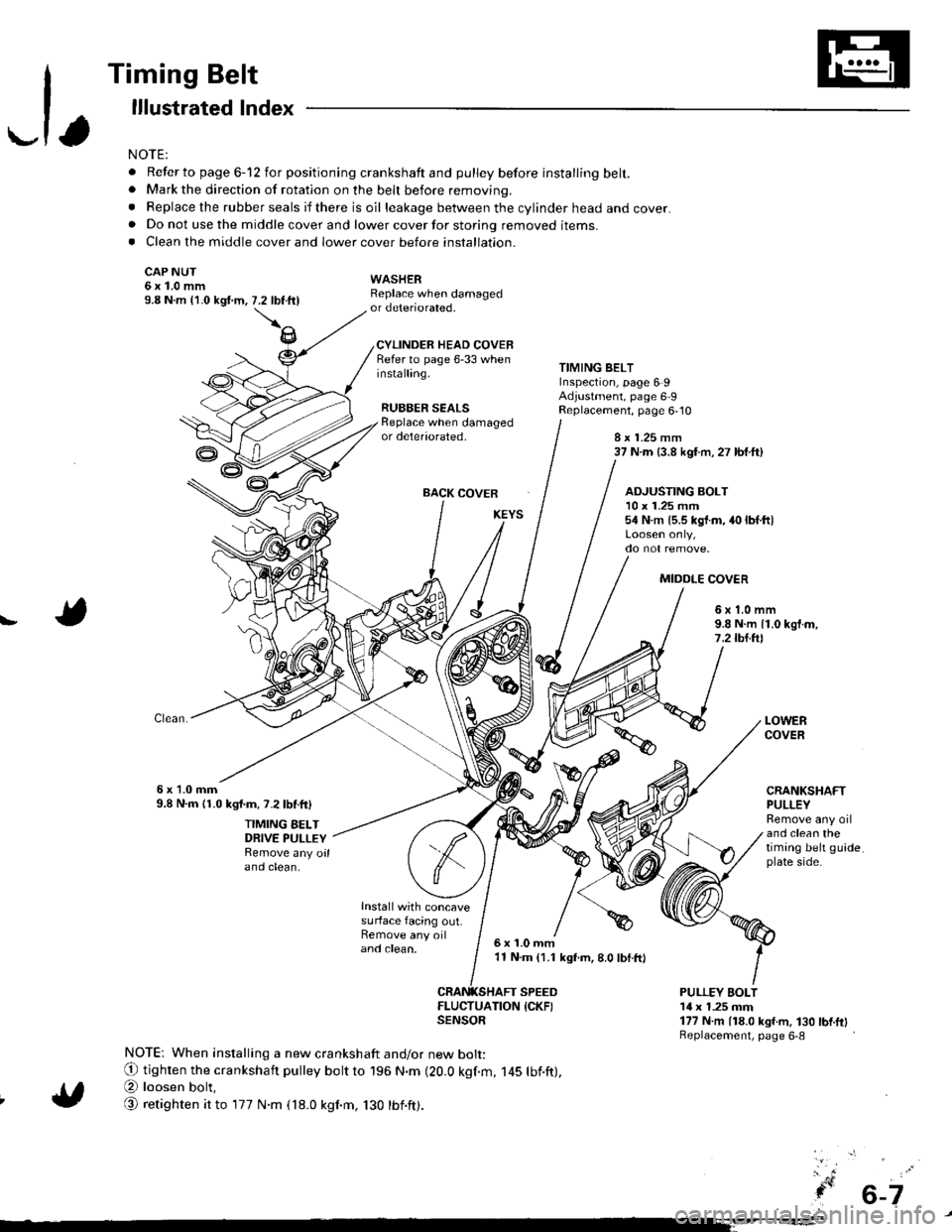
Timing Belt
lllustrated lndex
NOTE:
. Refer to page 6-12 for positioning crankshaft and pulley before installing belt.. Mark the direction of rotation on the beh before removing.
. Replace the rubber seals if there is oil leakage between the cylinder head and cover.. Do not use the middle cover and lower cover for storing removed items.. Clean the middle cover and lower cover before installation.
CAP NUT6x1.0mm9.8 N.m {'1.0 kgi.m,
WASHERReplace when damagedor deteriorated.
CYLINDER HEAD COVERRefer to page 6-33 wheninstalling.
RUBBER SEALS
7.2 tbftll
TIMING BELTInspection, page 6 9Adjustment, page 6 9Replacement, page 6,10Beplace when damagedor deteriorated,8 x 1.25 mm37 N.m (3.8 kgf.m, 27 lbf.ft)
BACK COVER
Install with concavesurface facing out.Remove any oiland clean,
ADJUSTING BOLT10 x 1.25 mm54 N.m {5.5 kgt.m, 40 lbf.ltl
MIDDLE COV€R
!6x1.0mm9.8 N.m {1.0 kgf.m,7.2lbl.ftl
6x 1.0mm9.8 N.m 11.0 kgl.m, 7.2lbf.ftl
TIMING BELTDRIVE PULLEYRemove any oilano ctean.
LOWERCOVER
CRANKSHAFTPULLEYRemove any oiland clean thetiming belt guideplate side.
6x1.0mm'11 N.m (1.1 kgf.m, 8.0 lbI.ft)
SPEED
ItEi:lufrroN {cKF)
NOTE: When installing a new crankshaft and/or new bolt:
O tighten the crankshaft pulley bott to 196 N.m (20.0 kgf.m, 145 tbf.ft),
@ loosen bolt,
@ retighten it to 177 N.m (18.0 kgnm, 130 tbnft).
PULLEY EOLT14 x 1.25 mm177 N.m (18.0 kgf.m, 130 bnftlReplacement, page 6-8
6-7
Page 70 of 1681
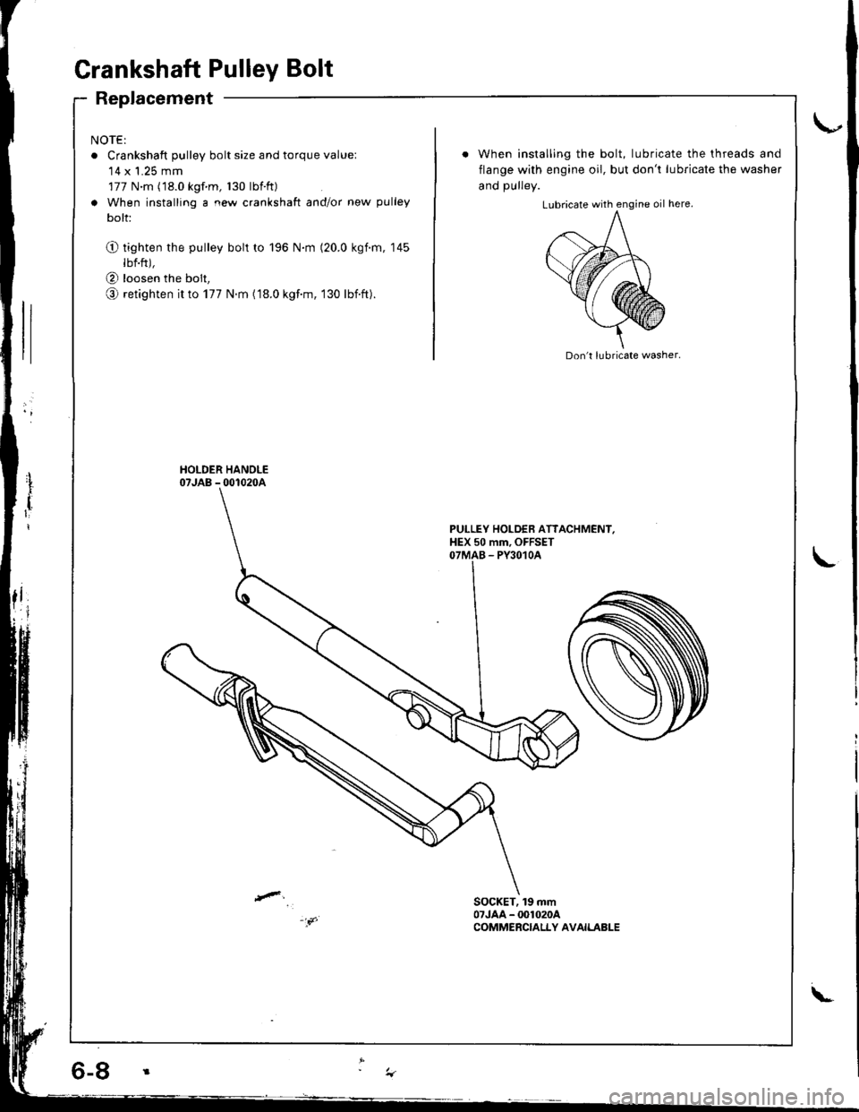
Grankshaft Pulley Bolt
Replacement
NOTE:
o Crankshaft pulley bolt size and torque value:'14 x 1.25 mm
177 N.m (18.0 kgf m, 130 lbtft)
a When installing a new crankshaft and/or new pulley
bolt:
O tighten the pulley bolt to 196 N.m (20.0 kgim, 145
lbf.ft),
@ loosen the bolt,
o retighten it to 177 N.m (18.0 kgf.m, 130 lbift).
When installing the bolt, lubricate the threads and
flange with engine oil, but don't lubricate the washer
and DUllev.
Don't lubricate washer.
PULLEY HOLDEB ATTACHMENI,HEX 50 mm, OFFSETOTMAB - PY3O1OA
SOCKET, 19 mm07JAA - @1020ACOMMERCIALLY AVAILABLE
\-
Page 71 of 1681
\-a
I
I
{
. 6-9
Timing Belt
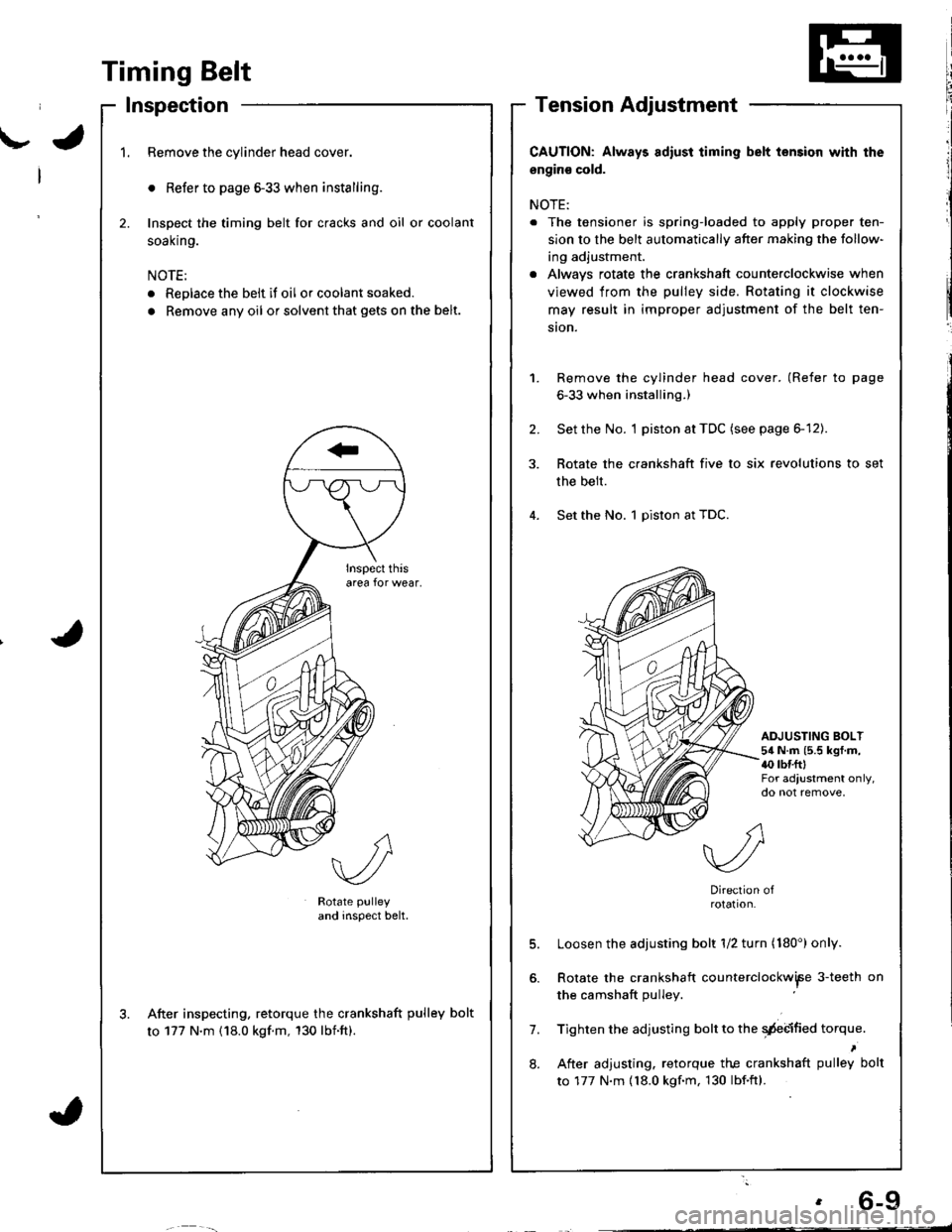
Inspection
1.Remove the cylinder head cover.
o Refer to page 6-33 when installing.
Inspect the timing belt for cracks and oil or coolant
soal(n9.
NOTE:
. Replace the belt if oil or coolant soaked.
. Remove any oil or solvent that gets on the belt.
2.
Rotate pulley
and inspect belt.
After inspecting. retorque the crankshaft pulley bolt
to 177 N'm (18.0 kgf.m, 130 lbnft).
CAUTION: Always adiust iiming belt lension with the
engin€ cold.
NOTE:
. The tensioner is spring-loaded to apply proper ten-
sion to the belt automatically after making the follow-
ing adjustment.
. Alwavs rotate the crankshaft counterclockwise when
viewed from the pulley side. Rotating it clockwise
may result in improper adjustment of the belt ten-
ston.
Remove the cylinder head cover. (Refer to page
6-33 when installing.)
Set the No. I piston at TDC (see page 6-12).
Rotate the crankshaft five to six revolutions to set
the belt.
Set the No. 1 piston at TDC.
1.
2.
ADJUSTING BOLT54 N.m (5.5 kgf.m,{0 rbr.fttFor adjustment only,do not remove,
7.
8.
Direction ofrotation.
Loosen the adjusting bolt 1/2 turn (180') only.
Rotate the crankshaft counterclockwiFe 3-teeth on
the camshaft pulley
Tighten the adjusting bolt to the qdebified torque.
After adjusting. retorque the crankshaft pulley bolt
to 177 N.m {18.0 kgf.m, 130 lbf.ftl.
Page 78 of 1681
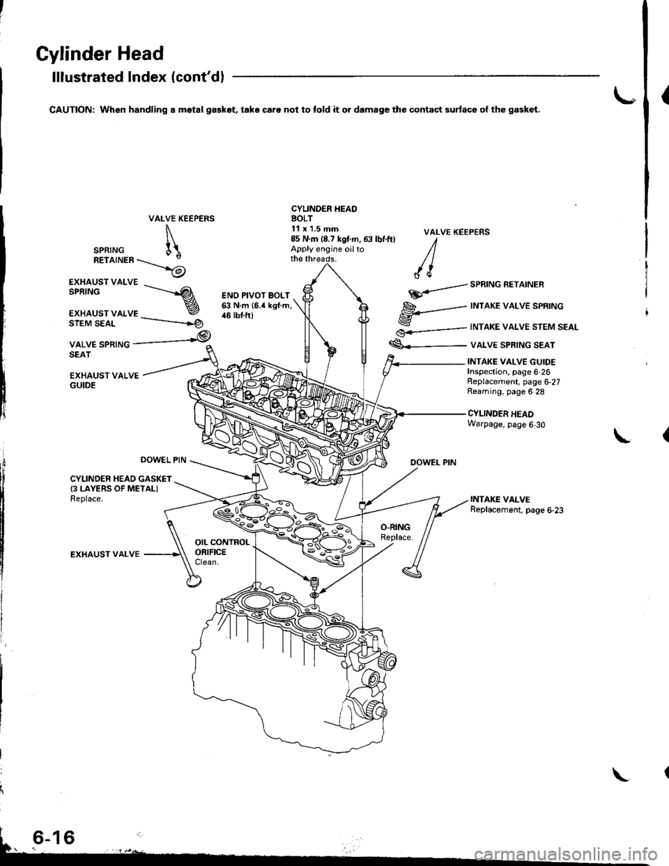
Gylinder Head
lllustrated Index (cont'd)
CAUTION: When handling a mstal ga€kot, take care not to fold it o. damage the contact surfac6 ol the gasket.{
VALVE KEEPERS
\
SPRTNG [\RETaTNER\_>6
CYLINDER IIEAOAOLT11 x'1.5 mm
EXHAUST VALVE
EXHAUST VALSPRINGs------.--
r
€.-=---
€<_-
VALVE KEEP€NS
DOWEL PIN
SPRING AEIAINER
INTAKE VALVE SPRING
INTAKE VALVE STEM SEAL
VALVE SPRING SEAT
ENO PIVOT BOLT63 N.m {6.4 kgf.m,46 tbt.ftlSIEM SEAL
VALVE SPRINGSEAT
-----------rg
,@
EXHAUST VALVEGUIDE
INTAKE VALVE GUIDEInspection. page 6 26Replacement, page 6,27Reaming, page 6 28
CYLINDER HEADWarpage, page 6,30
L
DOWEL PIN
CYLINDER HEAD GASKET(3 LAYERS OF METALIReplace.
EXHAUST VALVE
85 N.m (8.7 kgtm, 63 lbf.ft) IApply engine oilto /lthe threads. / |
/ {e
\
Page 80 of 1681
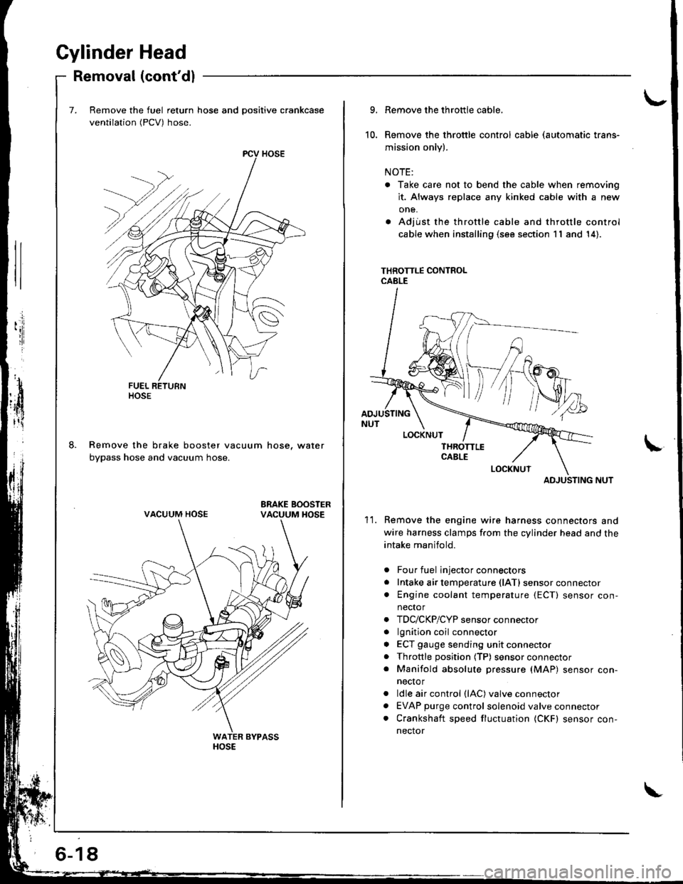
Gylinder Head
Removal (cont'dl
Remove the fuel return hose and positive crankcase
ventilation (PCV) hose.
Remove the brake booster vacuum hose, water
bypass hose and vacuum hose.
ltosE
VACUUM HOSE
6-18
10.
9.
11.
Remove the throttle cable,
Remove the throttle control cable (automatic trans-
mission only).
NOTE:
. Take care not to bend the cable when removing
it. Always replace any kinked cable with a new
one.
. Adjust the throttle cable and throttle control
cable when installing (s€e section 11 and 14).
THROTTLE CONTROLCABLE
ADJUSTING NUT
Remove the engine wire harness connectors and
wire harness clamps f.om the cylinder head and the
intake manifold.
Four fuel injector connectors
Intake air temperature (lATl sensor connector
Engine coolant temperature {ECT) sensor con,
nector
TDC/CKP/CYP sensor connector
lgnition coil connector
ECT gauge sending unit connector
Throttle position (TP) sensor connector
Manifold absolute pressure (MAP) sensor con-
necto r
ldle air control (lAC) valve connector
EVAP purge control solenoid valve connector
Crankshaft speed fluctuation (CKF) sensor con-
nector
a
a
a
a
a
a
a
a
ADJUSTING
Page 87 of 1681
\-
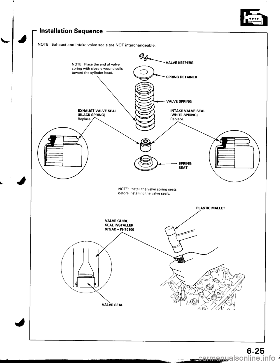
Installation Sequence
Exhaust and intake valve seals are NOT interchanoeable.
NOTE: Place the end of valvespring with closely wound coilstoward the cylinder head.
EXHAUST VALVE SEALIBLACK SPRING}Replace.
@A..'..--uoruEKEEPER'
9-...-'PRTNGREYATNER
VALVE SPRING
INTAKE VALVE SEALIWHITE SPRINGIReplace.
I
PLASTIC MALLET
VALVE GUIDESEAL INSTALLER07GAD - PH70100
,@.t.'( (Sz) I<-- SPRING
V SEAT
NOTE: lnstall the valve spring seatsbefore installing the valve seals.
6-25
Page 88 of 1681
Valve Installation'alve Inslallauon -
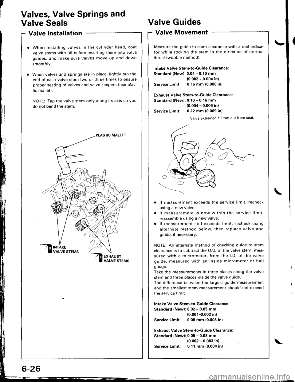
When installing valves in the cylinder head, coat
valve stems with oil belore inserting them into valve
guides, and make sure valves move up and down
smoothly.
When valves and springs are in place, lightly tap the
end of each valve stem two or three times to ensure
proper seating of valves and valve keepers (use plas
tic mallet).
NOTE: Tap the valve stem only along lts axrs so you
do not bend the stem.
PLASTIC MALLET
Valves, Valve Springs and
Valve SealsValve
Valve
Guides
Movement
\-
L
valve tvtovemenr -
Measure the guide to stem clearance with a dial indica-
tor while rocking the stem in the direction of normal
thrust {wobble method).
lntake Valve Stem-to-Guide Clearance:
Standard {Newlr 0.04 - 0.10 mm
10.002 - 0.004 in)
Service Limit: 0.16 mm {0.005 in)
Exhaust Valve Stem-to-Guide Clearance:
Standard {New}: 0.10 - 0.16 mm
(0.004 - 0.006 inl
Service Limit: 0.22 mm (0.009 in)
Valve extended 10 mm out from seat
lf measurement exceeds the service limit, recheck
usrng a new valve.
lf measurement is now within the service limit,
reassemble using a new valve.
lf measurement still exceeds limit, recheck using
alternate method below, then replace valve and
guide, if necessary.
NOTEr An alternate method of checking guide to stem
clearance is to subtract the O.D. of the valve stem, mea-
sured with a micrometer, from the l.D. o{ the valve
guide, measured with an inside micrometer or ball
ga uge.
Take the measurements in three places along the valve
stem and three places inside the valve guide.
The diiference between the largest guide measurement
and the smallest stem measurement should not exceed
the service limit
lntake Valve Stem-to-Guide Clearance:
Standard (Newl: 0.02 - 0.05 mm
10.001-{.002 inl
Service Limit: 0,08 mm (0.003 in)
Exhaust Valve Stem-to-Guide Clearance:
Standard (New): 0.05 - 0.08 mm
{0.002 - 0.003 in)
Service Limit: 0.11 mm {0.004 in)\