mirror HONDA INTEGRA 1998 4.G User Guide
[x] Cancel search | Manufacturer: HONDA, Model Year: 1998, Model line: INTEGRA, Model: HONDA INTEGRA 1998 4.GPages: 1681, PDF Size: 54.22 MB
Page 865 of 1681
Mirrors
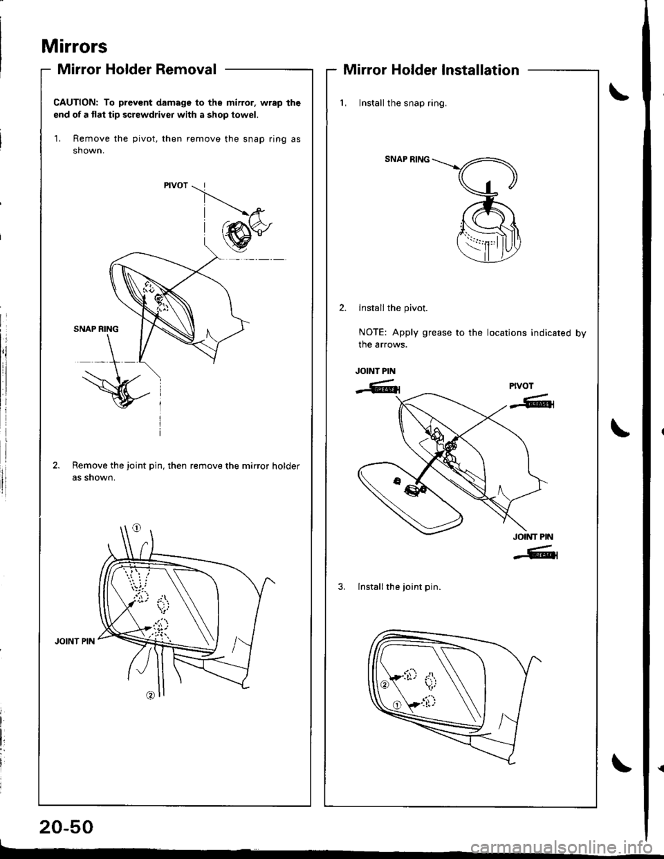
Mirror Holder Removal
20-50
Mirror Holder Installation
CAUTION: To prevent damage to the mirror, wrap the
end of a flat tip screwdriver with a shop towel.
1, Remove the pivot, then remove the snap ring as
shown.
Remove the joint pin, then remove the mirror holder
as snown.
_.'ta,i
{i'}
l, Install the snap ring.
SNAP RING
Install the pivot.
NOTE: Apply grease to the locations indicated by
the arrows.
JOINT PIN
-6lrPIVOT
-6t1
JOINT PIN
-6tl
3, lnstall the joint pin.
Page 866 of 1681
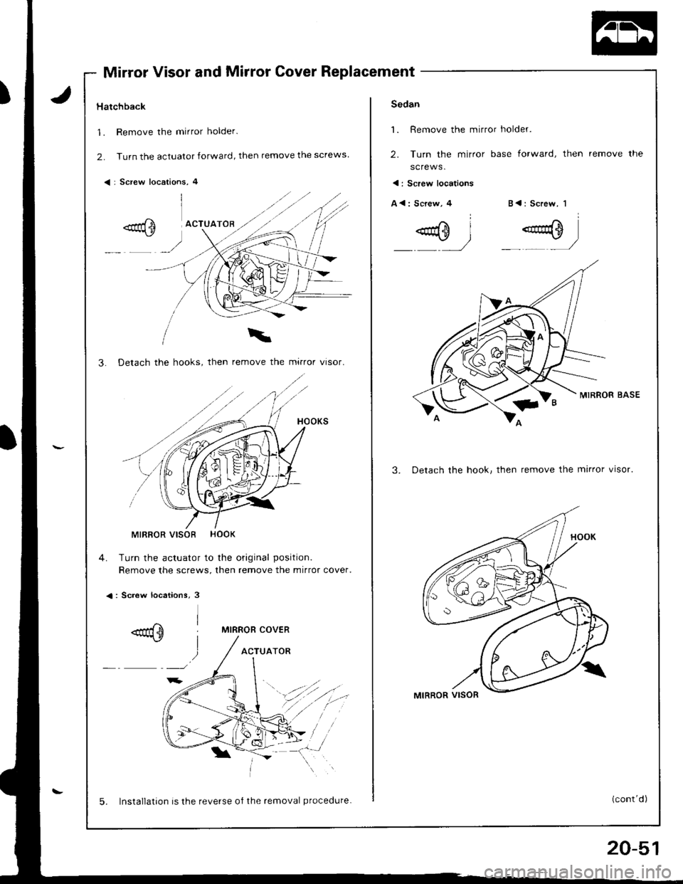
Mirror Visor and Mirror Cover Replacement
Hatchback
1. Remove the mirror holder.
2. Turn the actuator forward, then remove the screws
< : Screw locations, 4
3. Detach the hooks, then remove the mirror visor.
MIRROR VISOR HOOK
4. Turn the actuator to the original position.
Remove the screws, then remove the mirror cover.
<: Screw locations, 3
MIRROR COVER
ACTUATOR
5. Installation is the reverse of the removal procedure.
20-51
Sedan
1. Remove the mirror holder.
2. Turn the mirror base forward, then
screws.
remove the
< : Screw locations
A<: Screw,4B<: Screw, 1
MIRROR BASE
3. Detach the hook, then remove the mirror visor.
Page 867 of 1681
![HONDA INTEGRA 1998 4.G User Guide Replacement (contd)
4. Remove the actuator, then remove the screws.
<: Screw locations
A<: Screw, 3 B<: Screw, 2C { : Screw, 1
.aqm I- r/
.0=-l .g}_,,]
5.Turn the mirror base as shown, then remove HONDA INTEGRA 1998 4.G User Guide Replacement (contd)
4. Remove the actuator, then remove the screws.
<: Screw locations
A<: Screw, 3 B<: Screw, 2C { : Screw, 1
.aqm I- r/
.0=-l .g}_,,]
5.Turn the mirror base as shown, then remove](/img/13/6069/w960_6069-866.png)
Replacement (cont'd)
4. Remove the actuator, then remove the screws.
<: Screw locations
A<: Screw, 3 B<: Screw, 2C { : Screw, 1
.aqm I- r'/
'.0=-l .g}_,,]
5.Turn the mirror base as shown, then remove Ine mtr
ror cover
MIRROR AASE
6. Installation is the reverse oI the removal procedure.
ACTUATOR
MIRROR COVEB
Mirrors
Mirror Visor and Mirror CoverRearview Mirror Replacement
:
rl
rl
I
20-52
L
1. Pry the cover off using the end of a flat tip screw-
drive r.
CAUTION: To prevent damage to the mirror and
cover, wrap the end ol the screwdriver with a shop
towel.
2. Remove the screws, then remove the rearview
mirror.
REARVIEWMIRROR
3. lnstallation is the reverse of the removal orocedure.
SHOP TOWEL
Page 913 of 1681
Headliner
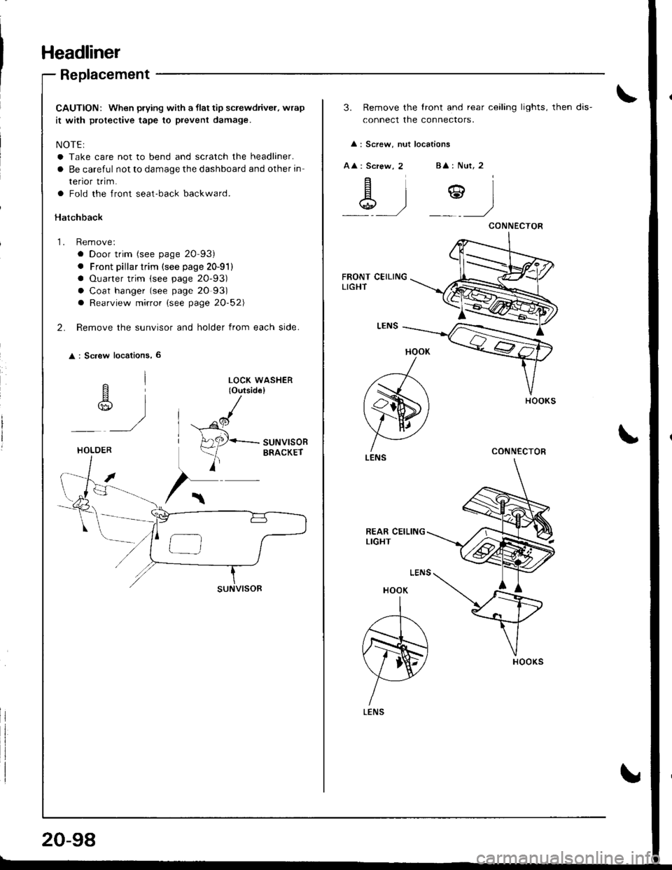
Replacement
CAUTION: When prying with a llat tip screwdriver. wrap
it with protective tape to prevent damage.
NOTE:
a Take care not to bend and scratch the headliner.
a Be careful not to damage the dashboard and other in
renor rr|m.
a Fold the front seat-back backward.
Hatchback
1. Remove:
a Door trim (see page 20-93)
. Front pillar trim (see page 20-91)
a Ouarter trim (see page 20-93)
a Coat hanger (see page 20 93)
a Rearview mirror (see page 20-52\
2. Remove the sunvisor and holder from each side.
: Sc.ew locations, 6
^l
r$,,
)
LOCK WASHER(o{rtsid€}
^cl
H
A2P-suNvlsoR
)
ERACKErHOLOER
20-98
3. Remove the lront and rear ceiling lights, then dis-
connect the connectors.
: Screw, nut locations
A : Screw, 2B : Nut, 2
\g .)Y)
HOOK
)
(s)
V AI ./
LENS
HOOK
A
N)
YLENS
CONNECTOR
CONNECTOR
Page 915 of 1681
Headliner
Replacement (cont'd)
LEFT OUARTER PILLARTRIM PANEL
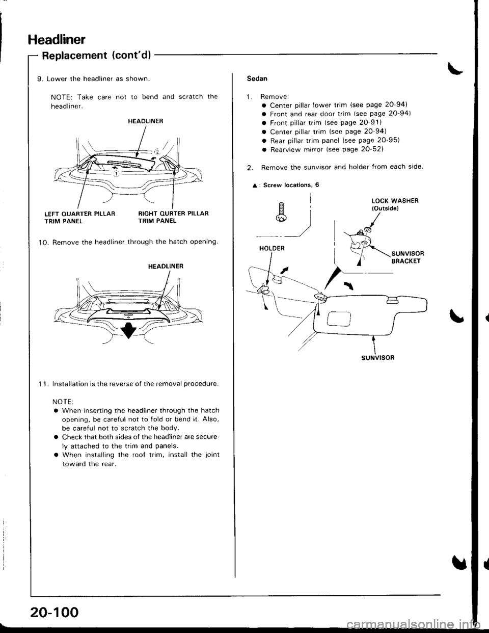
9. Lower the headliner as shown.
NOTE: Take care not to bend and scratch the
head liner.
RIGHT OURTER PILLARTRIM PANEL
1O. Remove the headliner through the hatch opening
1 1. Installation is the reverse of the removal procedure.
NOTE:
a When inserting the headliner through the hatch
opening, be careful not to lold or bend it. Also,
be careful not to scratch the body.
a Check that both sides o{ the headliner are secure'
ly attached to the trim and panels.
a When installing the rool trim, install the ioint
toward the rear.
HEAOLINER
HEADLINER
20-100
Sedan
1.Rem ove:
a Center pillar lower trim {see page 20-94)
a Front and rear door trim (see page 20-94)
a Front pillar trim lsee page 20 9'.
a Center pillar trim {see page 20 94)
a Rear pillar trim panel (see page 20-95)
a Rearview mirror (see page 20 52)
Remove the sunvisor and holder from each side.
: Screw locations, 6
elA]*)
HOLDER
suNVlsoR
LOCK WASHER
lOutside)
,al
(
Page 1091 of 1681
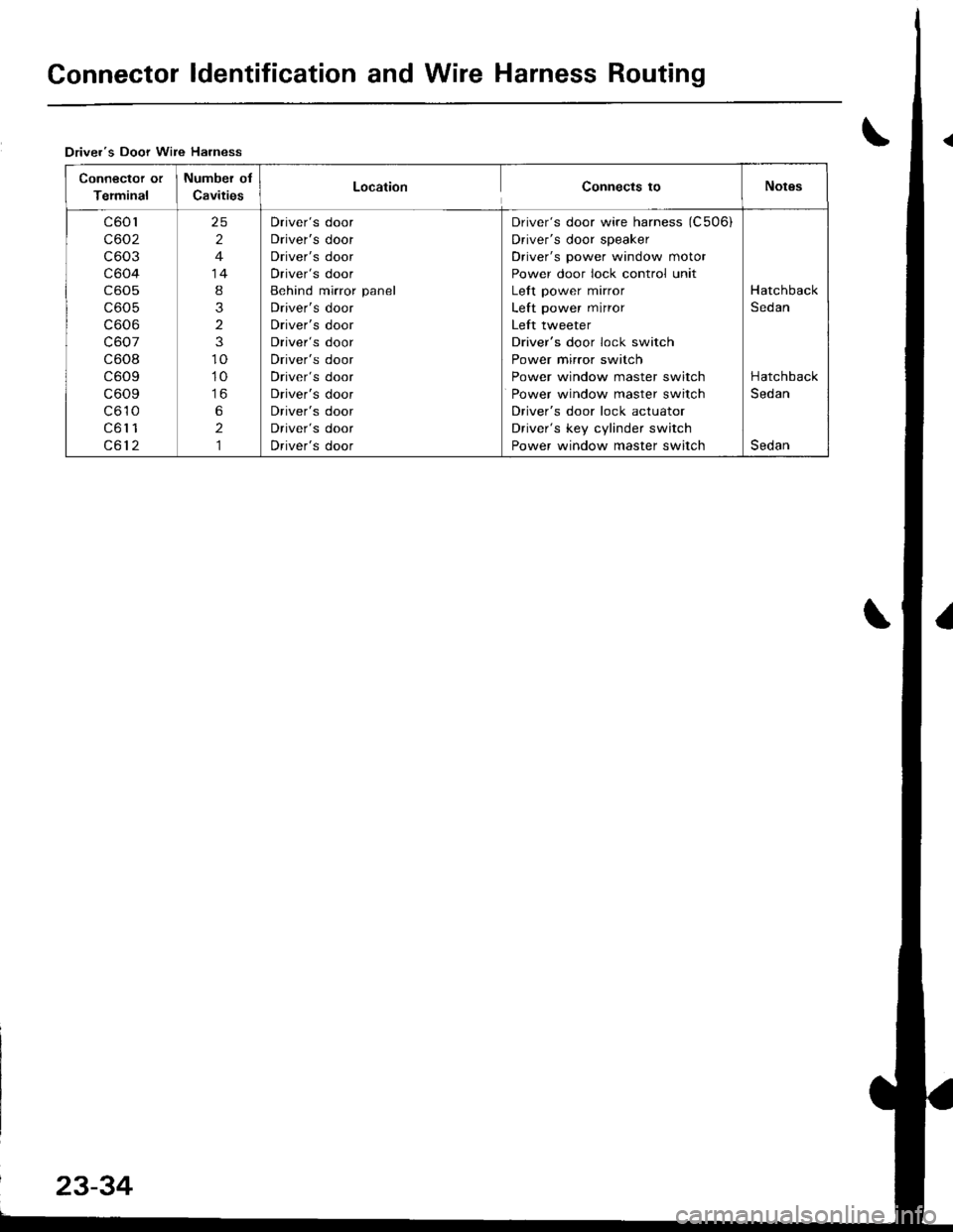
Connector ldentification and Wire Harness Routing
Driver's Door Wire Harness
Connector or
Terminal
Number of
CavitiesLocationConnects toNotgs
c601
c602
c603
c604
c605
c605
c606
c607
c608
c609
c609
c610
c61 1
c612
25
2
4
14
8
3
2
3
10
10
to
6
2,]
Driver's door
Driver's door
Driver's door
Driver's door
Behind mirror panel
Driver's door
Driver's door
Driver's door
Driver's door
Driver's door
Driver's door
Driver's door
Driver's door
Driver's door
Driver's door wire harness (C506i
Driver's door speaker
Driver's power window motor
Power door lock control unit
Left power mirror
Left power mirror
Left tweeter
Driver's door lock switch
Power mirror switch
Power window master switch
Power window master switch
Driver's door lock actuator
Driver's key cylinder switch
Power window master switch
Hatchback
Sedan
Hatchback
Sedan
Sedan
Page 1093 of 1681
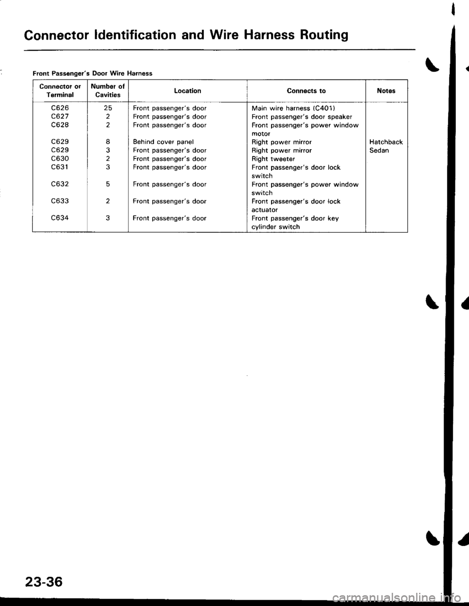
Connector ldentification and Wire Harness Routing
\Front Passengel's Door wire Harness
Connoctot ot
Terminal
Number oI
CavitiesLocationConnects toNotes
c627
c62I
c6 29
c629
c630
c631
c632
c633
c634
25
2
2
8
2
3
5
2
3
Front passenger's door
Front passenger's door
Front passenger's door
Behind cover panel
Front passenger's door
Front passenger's door
Front passenger's door
Front passenger's door
Front passenger's door
Front passenger's door
Main wire harness (C401)
Front passenger's door speaker
Front passenger's power window
motor
Right power mirror
Right power mirror
Right tweeter
Front passenger's door lock
switch
Front passenger's power window
swrrcn
Front passenger's door lock
actuator
Front passenger's door key
cylinder switch
Hatchback
Sedan
Page 1281 of 1681
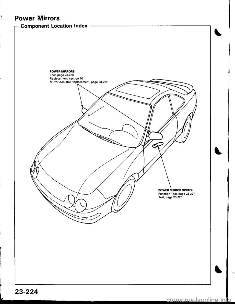
Power Mirrors
Component LocationIndex
I
POWER MIRRORST€st, page 23-228Replacom6nt, s6ction 20Mirror Actuator Repl6cemenl, page 23-229
FOWER MIRROR SWTCHFunction Test, page 23-227Test. page 23-226
23-224
Page 1282 of 1681
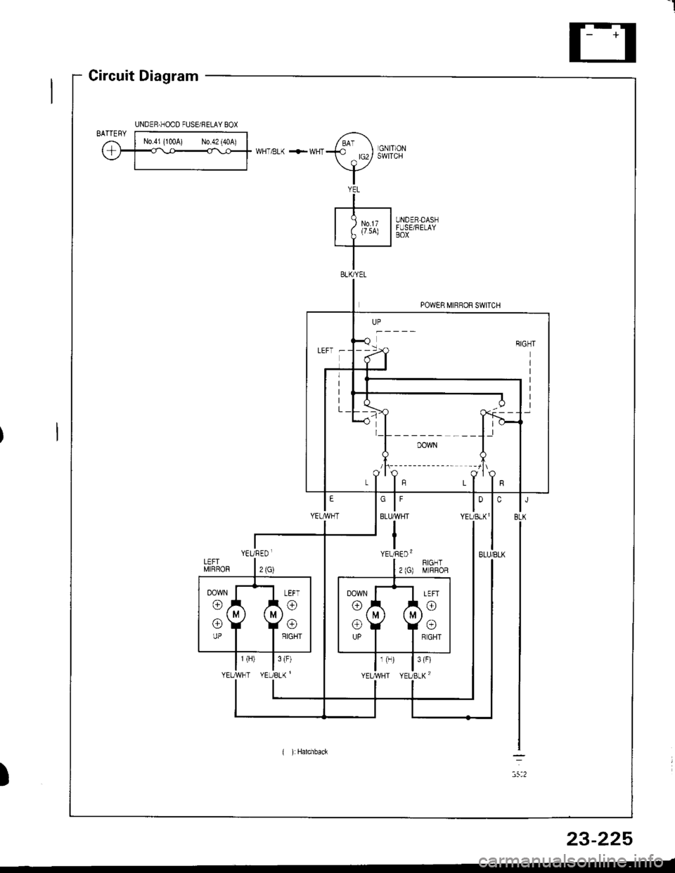
I
Circuit Diagram
UNDER,DASNFUSE/RELAYBOX
YEL
-+-----t
I Zu',x I.I--
POWER MIRROR SWITCH
)
UNDER.HOOD FUSE/FELAY BOX
LEFT -
l_L______ ___l.l
/t\-------- --lt\
YEURED.
( ):Hatchback
23-225
Page 1283 of 1681
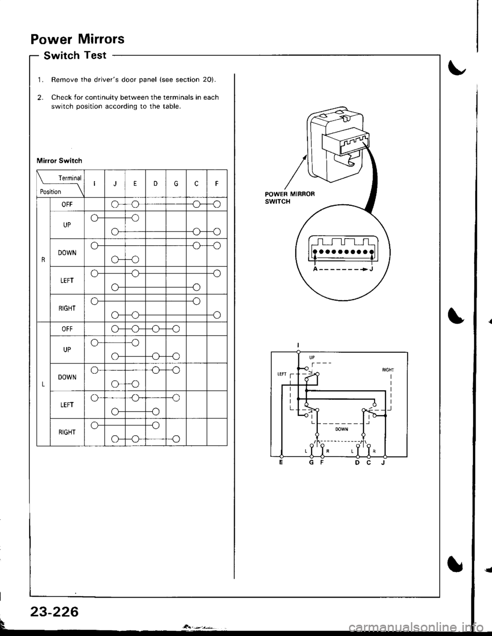
Power Mirrors
Switch Test
1.
2.
Remove the driver's door panel (see section 2O).
Check for continuity between the terminals in each
switch position according to the table.
Mirror Switch
aaaaaaaa
A-------->J
Terminal
Position \
EDGcF
R
OFFo--o
UPo--o
-oo--G
DOWNo--o
G-o
LEFTo--o
o--o
RIGHTo--o
-oo-
L
OFFo--o
UPo--o
-oo-
DOWNo--o
o--o
LEFTo--o
o--o
RIGHTo--o
-oo-
23-226