fuse chart HONDA INTEGRA 1998 4.G Workshop Manual
[x] Cancel search | Manufacturer: HONDA, Model Year: 1998, Model line: INTEGRA, Model: HONDA INTEGRA 1998 4.GPages: 1681, PDF Size: 54.22 MB
Page 467 of 1681
![HONDA INTEGRA 1998 4.G Workshop Manual Troubleshooting Procedures
Checking the Diagnostic Trouble Code (DTC)
with an OBD ll Scan Tool or th€ Honda PGM Tester
When the TCM senses an abnormality in the input or output systems, the lD,] ind HONDA INTEGRA 1998 4.G Workshop Manual Troubleshooting Procedures
Checking the Diagnostic Trouble Code (DTC)
with an OBD ll Scan Tool or th€ Honda PGM Tester
When the TCM senses an abnormality in the input or output systems, the lD,] ind](/img/13/6069/w960_6069-466.png)
Troubleshooting Procedures
Checking the Diagnostic Trouble Code (DTC)
with an OBD ll Scan Tool or th€ Honda PGM Tester
When the TCM senses an abnormality in the input or output systems, the lD,] indicator light in the gauge assembly will
blink. When the 16p Data Link Connector (DLC) (located under the dash on the passenger side) is connected to the OBD ll
Scan Tool or Honda PGM Taster as shown, the scan tool or tester will indicate the Diagnostic Trouble Code (DTC) when
the ignition switch is turned ON {ll}.
When the !r indicator light has been reported on, connect the OBD ll Scan Tool confirming to SAE J1978 or Honda PGM
Tester to the DLC (16P) behind the ashtray. Turn the ignition switch ON (ll) and observe the DTC on the screen ofthe OBD
ll Scan Tool or Honda PGM Tester. After determining the DTC, refer to the electrical system Symptom-to-Component
Chart on pages 14-54 and 14-55.
NOTE: SeetheOBDll ScanTool orHonda PGM Tester user's manual for specific instructions.
OBD-IlSCAN TOOL orHONDA PGM TESTER
Some PGM-Fl problems will also make the lol indicator light come on. After repairing the PGM-Fl system. disconnect the
BACK Up fuse (7.5 A) in the under-hood fuse/relay box for more than 10 seconds to reset the TCM memory, then recheck.
NOTE: Disconnecting the BACK UP fuse also cancels the radio anti-theft code, preset stations and the clock setting. Get
the customer's code number, and make note of the radio presets before removing the fuse so you can reset them
uJ trr
ulu
ai
14-50L
DATA LINK CONNECTOR (16P)
I
il
lt
rJq
Page 468 of 1681
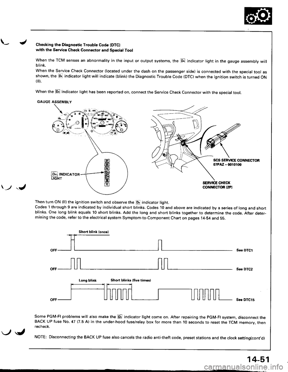
L./Checking th€ Diagnostic Trouble Codo (DTC)
with the Sowica Check Connector and Special Tool
When the TCM senses an abnormality in the input or output systems, the [D;l indicator light in the gauge assembly willblink.
When the Service Check Connector (located under the dash on the passenger side) is connected with the special tool asshown, the E1T indicator light will indicate (blink) the Diagnostic Troubte Code (DTC) when the ignition switch is turned ON{
}.
When the @ indicator light has been reported on, connect the Service Check Connector with the special toot.
GAUGE ASSEMEI.Y
Then turn ON (ll) the ignition switch and observe the E indicator light.Codes 1 through 9 are indicated by individual short blinks. Codes 1O and above are indicated by a series of long and shortblinks. One long blink equals 10 short blinks. Add the long and short blinks together to determine the code. After deter-mining the code, refer to the electrical system Symptom-to-Component Chart on pages 14-S4 and 55.
\-F;ii^r
) ,J
Se. OTCI
Soo DTC2
Long blinkShort blinb lfive timcsl
Soe DTCl5
Some PGM-FI problems will also make the E indicator light come on. After repairing the PGM-FI system, dasconnect theBACK UP fuse No. 47 (7.5 A) in the under-hood tuse/relay box for more than 1O seconds to reset the TCM memory, thenrecnecK.
NOTE; Disconnecting the BACK UP fuse also cancels the radio anti-theft code, preset stations and the clock setting(cont,d)
Short blink loncsl
\-/ \i,
14-51
Page 497 of 1681
Electrical Troubleshootin g
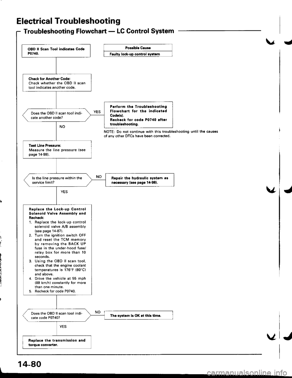
Troubleshooting Flowchart - LC Control System
\.r.Poeribl. C.ua.
control
NOTE: Do not continue with this troubleshootingot any other DTCS have beeo corrected.until thg caus€s
v
t,
I
'I
14-80
Chock lor Anothor Cod6:Check whether the OBD lltool indicates another codo.
P6rform tha TroublorhootingFlowcha for tho indicrladCodolsl.R.ch.ck fof codo P0740 !ft.tt.oublo3hooting.
Does the OBD ll scan tool indi-cate another code?
Tost Line Proisurg:Measure the line pressure (see
pag6 14-98).
R.prir tho hydraulic syltcm !!n.cGsary (soc pago 1+98).ls the line prsssure within theservic€ limit?
Repl!c6 th6 Lock-up ControlSolenoid Velva As3ambly .ndRschock:1. Replace the lock-up controlsolenoid valve y'y'B assembly(see page '!4-87).
2. Turn the ignition switch OFFand reset the TCM memoryby removing the BACK UPfuse in the und€r-hood fuse/rolay box tor more than 10seconos.3. Using the OBD ll scan tool,check that the engine coolanttemperatures is 176'F (80'C)
4. Drive the vehicle at 55 mph(88 km/h) constantly lor rnorethan one mrnute,5. Recheck for code P0740.
Does the OBD ll scan tool indi-cate codo P0740?Tha iy3t6m ir OK .t thi! timc.
V
I
J
Page 498 of 1681
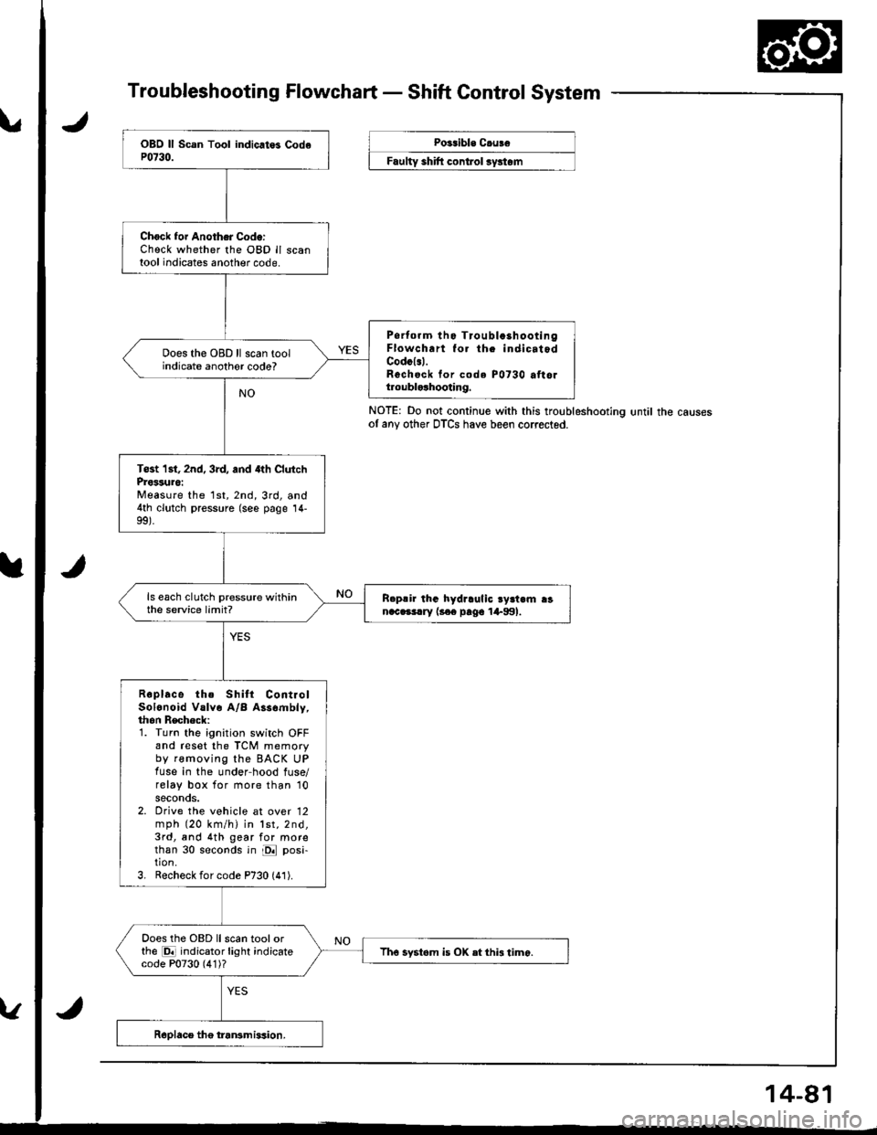
Troubleshooting Flowchart - Shaft Control System
NOTE: Do not continue with this troubleshootlng until the causesof any other DTCS have been corrected.
Chock foi Another Code:Check whether the OBD ll scantool indicates another code.
Psrtorm tho Tioubla3hootingFlowch.rt fo. th. indicatodCodcl.l.Rechsck tor code P0730 attoltroublolhooting.
Does the OBD ll scan toolindicate anothor code?
Tost 1st, 2nd, 3rd, and 4th ClutchProssuro:Measure the 1st,2nd,3rd, and4th clutch pressure (see page 14-
ls each clutch pressure withinthe service limit?R.p!ir lhG hydraulic ry3t.m ranac.3!.ry l3€e pago 1+991.
Roplace the Shilt ContiolSolonoid Valve A/B Assombly,thon Recheck:1. Turn the ignition switch OFFand reset the TCM memoryby removing the BACK UPfuse in the under-hood fuse/relay box for more than '10
seconds.2. Orive the vehicle at over 12mph (20 km/h) in lst,2nd,3rd, and 4th gear for morethan 30 seconds in E posi-tion.3, Recheck for code P730 (41).
Does the OBD llscan toolorthe E indicator light indicatecode P0730 (4'1)?Tho systom is OX etthi3 timo.
Poitible C.uBe
F""lty "hlft ".^t..t ",/"t".
Page 1025 of 1681
J
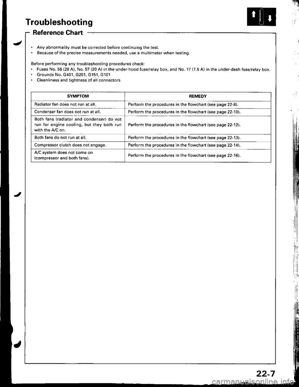
Troubleshooting
Reference Chart
. Any abnormality must be corrected before continuing the test.. Because of the precise measurements needed, use a multimeter when testing.
Before performing any troubleshooting procedures check:. Fuses No, 56 (20 A), No. 57 (20 A) in the under-hood fuse/relay box, and No. 17 {7.5 A) in rhe under-dash fuse/relay box.. Grounds No. G401, G201, G151, G101. Cleanliness and tightness of all connectors
I'IT
I
I
SYMPTOMREMEDY
Radiator fan does not run at all.Perform the procedures in the flowchart {see page 22-8).
Condenser fan does not run at all,Perform the procedures in the flowchart (see page 22-1O1.
Both fans {radiator and condenser) do not
run for engine cooling, but they both run
with the IVC on.
Perform the procedures in the tlowchart (see page 22-12).
Both fans do not run at all.Perform the procedures in the flowchart (see page 22-13).
Compressor clutch does not engage.Perform the procedures in the flowchart (see page 22-14).
l'lc system does not come on
{compressor and both fans).Perform the procedures in the flowchart (see page 22-15).
22-7
Page 1124 of 1681
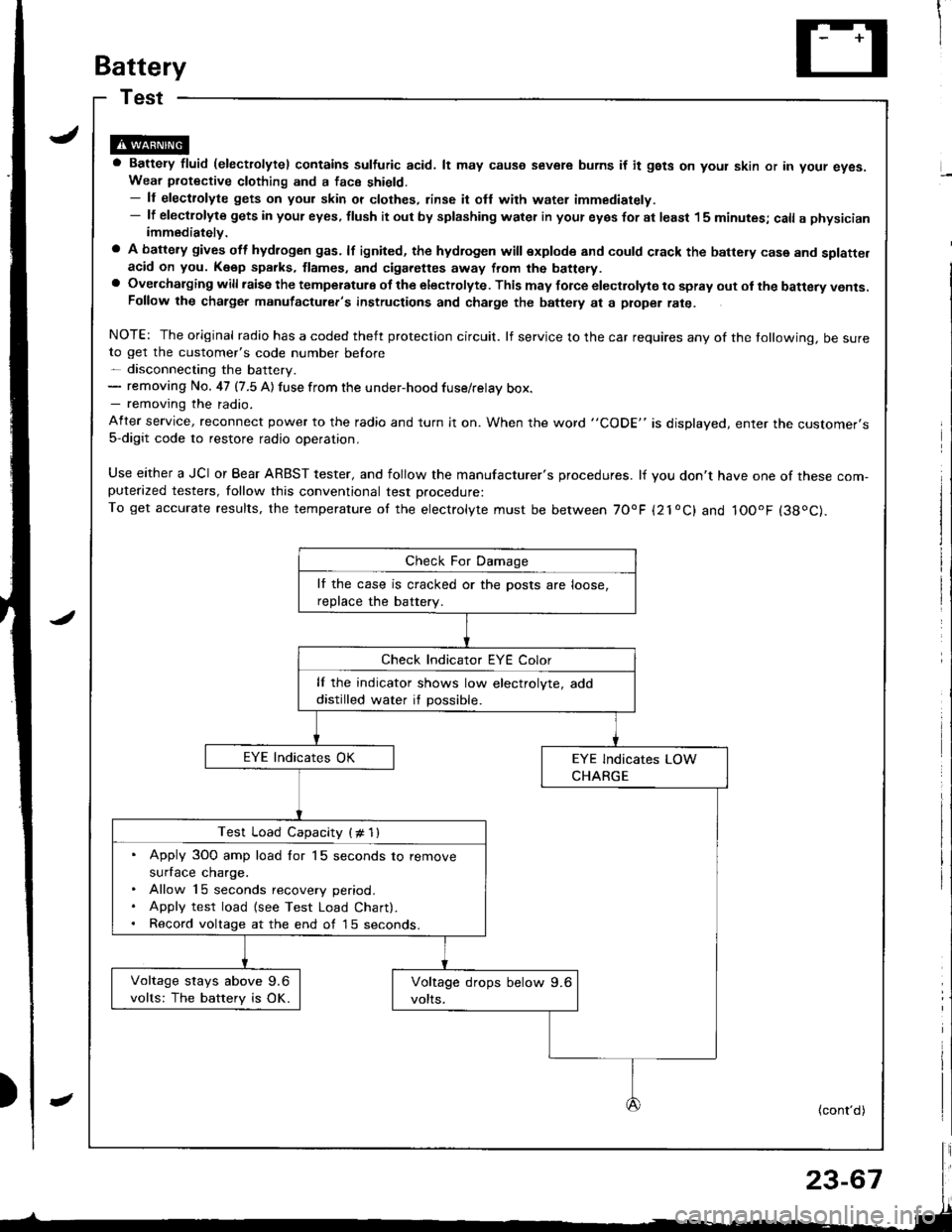
Battery
a Battery fluid (electrolytel contains sulfuric acid. lt may causo severe burns if it gsts on yout skin or in your eyes.Wear piotective clothing and a face shield.- ll electrolyte gets on your skin or clothes, rinse it ofl with water immediately.- lf electlolyte gets in your eyes, tlush it out by splashing water in your eyes for at least 15 minutes; call a physicianimmediately.
a A battery gives off hydlogen gas. lf ignited, the hydrogen will explode and could crack the battery case and splatte.acid on you. K6ep sparks, flames, and cigarettes away from the battery.a Overchalging will raisc the temperatulg of the electrolyte. This may force electrolyte to spray out ol the battery vents.Follow the chatge. manutacturer's instructions and charge the baftely at a ptope. rate.
NOTE: The original radio has a coded theft protection circuit. lf service to the car requires any of the tollowing, be sureto get the customer's code number before- disconnecting the battery.- removing No. 47 (7.5 A) fuse from the under-hood fuse/relay box.- removing the radio.
After service, reconnect power to the radio and turn it on. When the word "CODE" is displayed, enter tne customer's5-digit code to restore radio operation,
Use either a JCI or Bear ARBST tester, and follow the manufacturer's procedures. lf you don't have one of these com-puterazed testers, follow this conventional test Drocedure:To get accurate results, the temperature of the electrolyte must be between 70'F {21oC} and IOOoF (38oC).
lf the case is cracked or the posts are loose,
reDlace the batterv.
lf the indicator shows low electrolyte, add
distilled water if possible.
Test Load Capacity (# 1l
. Apply 3O0 amp load for 15 seconds to remove
surface charge.. Allow 15 seconds recovery period.. Apply test load {see Test Load Chart).. Record voltage at the end of l5 seconds.
Voltage stays above 9.6
volts: The battery is OK.
(cont'd)
Page 1390 of 1681
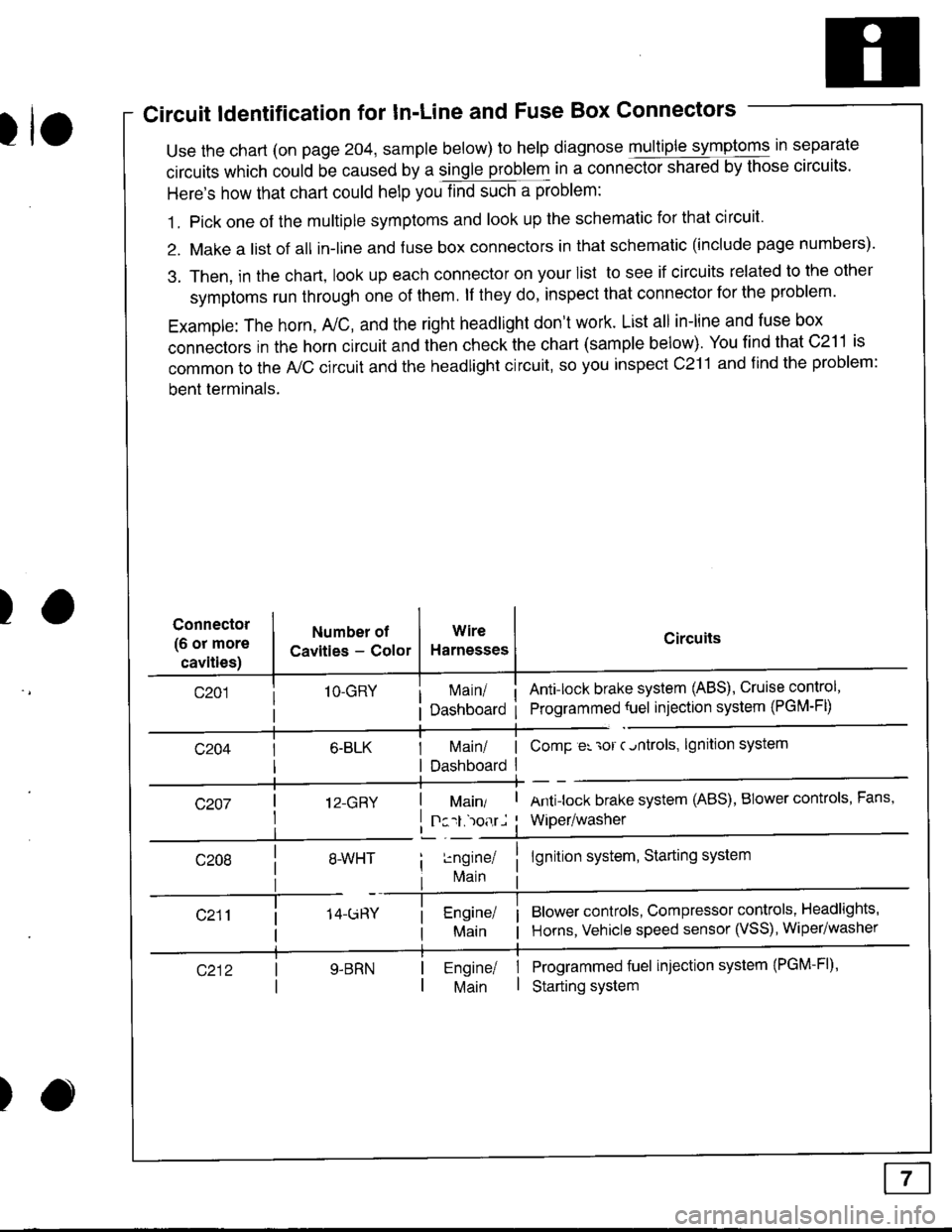
Circuit ldentification for In'Line and Fuse Box Connectors
tuse the chart (on page 204, sample below) to help diagnose multiple symptoms in separate
circuits which could be caused by a single problem in a connect,oishared by those circuits'
Here's how that chart could help you find such a problem:
1. Pick one of the multiple symptoms and look up the schematic for that circuit'
2. Make a list of all in-lrne and fuse box connectors in that schematic (include page numbers).
3. Then, in the chart, look up each connector on your list to see if circuits related to the other
symptoms run through one of them. lf they do, inspect that connector for the problem.
Example: The horn, A,/C, and the right headlight don't work. List all in-line and fuse box
connectors in the horn circuit and then check the chart (sample below). You find that C211 is
common to the A,/C circuit and the headlight circuit, so you inspect c211 and find the problem:
bent terminals.
)Connector
(6 or more
cavities)
Numbel of
Cavities - Color
1O-GRY
I 12-GRY
I
Wire
Harnesses
I Main/ | ComP er 'ror c.ntrols,
I Dashboard I
Circuits
Ant!lock brake system (ABS), Cruise control,
Programmed {uel injection system (PGM-FD
!ngrnei
lvlain
lgnition system
Antilock brake system (ABS), BIower controls, Fans,
Wiper/washer
lgnition system, Starting system
Blower controls, Compressor controls, Headlights'
Horns, Vehicle speed sensor (VSS), Wiper/washer
Programmed fuel injection system (PGM-Fl)'
Starting system
Engine/ |Main I
)
Page 1632 of 1681
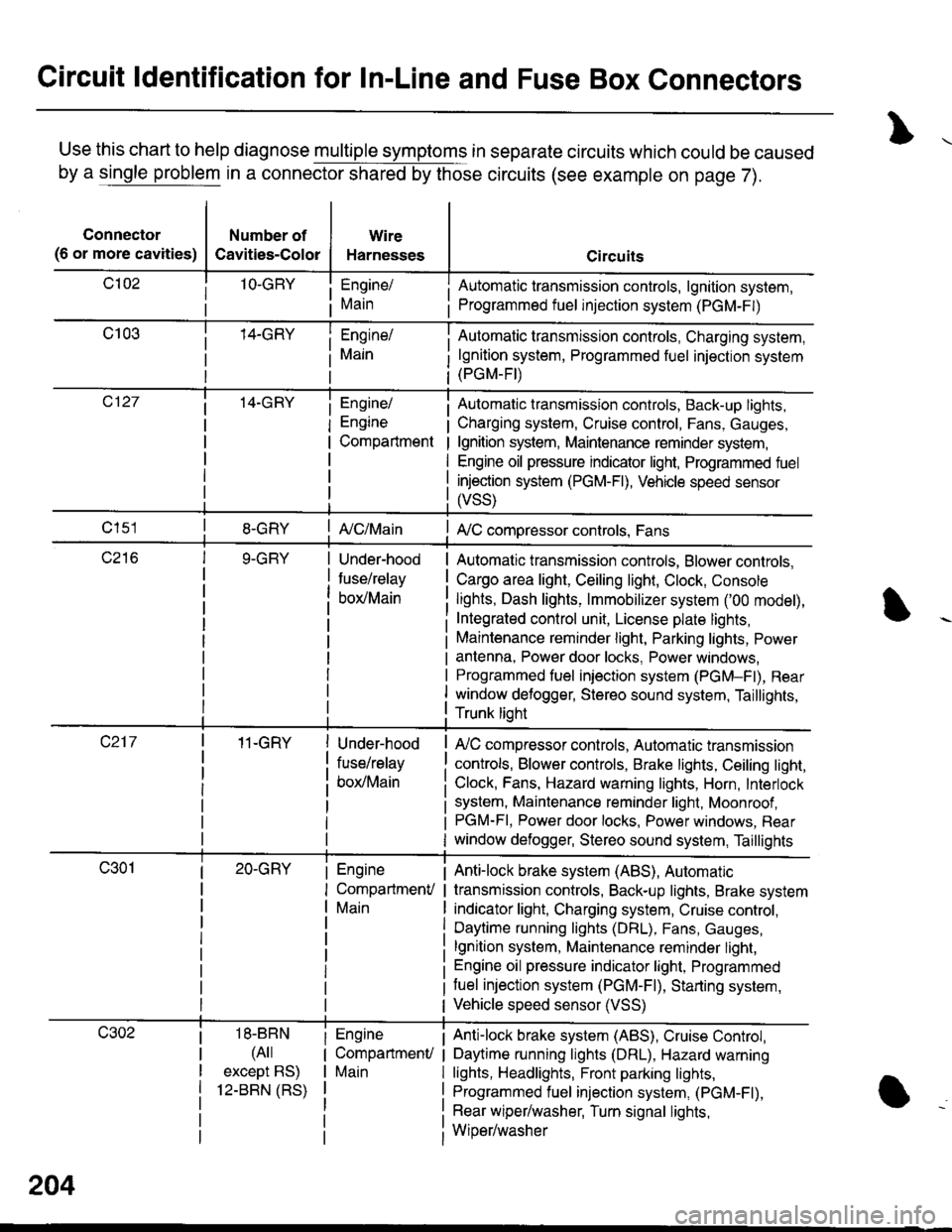
Circuit ldentification for In-Line and Fuse Box Connectors
Use this chart to help diagnose multiple symptoms in separate circuits which could be caused
by a single problem in a connector shared by those circuits (see example on page 7).
Connector
(6 or more cavities)
Number of
Cavities-Color
Wire
Harnesses
Engine/
Main
Engine/
Engine
Compartment
I Automatic transmission controls, lgnition system,
i Programmed fuel injection system (PGM-F|)
Automatic transmission controls, Charging system,
lgnition system, Programmed fuel injection system(PGM-FI)
Automatic transmission controls, Back-up lights,
Charging system, Cruise control, Fans, Gauges,
lgnition system, Maintenance reminder system,
Engine oil pressure indicator light, Programmed fuel
injection system (PGM-Fl), Vehicle speed sensor
ffss)
| {c/Main! A,/C compressor controls, Fans
Under-hood
fuse/relay
box/Main
Automatic transmission controls, Blower controls,
Cargo area light, Ceiling light, Clock, Console
lights, Dash lights, lmmobilizer system ('00 model),
Integrated control unit, License plate lights,
Maintenance reminder light, Parking lights, Power
antenna, Power door locks, Power windows,
Programmed fuel iniection system (PGM-Fl), Rear
window defogger, Stereo sound system, Taillights,
Trunk lioht
11-GRY
18-BBN
(4il
except BS)
12-BBN (RS)
Under-hood
fuse/relay
box/Main
Engine
CompartmenV
Main
Engine
CompartmenU
Main
lr,/C compressor controls, Automatic transmission
controls, Blower controls, Brake lights, Ceiling light,
Clock, Fans, Hazard warning lights, Horn, Interlock
system, Maintenance reminder light, Moonroof ,PGM-FI, Power door locks, Power windows, Rear
window defogger, Stereo sound system, Taillights
Anti-lock brake system (ABS), Automatic
transmission controls, Back-up lights, Brake system
indicator light, Charging system, Cruise control,
Daytime running lights (DRL), Fans, Gauges,
lgnition system, Maintenance reminder light,
Engine oil pressure indicator light, Programmed
tuel injection system (PGM-F|), Starting system,
Vehicle speed sensor (VSS)
Anti-lock brake system (ABS), Cruise Conkol,
Daytime running lights (DRL), Hazard warning
lights, Headlights, Front parking lights,
Programmed fuel injection system, (PGM-Fl),
Rear wiper/washer, Turn signal lights,
Wiper/washer
204