set clock HONDA INTEGRA 1998 4.G User Guide
[x] Cancel search | Manufacturer: HONDA, Model Year: 1998, Model line: INTEGRA, Model: HONDA INTEGRA 1998 4.GPages: 1681, PDF Size: 54.22 MB
Page 1263 of 1681
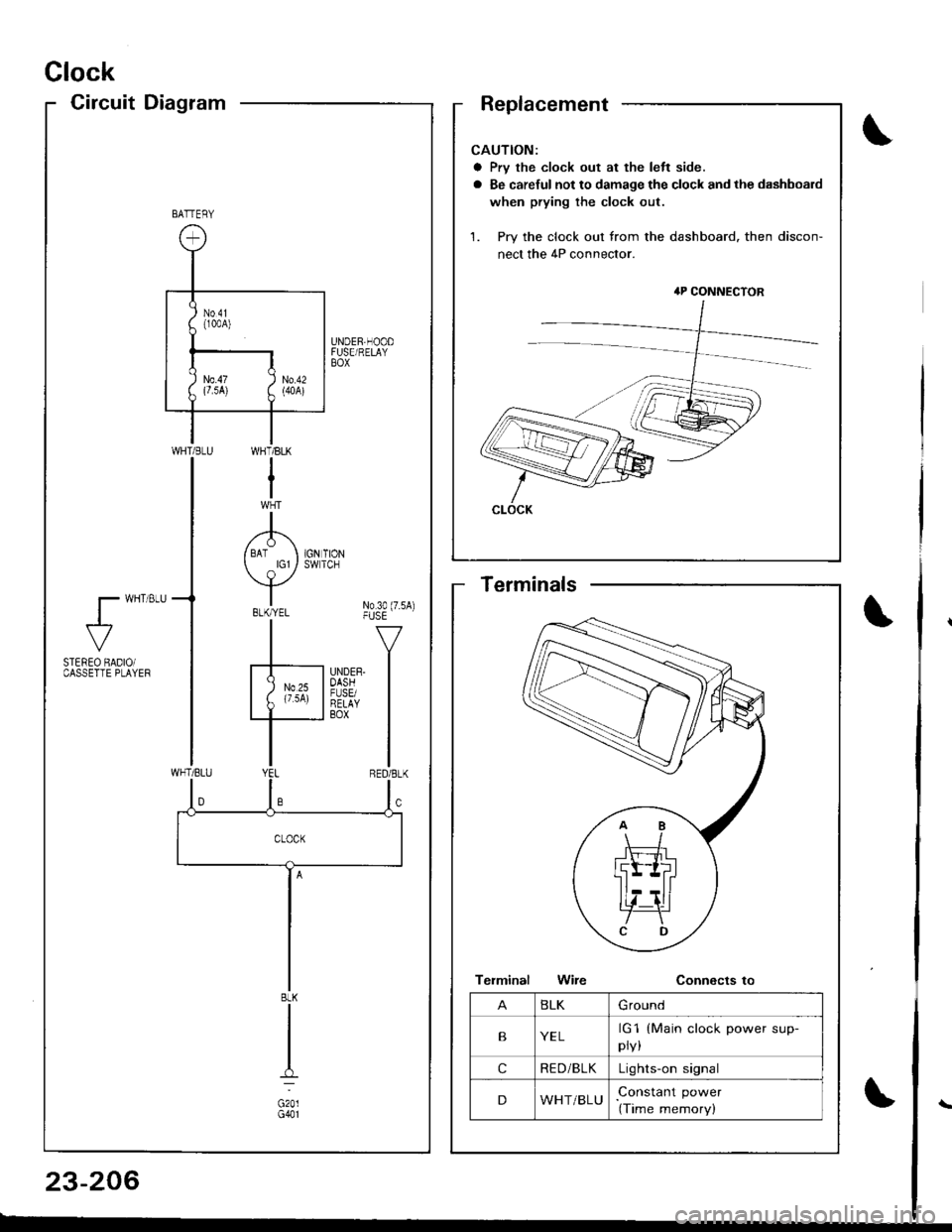
Clock
CircuitDiagram
CAUTION:
a Prv the clock out at the left side.
a Be careful not to damage the clock and the dashboard
when prying the clock out.
1. Pry the clock out from the dashboard. then discon-
nect the 4P connector.
4P CONNECTOR
CLOCK
BATTERY
UNDER,HOODFUSE/RELAYBOX
WI-]T/BLK
I
A/ BAT I 1GN TION
Y*"t No3o(7.sA)-|" -v
F'nrrn l
I
WHT/BLU
l- wHT 8LU
al-
STEREO BADIOiCASSETTE PLAYEF
BLK
G201G401
BLKGround
BYELrG1
pry,
(Main clock power sup-
cRE D/BLKLights-on signal
DWHT/BLUConstant power
(Time memory)
Terminals
23-206
Page 1378 of 1681
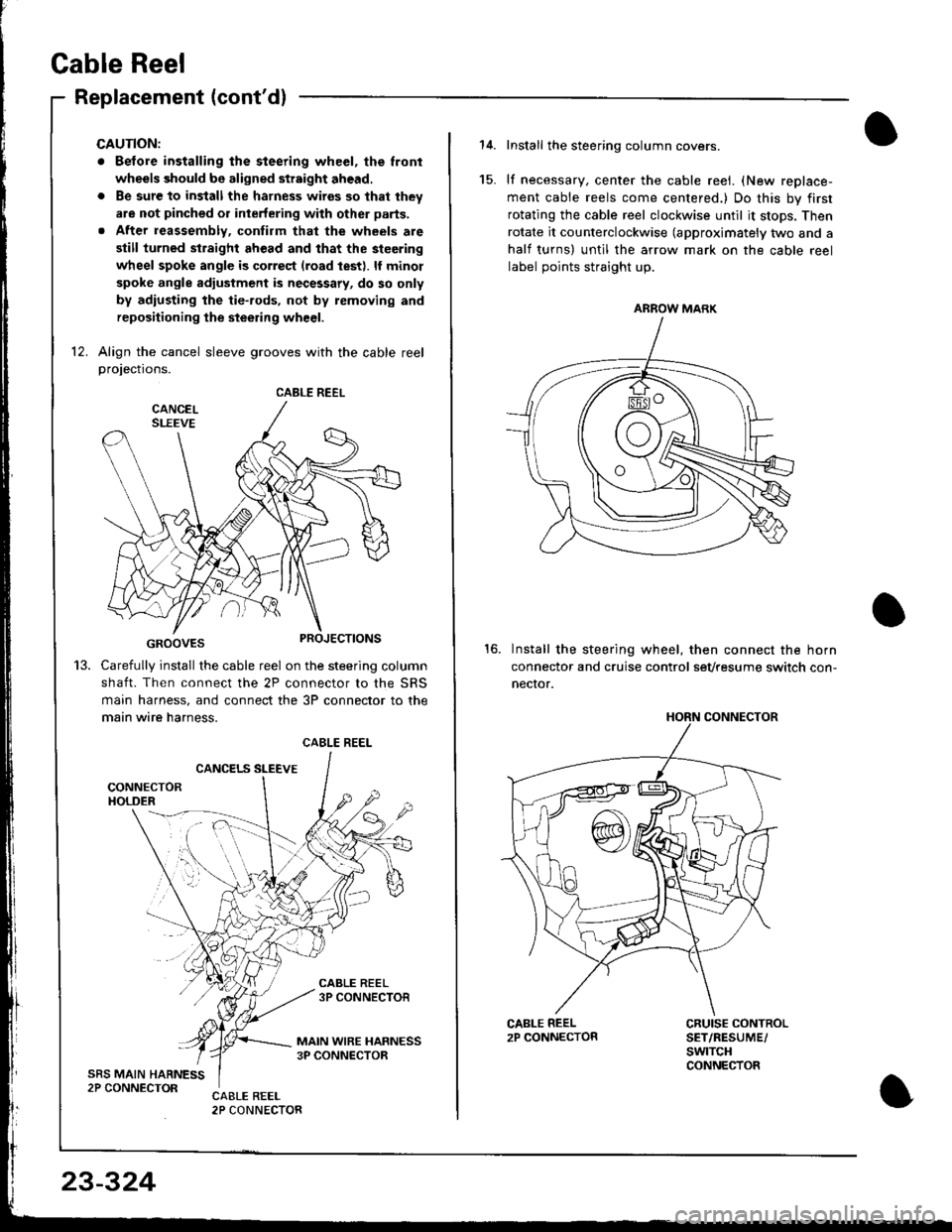
Cable Reel
Replacement (cont'dl
CAUTION:
. Before installing the steering wheel, the lront
wheels should be aligned str8ight ahead.
. Be sure to install the harness wires so that they
are not pinched or interfering with other parts.
. After reassembly, confirm thal the wheels are
slill turned str8ight ahead and that the steering
wheel spoke angle is correst (road test). lf minol
spoke angle adjustment is necessary, do so only
by adiusting the tie-.ods, not by removing and
repositioning the steering wheel.
12. Align the cancel sleeve grooves with the cable reelprojections.
GROOVES
Carefully install the cable reel on the steering column
shaft. Then connect the 2P connector to the SRS
main harness, and connect the 3P connector to the
main wire harness.
CANCELS SLEEVE
CABLE REEL
13.
CABLE REEL
23-324
Install the steering column covers.
lf necessary, center the cable reei. (New replace-
ment cable reels come centered.) Do this by first
rotating the cable reel clockwise until it stops. Then
rotate it counterclockwise (approximately two and a
half turns) untll the arrow mark on the cable reel
label points straight up.
Install the steering wheel, then connect the horn
connector and cruise control sevtesume switch con-
necror.
15.
16.
CRUISE CONTROLSET/RESUME/swtTcHCONNECTOR
ARROW MARK
HORN CONNECTOR
Page 1402 of 1681
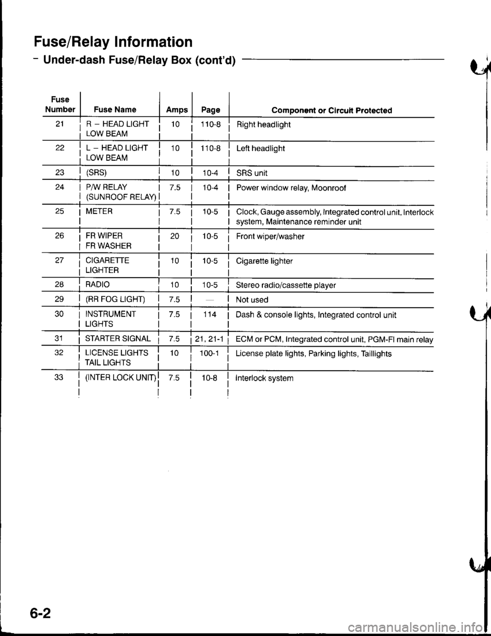
FuserRelay I nformation
- Under-dash Fuse/Relay Box (cont'd)
Fuse
Number
i R - HEAD LTGHT ii LOWBEAM i
Fuse NameAmpsPageComponent or Clrcull Protected
10 ii Right headlight
! L _ HEAD LIGHT I
I row eenu I
10 i110-8Left headlight
(sRs)I roSRS unit
24 I P/IV RELAY IPower window relav. Moonroof
l(suNRooFBELA!l
7.5 I 10-4 |
tl
25 | METER | 7.5 | 10-5 |
rttl
Clock, Gauge assembly, Integrated control unit, Interlock
system, Maintenance reminder unit
Front wiper/washer26 i FR W|PER
I FR WASHEB
27 | crcnnerre
i LTGHTER
28 i RApro i10 i
Cigarette lighter
10-s iStereo radio/cassette player
30 I INSTRUMENT
I LIGHTS
2e | (RR Foc LtcHT) | z.s !
| 7.5 |
tl
3'1 i STARTER STGNAL21,21-1 1
32 i LTCENSE LtcHrS Ii TAIL LIGHTS ii 1001 i
| (rNrER LocK uNrr)l
II
114 | Dash & console lights, Integrated control unit
ECM or PCM, Integrated control unit, PGM-FI main relay
License plate lights, Parking lights, Taillights
Interlock system
6-2
Page 1404 of 1681
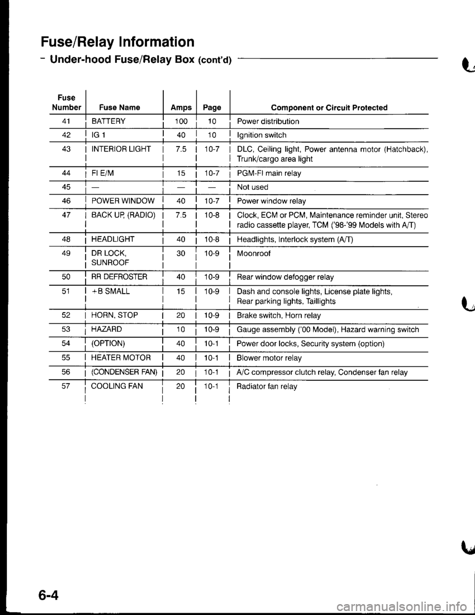
Fuse/Relay I nformation
- Under-hood Fuse/Relay Box (cont'd)
Fuse
NumberFuse NameAmpsPage
BATTERY
I INTERIOR LIGHT
I
1 7.5 110-7 I
I
Component or Circuil Protected
Power distribution
lgnition switch
DLC, Ceiling light, Power antenna motor (Hatchback),
Trunk/cargo area light
47
I Fl E/lvl
POWER WINDOW
I BACK UP (RADTO)
I
15 | 1 0-7 I PGM-FI main relay
Not used
Power window relay
Clock, ECM or PCM, Maintenance reminder unit, Stereo
radio cassette player, TCM ('98-'99 Models with A'/T)
7.5 |10-8
I HEADLIGHT| 40 | 10-8 | Headlights, Interlock system (A/T)
49i DR LOCK,
i suNRooF
10-9 i Moonroof
I
I RR DEFROSTER
+ B SMALL
I Rear window detogger relay
I Dash and console lights, License plate lights,
I Rear parking lights, Taillights
I HORN, STOP
i HAZARD
10-9 | Brake switch, Horn relay
i Gauge assembly ('00 Model), Hazard warning switch
40 | to t I Power door locks, Security system (option)
I HEATER MOTOR II t 0-1I Blower motor relay
20 I 10-1 ; A,/C compressor clutch relay, Condenser fan relay
i Radiator fan relay1 0-1
6-4
Page 1413 of 1681
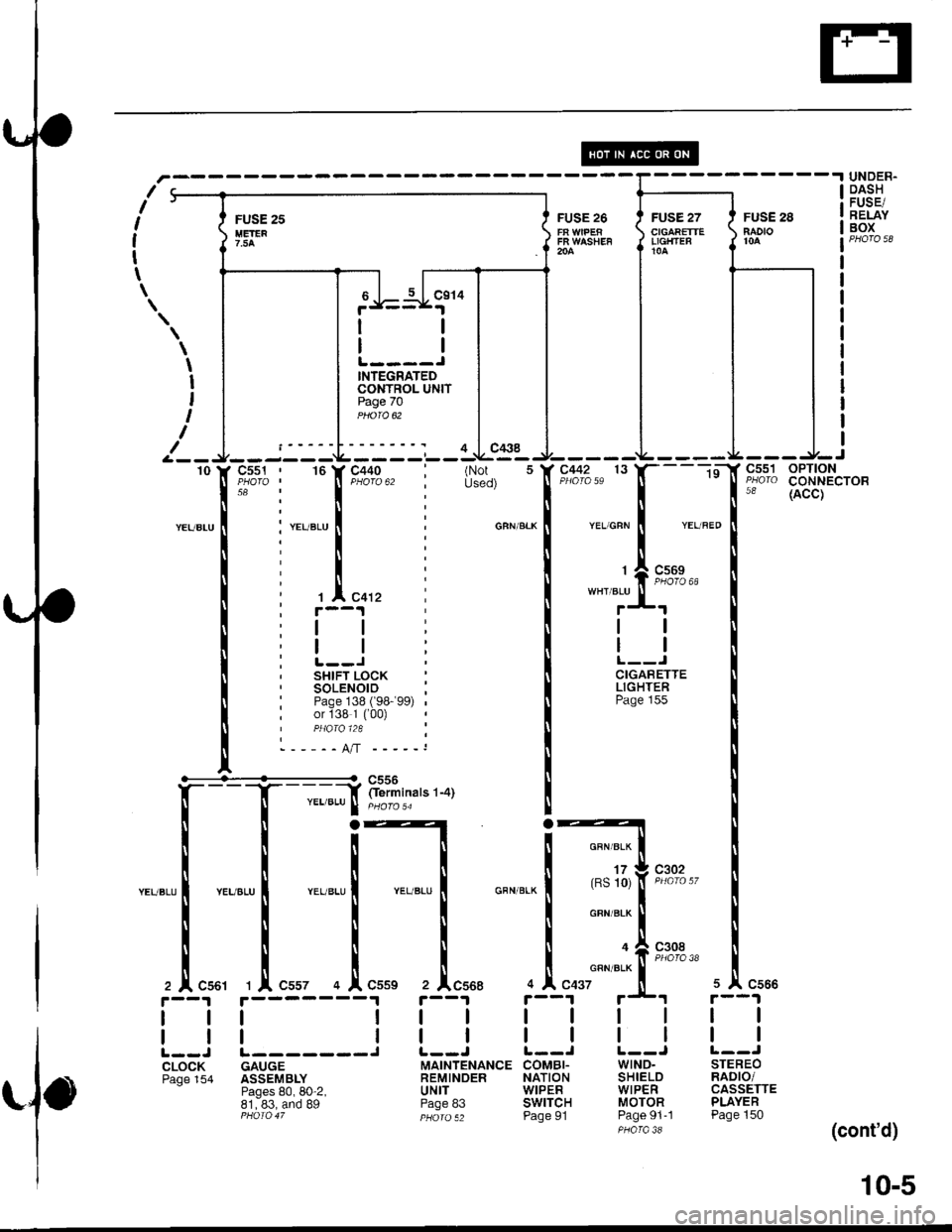
UNDER.DASHFUSE/RELAYBOXFUSE 25IIETER?.5A
FUSE 26
FR WASHEF204
\
I
I
t
I
I
INTEGRATEDCONTROL UNITPage 70
- - -Y iliirinars r-arYEL/BLU I pHoro,4
't0--i:--L
-
--'-r--
,c;% : " lf "tio$, ir':ii
i 'r.u".u | :
:ii
il;
i 'I"0,, I, r--1
:ll:
i !.--l iI SHIFT LOCK, SoLENOIO ;: Paqe 13B ( 98-99) ,; or 138 1 ('00)I PHQ|O 124 ;------o,n -----,
Czt38
t-
":-[ "::]
*-' 33r'$$'o"
-"'",,*j*"
I
i'sn+.1* !Pase 1ss
I
I
,T'*' I
-u.,*""1t-**" ,Iu*c55t 1|' Cs57 4
I
IL--J L-------JCLOCK GAUGEPage 154 ASSEMBLYPages 80, 80-2,81, 83, and 89PHOIO 47
(Not 5Used)
GBN/BLK
?
I
I
c559.l
I
I
1 r-1 r--1
I
Il1
WIND.SHIELDWIPERMOTORPage 91-1
t--J L--JMAINTENANCE COMBI.REMINDER NATIONUNIT WIPERPage 83 SWITCHpHoro s2 Page 91
STEREORADIO/CASSETTEPLAYERPage 150
(cont'd)
10-5
Page 1416 of 1681
![HONDA INTEGRA 1998 4.G User Guide Power Distribution
- From Fuses to Relays and Components (contd)
rll
FUSE 48 \HEAruCHT \{la \
II-------Jc216c217
::]:I
-..
3
ir
:l
:!, I tFUSE20, : (BUNNTNG, I I u_qHrc)
LJ___
. - All except US HONDA INTEGRA 1998 4.G User Guide Power Distribution
- From Fuses to Relays and Components (contd)
rll
FUSE 48 \HEAruCHT \{la \
II-------Jc216c217
::]:I
-..
3
ir
:l
:!, I tFUSE20, : (BUNNTNG, I I u_qHrc)
LJ___
. - All except US](/img/13/6069/w960_6069-1415.png)
Power Distribution
- From Fuses to Relays and Components (cont'd)
r'l'l
FUSE 48 \HEAruCHT \{la \
II-------Jc216c217
::]:I
-'..
'3
ir
:l
:!, I tFUSE20, : (BUNNTNG, I I u_qHrc)
'LJ___
. - All except USA RS - r
SECURITYSYSTEMCONNECTOR(oPTroN)
' BLU
,SECURITY SECURITY :.SYSTEM SYSTEM: CONNECTOR CONNECTOR ,
, (oPTroN) (oPTtoN) :I PHA|A 124 PHA|A 48 ,
UNDER-DASHFUSE/RELAYBOX
il
:l
i_J_
li:
tl
i [--., COMBI.. NATION
: LIGHT; swrTcF, Page 101
-- 18JF#
T
tn"r,o"" I
i
'*9,'ot,
"*r,o"" I
rrr
1l
tl
STEERINGLOCKPage 138('98- 99) or138,1 f00)
--'- Nr --
c452 wHr/BLU
'00 Model
: 16 r--
WHT/BLU
I(RS 7)
WHT/ALU
I Y€L
' 2 lt c415
i i--t't I
:l I
i olwrme, RUNNING, LIGHTSI CONTROL
: uNrT, Page 1'10-9
:. - . Canada
'98-'�99
N,4odels
BLU
4 A C566
lt
ll
STEREO
Page
4 A C56(
lt
ll
STEREORADIO/CASSETTEPLAYERPaqe 150
ztlr7l!Ntl
ittaru f wnlalu I wrrier-u I
o,[ "uu' ,,, .!, "ou, ,o .!, "oo,r--1r--.|r--1
trtttl
tttttlL--J t--J t--JCLOCK POWERTRAIN ENGINEPage 154 or ENGINE CONTROLCONTROL MODULEMOOULE (ECM)(PCM or ECM) Paqe 23Pages 24 pr6ro ,,and 39-4PHO|O 14A
1 A C568
tl
tl
MAINTENANCEREMINDERUNITPage 83
10-8
Page 1614 of 1681
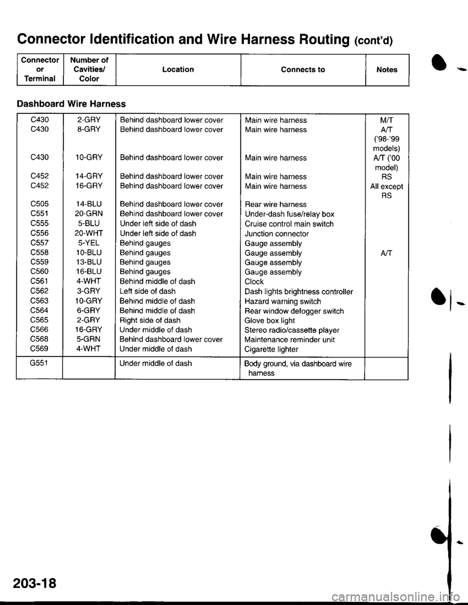
Connector ldentification and Wire Harness Routing (conrd)
Connector
or
Terminal
Number of
Cavities/
Color
LocationConnects toNotes
Dashboard Wire Harness
c430
c430
c430
c452
c452
UCUC
lJcc I
uccc
trCSO
c557
c558
uccv
c560
c561
c562
UCOJ
uco4
UJb5
ucoo
ucoo
UCOY
2-GRY
8-GRY
1O.GRY
14-GRY
16.GRY
14.BLU
2O.GRN
5-BLU
2O-WHT
5-YEL
1O.BLU
13-BLU
16-8LU
4.WHT
3-GRY
1O-GRY
6-GRY
2-GRY
16.GBY
5-GRN
4-WHT
Behind dashboard lower cover
Behind dashboard lower cover
Behind dashboard lower cover
Behind dashboard lower cover
Behind dashboard lower cover
Behind dashboard lower cover
Behind dashboard lower cover
Under left side of dash
Under left side of dash
Behind gauges
Behind gauges
Behind gauges
Behind gauges
Behind middle ot dash
Left side ol dash
Behind middle of dash
Behind middle of dash
Right side of dash
Under middle of dash
Behind dashboard lower cover
Under middle of dash
Main wire harness
Main wire harness
Maih wire harness
Main wire harness
Main wire harness
Rear wire harness
Under-dash fuse/relay box
Cruise control main switch
Junction connector
Gauge assembly
Gauge assembly
Gauge assembly
Gauge assembly
Clock
Dash lights brightness controller
Hazard warning switch
Rear window defogger switch
Glove box light
Stereo radio/cassette player
Maintenance reminder unit
Cigarette lighter
M/T
Arl
/'oR-'oo
models)
A/T (00
model)
RS
All except
RS
Aft
G551Under middle of dashBody ground, via dashboard wire
namess
Page 1654 of 1681
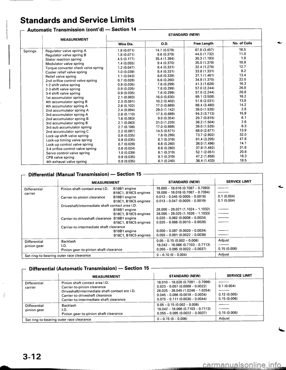
MFASIIREMENTSTANDARD (NEW}
Wire Dia.o.D.Free LengthNo. of Goils
SpringsRegulator valve spring ARegulator valve spring BStator reaction sPringModulator valve springTorque converter check valve springCooler relief valve springRelief valve spring2nd orifice control valve spring1-2 shift valve spring2-3 shift valve spring3-4 shift valve spring1st accumulator spring4th accumulator spring B4th accumulator spring A2nd accumulator spring A3rd accumulator spring A2nd accumulator spring B3rd accumulator spring B3rd sub accumulator spring2nd accumulator spring CLock-up shift valve springLock-up timing valve springLock-up control valve spring3-4 orifice control valve springServo control valve springCPB valve spring4th exhaust valve spring
1.8 (0.071)
1.8 (0.071)
4.5 rc.177].1.4 (0.05s)
1.2 10.047l.1.0 (0.039)
1.1 (0.043)
0.7 (0.0281
0.9 (0.035)
0.9 (0.035)
0.9 (0.035)
2.1 (0.083)
2.3 (0.091)
2.6 (0.102)
2.4 (0.094)
2.8 (0.110)
1.6 (0.063)
2.1 (0.083)
2.7 (0.106)
2.2 l0.o87l0.9 (0.035)
0.9 (0.035)
0.7 (0.028)
0.6 (0.024)
1.0 (0.039)
0.9 (0.0351
0.9 (0.035)
14.7 (0.5791
9.6 (0.378)
35.4 (1 .394)9.4 (0.370)
8.4 (0.331)
8.4 (0.331)
8.6 (0.339)
6.6 (0.260)
7.6 (0.299)
7.6 (0.299)
7.6 (0.299)
16.0 (0.630)
10.2 rc.402117.0 (0.669)
29.0 11.142117.5 (0.689)
9.0 (0.354)
31.0 (1 .220)17.0 (0.669)
14.5 (0.571)
7.6 (0.299)
8.1 (0.319)
6.6 (0.260)
6.6 (0.260)
8.1 (0.319)
8.1 (0.319)
6.1 (0.240)
87.8 (3.457)
44.0 (1.732\
30.3 (1.193)
35.0 (1.378)
32.4 (1.2761.
33.8 (1.331)
37.1 (1.461)
34.8 (1.370)
41.3 (1.626)
57.0 12.244157.0 12.244].89.1 (3.508)
s1.6 (2.0311
88.4 (3.480)
39.0 (1 .53s)94.3 (3.713)
20.7 (0.815)
38.2 (1.504)
39.0 (1.535)
68.0 (2.677)
73.7 (2.9021
81.4 (3.205)
38.0 (1.496)
37.9 (1.492)
52.1 (2.0511
47.2 (1 .858)36.4 (1.433)
16.51 1.01.910.912.78.213.422.01A ?
26.826.8't6.2
13.814.2z.J15.9o. l2.66.313.932.O47.814.1?1 A
20.8ttJ.JI v.5
Standards and Service Limits
Automatic Transmission (cont'd) - Section 14
Differential (Manual Transmission) - Section 15
Differential (Automatic Transmission) - Section 15
ilt5stlrrr, - 4,
MEASUREMENTSTANDARD (NEW}SERVICE LIMIT
Differentialca rnerPinion shaft contact area l.D. 81881 engineB18C1, 818C5 engines
Carrier-to-pinionclearance Bl88lengine818C1, 818C5 enginesDriveshafVintermediate shaft contact area l.D.81881 engine818C1. 818C5 engines
Carrier-to-driveshaft clearance 81881 engine818C1, 818C5 engines
Carrier-to-intermediate shaft clea rance81881 engine818C1, 818C5 engines
18.000 - 18.016 (0.7087 - 0.7093)18.000 - 18.018 (0.7087 - 0.7094)0.013 - 0.045 (0.0005 - 0.0018)0.013 - 0.047 (0.0005 - 0.0019)
28.000 - 28.021 11.1024 - 1.1032].28.005 - 28.025 l1 .'�t026 - 1 .1 033)
0.020 - 0.062 (0.0008 - 0.0024)0.025 - 0.066 (0.0010 - 0.00261
0.050 - 0.087 (0.0020 - 0.0034)0.055 - 0.091 (0.0022 - 0.0036)
- toooot0.1 (0.004)
Differentialpinion gearBacklasht.D.Pinion gear-to-pinion shaft clearance
0.05 - 0.15 (0.002 - 0.006)18.042 - 18.066 (0.7103 - 0.71 1 3)0.055 - 0.095 (0.0022 - 0.0037)
Adjust
0.15 (0.006)
Set ring-to-bearing)uter race clearance0 - 0.10 (0 - 0.004)Adjust
nsmlssaonl - Sectton
MEASUREMENTSERVICE LIMITSTANDARD (NEW}
Differentialca rrierPinion shaft contact area l.D.Carrier-to-pinion clearanceDriveshaft/i ntermediate shaft contact are l.D.
Carrier-to-driveshaft clearanceCarrier-to-intermediate shaft clearance
18.010 - 18.028 (0.7091 - 0.7098)0.023 - 0.057 (0.0009 - 0.0022)26.025 - 26.045 11.0246 - 1.02541
0.045 - 0.086 (0.0018 - 0.0034)0.075 - 0.1 11 (0.0030 - 0.0044)
0.1 (0.004)
0.12 (0.005)
0.15 (0.006)
Differentialpinion gearBacklasht.D.Pinion gear-to-pinion shaft clearance
0.05 - 0.15 (0.002 - 0.006)18.042 - 18.066 (0.7 103 - 0.71 1 3)0.055 - 0.095 (0.0022 - 0.0037)0.15 (0.006)
Set ring-to-bearing outer race clearance0 - 0.15 (0 - 0.006)Adiust
uL-
3-12
(-