diagram HONDA INTEGRA 1998 4.G Workshop Manual
[x] Cancel search | Manufacturer: HONDA, Model Year: 1998, Model line: INTEGRA, Model: HONDA INTEGRA 1998 4.GPages: 1681, PDF Size: 54.22 MB
Page 418 of 1681
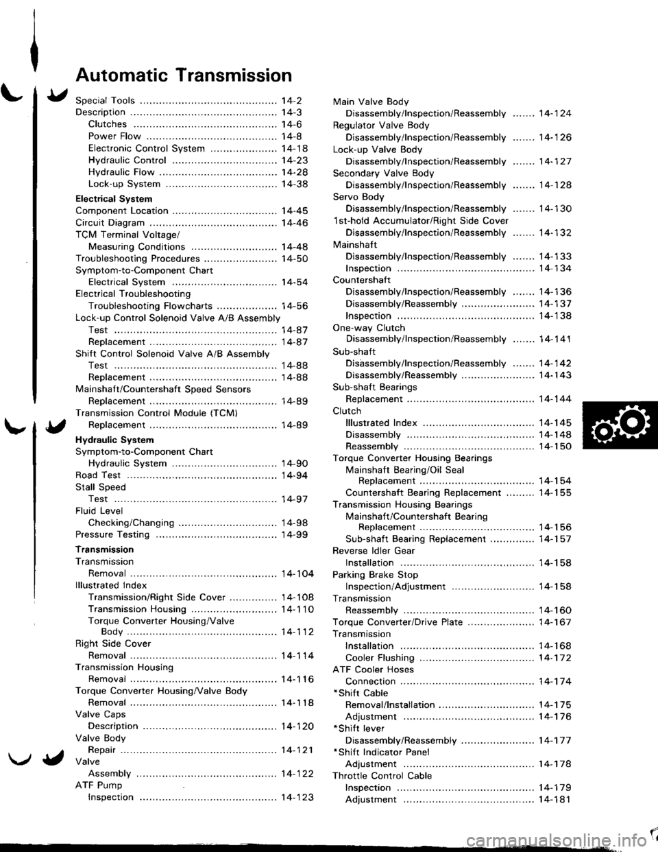
Automatic Transmission
Special Tools ................ '14-2
Descraption .................... 14-3
Clutches ............ ...... 14-6
Power Flow ..,........... 14-8
Electronic Control System ..................... 1 4-1 8
Hydraulic Control ...... 14-23
Hydraulic Flow .........- 14-28
Lock-up System ........ 14-38
Electrical System
Component Location -................................ 1 4-45
Circuit Diagram ............. 14-46
TCM Terminal Voltage/
Measuring Conditions ......,.................... 1 4-48
Troubleshooting Procedures .. . ... ........ ...... ... 14-50
Symptom-to-Component Chart
Electrical System ...... 14-54
Electrical Troubleshooting
Troubleshooting Flowcharts .......... ... ...,.. 14-56
Lock-up Control Solenoid Valve A/B Assembly
Test .................. ...... 14-A7
Replacement ............. 14-a7
Shilt Control Solenoid Valve A/B Assembly
Test .................. ...... '14-88
Replacement .,..,........ 14-88
lvlainshaf t/Countershaft Speed Sensors
Replacement ....-......,. 14-89
Transmission Control Module (TCM)
Replacement ............. 14-89
Hydraulic System
Symptom-to-Component Chart
Hydraulic System ...... 14-90
Road Test ,................... 14-94
Stall Speed
Test .................. ...... 14-97
Fluid Level
Checking/Changing .... 14-98
Pressure Testing ........... 14-99
Transmission
Transmission
Removal ............. ...... 14-10�4
lllustrated lndex
Transmission/Right Side Cover ............... 1 4-1 08
Transmission Housin9 ................,..,....... 1 4-1'1 O
Torque Converter Housing/ValveBody .................. .. 14-112
Right Side Cover
Removal ............. ...... 14-114
Transmission Housing
Removal ............. ...... 14-1 l6
Torque Converter Housing/Valve Body
Removal ............. ...... l4-1 18
Valve Caps
Description ...........-... 14-120
Valve Body
Repair ................ ...... 14-12'l
Valve
Assembly
ATF Pump
Inspeclton
Main Valve Body
Disassembly/lnspection/Reassembly
Regulator Valve Body
Disassembly/lnspection/Reassembly
Lock-up Valve Body
Disassembly/lnspection/Reassembly
Secondary Valve Body
Disassembly/lnspection/Reassembly
Servo Body
....... 14-124
....... 14-126
....... 14-127
....... 14 124
Disassembly/lnspection/Reassembly .......
1st-hold Accumulator/Right Side Cover
Disassembly/lnspection/Reassembly .......
Mainsha{t
14-130
14-132
Disassembly/lnspection/Reassembly ....... 14-133
Inspection ................. 14-134
Countershaft
Disassembly/lnspection/Reassembly,..,.., l4-136
Disassembly/Reassembly ..,...,..,.........,,.. 1 4-1 37
Inspection ......,...,..,... 14-138
One-way Clutch
Disassembly/lnspection/Reassembly ....,.. 14-141
Sub-shaft
Disassembly/lnspection/Reassembly ...,,..'14-142
Disassembly/Reassembly ....................... 1 4- l 43
Sub-shaft Bearings
Replacement ,..,,.,,..,.. 14-144
Clutch
lllustrated Index ................................... I 4-1 45
Disassembly ............. 14-144
Reassembly .............. 14-150
Torque Converter Housing Bearings
Mainshaft Bearing/Oil Seal
Replacement ......... 14-154
Countershaft Bearing Replacement ......... 1 4- 1 55
Transmission Housing Bearings
Mainshaft/Countershaft BearingReplacement ......,.. 14-'156
Sub-shaft Bearing Replacement .,............ 1 4-1 57
Reverse ldler Gear
Installation .........-..... 14-158
Parking Brake Stop
Inspection/Adjustment .......................... 1 4-1 58
Transmission
Reassembly .............. 14-160
Torque Converler/Drive Plate ..............,.,,.,, 1 4-1 67
Transmission
Installation ............... 14-168
Cooler Flushing ......... 14-172
ATF Cooler Hoses
Connection ,..,,,....,,.,, '14-'174
*shift cable
Removal/lnstallation . . .. .... ... .... ... .... .. . ... .. 14-'l75
Adjustment ,..,...,,,,.,, 14-'116*Shilt lever
Disassembly/Reassembly ....................... 1 4-'17 7'Shift Indicator Panel
Adjustment .............. 14-178
\l
)g
Page 439 of 1681
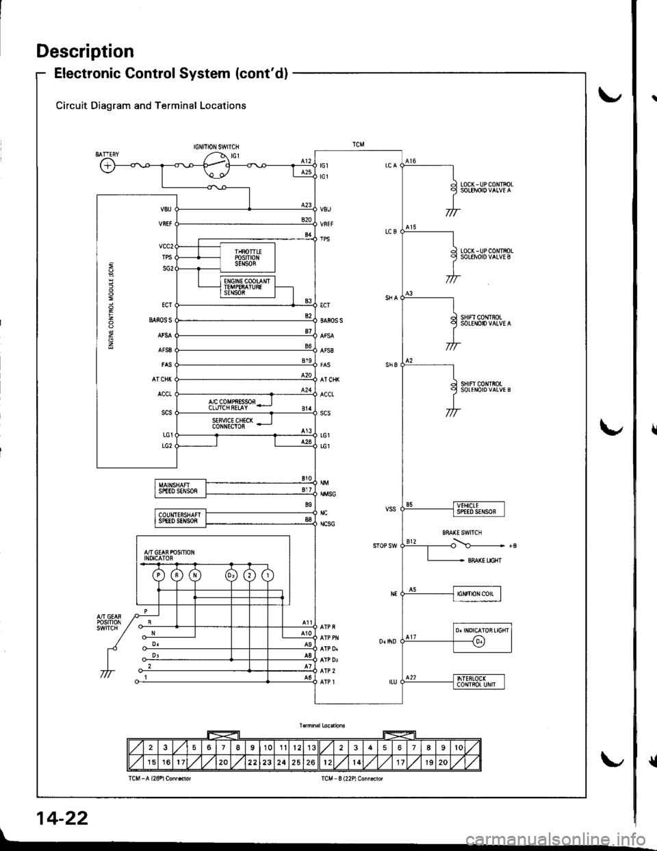
Description
Electronic Control System (cont'd)
Circuit Diagram and Terminal Locations
IGNITIONSWITCH
LOC(-UPCONTFOL
LOCK - UP COIITBOLSOLENOIO VALVE B
SHIFI CONTROLSOLENOID VALVE A
sHrFtc0NtRotSOLENOIDVALVES
€cT
SAFOS S
AT CHK
ACCt
scs
LG1
LG1
NMSG
NC
NCSG
vcc2
TPS
sG2
ECT
BAios s
AT CNI(
ACCt
LG1
LG2
257I10112356789lo
151620222324252612l417lg20
14-22
r
{
Page 463 of 1681
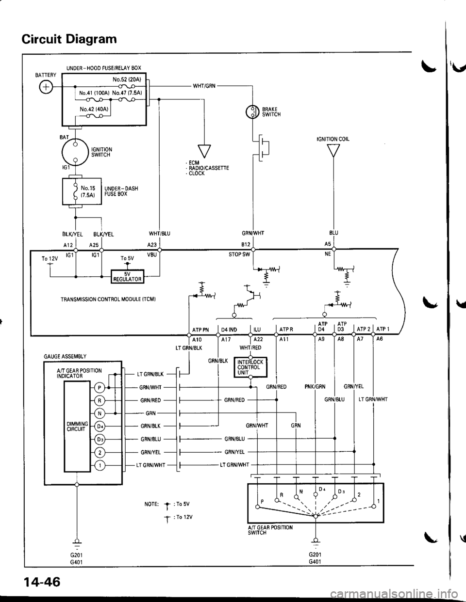
Circuit Diagram
UNDER.HOOD FUSE/BELAY BOX
No.41 (100A1 No.47 (7.5A)
\'
WHT/BLU
423
LTGRN/BLK
I
GRNI/VHT
GRN/RED
GRN
GBN/BI"K
GRN/8LU
GRN/YET
LT GRN,M/HT
NoTE: I :To5v
T :1o 12v
14-46
\,
GAUGE ASSEMBTY
AiT GEAR POSITIONINOICATOR
To lzv lGl
rRANsMrssroN coNTRoL M.DULE rrcMr -fu
*> =
g
=.
I f- J:*
rrppr lo+rlo lru lrrpn tflt ti]t lrrezlerer
5VFEGULATOR
F- GRN/BLU
l--- GRN/YEL
l-- t"T GRN,aWHT
'v
Page 653 of 1681
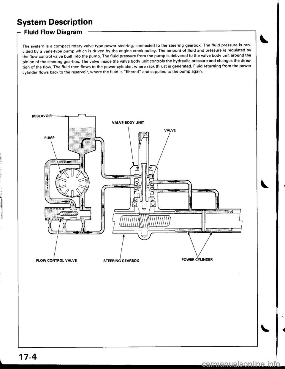
System Description
Fluid Flow Diagram
The system is a compact rotary-valve-type power steering, connected to the steering gearbox. The fluid pressure is pro-
vided by a vane-type pump which is driven by the engine crank pulley. The amount of fluid and pressure is regulated by
the flow control valve built into the pump. The fluid pressure from the pump is delivered to the valve body unit around the
pinion of the steering gearbox. The valve inside the valve body unit controls the hydraulic pressure and changes the direc-
tion of the tlow. The fluid then flows to the power cylinder, where rack thrust is generated. Fluid returning from the power
cylinder flows back to the reservoir, where the fluid is "filtered" and supplied to the pump again
li
I
VALVE BODY UNIT
GEARBOXFLOW CONTROL VALVEPOWER CYLINDER
17-4
Page 775 of 1681
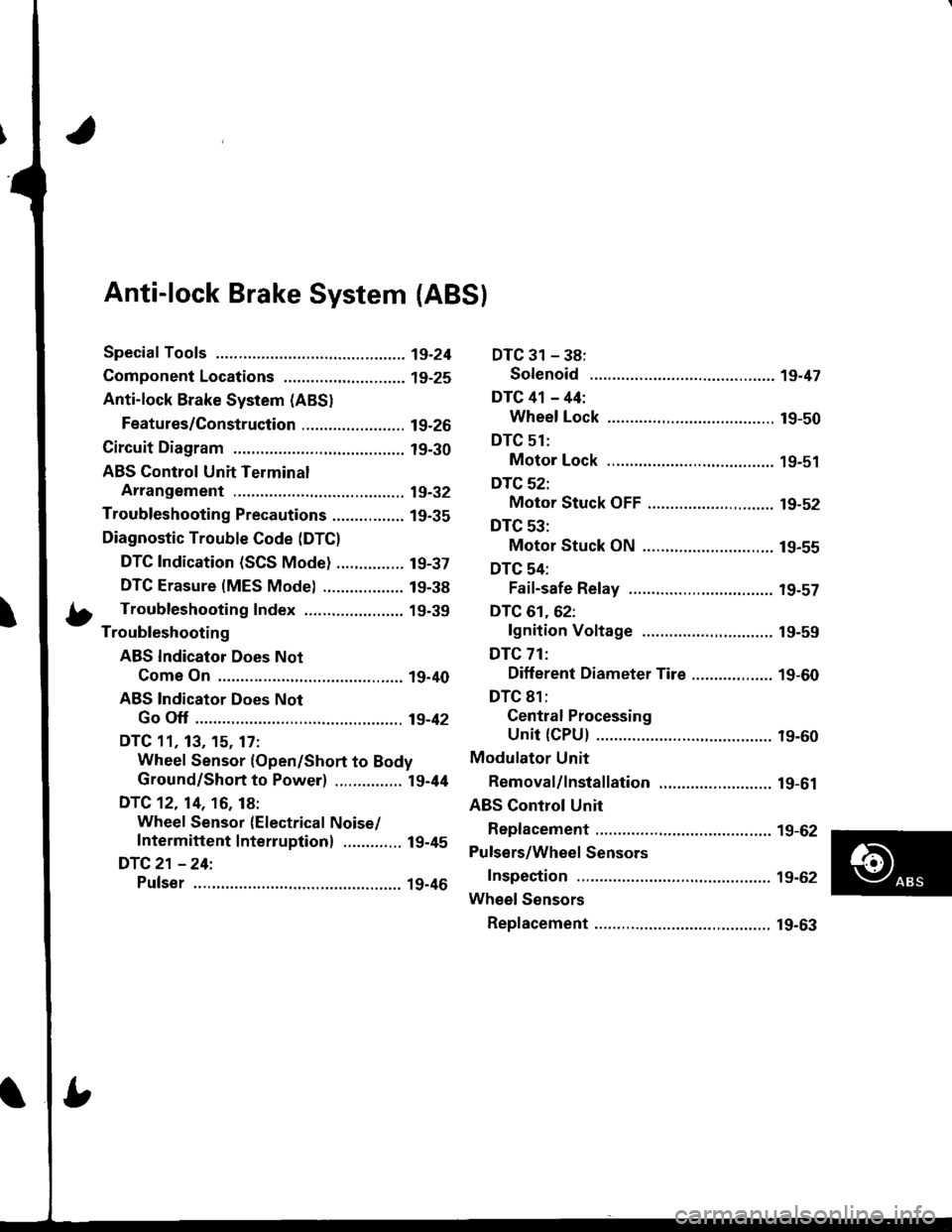
Anti-lock Brake System {ABS}
Speciaf Tools ............... 19-24
Component Locations,...........,..,........... 19-25
Anti-lock Brake System (ABSI
Features/Construction ....................... 19-2G
Circuit Diagram ........... 19-30
ABS Control Unit Terminal
Arrangement ........... 19-32
Troubleshooting Precautions ................ 1g-35
Diagnostic Trouble Code (DTC)
DTC Indication (SCS Mode) ............... t9-37
DTC Erasure {MES Mode) .................. 19-38
b Troubleshooting Index ...................... 19-39- Troubleshooting
ABS Indicator Does Not
Come On .............. 19-40
ABS Indicator Does Not
Go Off .............. ..... 19-42
DTC 11, 13, 15. 17:
Wheel Sensor (Open/Short to Body
Ground/Short to Power) ............... l9-44
DTC 12. 14, 16, 18:
Wheel Sensor (Electrical Noise/
Intermittent Interruption) ..........,.. 19-45
DTC21 -24:
Pulser ...,.......... ..... 19-46
DTC 31 - 38:
Solenoid .............. 19-47
DTC 41 - 44:
Wheel Lock .......... 19-50
DTC 51:
Motor Lock .......... 19-51
DTC 52:
Motor Stuck OFF ...................,........ 19-52
DTC 53:
Motor Stuck ON ............................. 19-55
DTC 54:
Fail-safe Relay ................................ t9-57
DTC 61.62:
lgnition Voltage ............................. 19-59
DTC 71:
Different Diameter Tire .................. 1 9-60
DTC 81:
Gentral Processing
Unit {CPU} ............ 19-60
Modulator Unit
Bemoval/lnstallation ......................... 19-61
ABS Control Unit
Replacement ............ 19-62
Pulsers/Wheel Sensors
Inspection ................ 19-62
Wheel Sensors
Replacement .,.......... 19-63
Page 782 of 1681
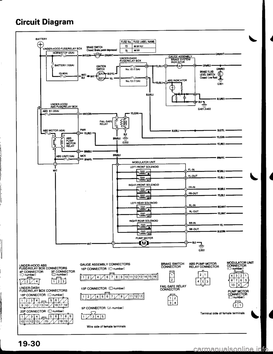
Gircuit Diagram
UIDES-HOOO FUSENELAY BOX
UNDER,HOOD ASSFUSSRELAY BOX CONN€CTORS4P CONNECTOR 3P CONNECTOR(O numb€r) (tr numb€r)
l./121./ 4l lrl2l3l
UNDER.DASHFUSFJRELAY BOX CONNECTORS18P CONNECTOR (O numb6r)
l235
I10121311a1,/67 t18
2op CONNECTOR (E number)
l356'78I
101l12/ 115t,/819
MAI(E S1IITCN06.d: 8.*! p.d.l @.!s.d
tGNtrotiSWITCH
p,-*@i
GAUGE ASSEMBLY CONNECTORS
16P CONNECTOR (O number)
SfMEL -
f,lBU -
Y&EtU -
*4
coiboz
EOWI-
BFAKE SWITCHCONNECTOR
fi
tr
FAIL,SAFE RELACONIiECTOR
Tr 121
M
A'ff.t#P;t"3.
ffi'
Jr:t r_E+?-|1]]
l.lXl. I tlL]jlJr:ly L-tr-J lLlAZ,)
PUMP MOTORCONNECTOF(tr numb€r)
,F.L?-]IJ
Tsrminal sids ol femalo tominals
5P CONNECTOR
f,rF-.Tt\
FUSE N0ftJSE UBEL IIAI,|E
15
t3P cONNEcToR (D numb€r)
19-30
Wke sido ol lomale l€rminels
Page 988 of 1681
iii
i
I
J
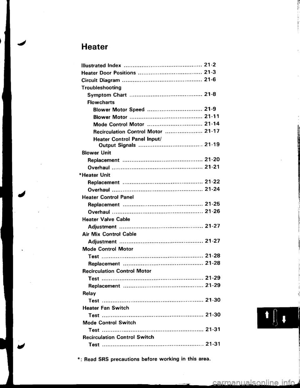
Heater
fffustrated Index ............. ......'..21-2
Heater Door Positions '....'........ 21-3
Circuit Diagram ....................... 21-6
Troubleshooting
Symptom Chart ............. '.....21-8
Flowcharts
Blower Motor Speed ...............'......'........ 21 -9
Blower Motor ............'......21-11
Mode Controf Motor ............ ............'... "' 21 -14
Recirculation Control Motor ......'...... "'.,.,. 21 -1 7
Heater Control Panel Input/
Output Signals ...'.......... 21-19
Blower Unit
Replacement ........ '....... ',..,.. 21-2O
Overhaul ",',..21-21
*Heater Unit
Repf acement .....'.....'........'.. 21'22
Overhaul .......21-24
Heater Control Panel
Repfacement ....... '..... '......... 21-25
Overhaul .......21-26
Heater Valve Cable
Adjustment '.. 21'27
Air Mix Control Cable
Adiustment ... 21-27
Mode Control Motor
Test .............. ..................... 21'24
Repfacement ....................... 21-24
Recirculation Control Motor
Test .............. ..................... 21-29
Repf acement .........'........ " ". 21-29
Relay
Test .............. ..................... 21-3O
Heater Fan Switch
Test .............. ....................' 21-30
Mode Control Switch
Test .............' "'..............'... 21-31
Recirculation Control Switch
Test .............. ..................... 21-31
*: Read SRS precautions before working in this area.
Page 993 of 1681
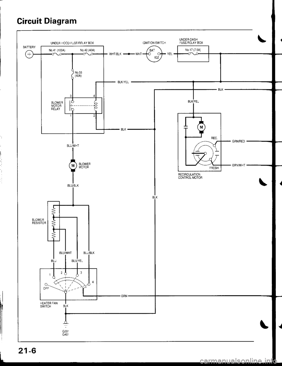
Circuit Diagram
R€CIRCULATIONcoNTROt MOTOR
UNDER HOOD FUSE/RELAY BOX
N0.41 (1004) N0.42 (40A)
,,\J.orr --'-- l,--
BtK
21-6
Page 1023 of 1681
![HONDA INTEGRA 1998 4.G Workshop Manual Circuit Diagram
CONDENSERFANRELAY
!
BTKFED FEO
II
VIecu1xzrccl IT(l
tql
i.tli*, Tf7 r-
IBIU/RED
I-1
8LU/REO
.*.. *(if ) PRESSUFE
Y SWTCH
YEL/N4]T
lvcDIODE
- BLUiRED
I ,,,,^,-.,
IY
r.--"-G8N
I,**,
Y HONDA INTEGRA 1998 4.G Workshop Manual Circuit Diagram
CONDENSERFANRELAY
!
BTKFED FEO
II
VIecu1xzrccl IT(l
tql
i.tli*, Tf7 r-
IBIU/RED
I-1
8LU/REO
.*.. *(if ) PRESSUFE
Y SWTCH
YEL/N4]T
lvcDIODE
- BLUiRED
I ,,,,^,-.,
IY
r.--"-G8N
I,**,
Y](/img/13/6069/w960_6069-1022.png)
Circuit Diagram
CONDENSERFANRELAY
!
BTKFED FEO
II
VIecu1xzrccl IT(l
tql
i.tli*, Tf7 r-
IBIU/RED
I-1
8LU/REO
.*.. *(if ) PRESSUFE
Y SWTCH
YEL/N4]T
lvcDIODE
- BLUiRED
I ,,,,^,-.,
IY
r.-'-"'-G8N
I,**',
Y ES:1i+31'
I
ts$'fts.,1
I
I
IBLK
I
G101
BLI(BED
I
I
I
,^r^r", IFANMoToRY
I
I
I
I8LK
T
G201G401
V
IBLU€LK
f7
IBLU/Y€L
V
IBLUMHT
V
IBLU
BLU/RED BLK,YEI
"fti.. i,, )
BLK
I
G151
Page 1132 of 1681
![HONDA INTEGRA 1998 4.G Workshop Manual Circuit Diagram (M/Tl
tJ
STARTEBCUT RELAY
)/
ll-G2o1G401
rAa rtFz5- r3
) -rr
CLUTCHINTERLOCKSW]TCH
IGNITIONX SWITCH
!_*",.^-*-G-l
"T"
BTKWHT BLKWHT
llr - tr |
BLKFED 8LU/BLK
- BLK,BE I__-lrror.oo*
I HONDA INTEGRA 1998 4.G Workshop Manual Circuit Diagram (M/Tl
tJ
STARTEBCUT RELAY
)/
ll-G2o1G401
rAa rtFz5- r3
) -rr
CLUTCHINTERLOCKSW]TCH
IGNITIONX SWITCH
!_*",.^-*-G-l
"T"
BTKWHT BLKWHT
llr - tr |
BLKFED 8LU/BLK
- BLK,BE I__-lrror.oo*
I](/img/13/6069/w960_6069-1131.png)
Circuit Diagram (M/Tl
tJ
STARTEBCUT RELAY
)/
ll-G2o1G401
rAa rtFz5- r3
) -rr
CLUTCHINTERLOCKSW]TCH
IGNITIONX SWITCH
!_*",.^-*-G-l
"T"
BTKWHT BLKWHT
llr - tr |
BLKFED 8LU/BLK
- BLK,BE' I__-lrror.oo*
I I
+Yffii'"'Tf'o' | |
u"T-l
i,t^il'r** | |
=-T--. I
twt t
l$*Tl r
IA II
BLK
tY--lt I-|ffim-
|
rl
UNDEB HOOD FUSE/BELAY BOX
No 41 (100A) N0.42 (404)