stop start HONDA INTEGRA 1998 4.G User Guide
[x] Cancel search | Manufacturer: HONDA, Model Year: 1998, Model line: INTEGRA, Model: HONDA INTEGRA 1998 4.GPages: 1681, PDF Size: 54.22 MB
Page 784 of 1681
![HONDA INTEGRA 1998 4.G User Guide ABS Gontrol Unit Terminal Arrangement
ABS CONTROL UN]T 22P CONNECTOR
Wire side oI female t6rminals
Terminal
numbel
Wire
Golor
Terminsl sign
{Terminal
namet
Description
Measurgmgnt
TerminalConditions
{ HONDA INTEGRA 1998 4.G User Guide ABS Gontrol Unit Terminal Arrangement
ABS CONTROL UN]T 22P CONNECTOR
Wire side oI female t6rminals
Terminal
numbel
Wire
Golor
Terminsl sign
{Terminal
namet
Description
Measurgmgnt
TerminalConditions
{](/img/13/6069/w960_6069-783.png)
ABS Gontrol Unit Terminal Arrangement
ABS CONTROL UN]T 22P CONNECTOR
Wire side oI female t6rminals
Terminal
numbel
Wire
Golor
Terminsl sign
{Terminal
namet
Description
Measurgmgnt
TerminalConditions
{lgnition swhch ON {ll}}Voltage
1BLK/WHTGND3(Ground 3)
Ground1.GNDBelow 0.3 V
4GRN/REDPARK
{Parking)
Detects parking brake
switch signal4-GNDParking
brake
PulledBelow 0.3 V
Battery voltage
LT GRN/
BLK
FLW (-)
{FronLleft
wheel negative)
Detects left-front wheel
sensor srgnal
0.053 V or
above
0sci\oscope:
0.15 Vp-p or
above
7GBN/ORN
FLW (+)
(Front-left
wheel positive)- | Turn wheel at
E
1 turntsecona
l'GRN
FRW (-)
(Front-right
wheel negative)
Detects right-f ront wheel
sensor slgnal
8-9
1 FR\N (+)
I \GRN/BLK (Front-right
I I wheelpositiveStops0.25 - 1.15 V
10GRN/WHTSTOPDetects brake switch signal1O.GNDBrake pedalDepressedBaftery voltage
ReleasedBelow 0.3 V
11BLK/TELtG2
(lgnition 2)
Power source for activating
the system11-GNDlgnition
switch
oN {I)Battery voltage
Start (lll)Below 0.3 V
19-32
Page 1319 of 1681

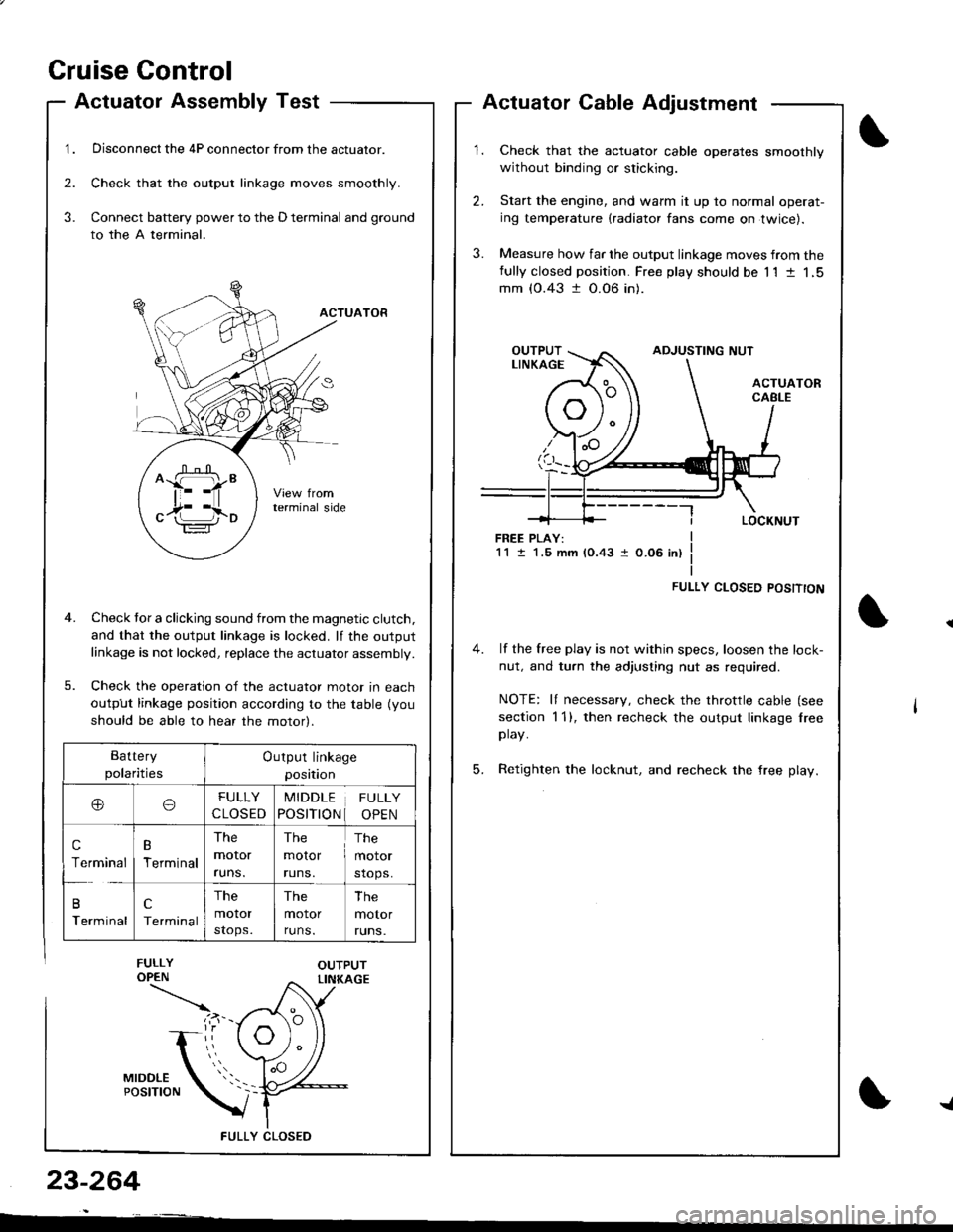
Cruise Gontrol
1.
Actuatol Assembly Test
Disconnect the 4P connector from the actuator.
Check that the output linkage moves smoothly.
Connect battery power to the D terminal and ground
to the A terminal.
ACTUATOR
Check tor a clicking sound from the magnetic clutch.
and that the output linkage is locked. lf the outputlinkage is not locked, replace the actuator assembly.
Check the operation of the actuator moror In eacn
output linkage position according to the table (you
should be able to hear the motor).
FULLY CLOS€D
2.
3.
3.
23-264
Actuator Cable Adjustment
Check that the actuator cable operates smoothly
without binding or sticking.
Start the engine, and warm it up to normal operat-
ing temperature (radiator fans come on twice).
Measure how far the output linkage moves from thefully closed position. Free play should be 11 t 1,5mm (0.43 t 0.06 in).
FREE PLAY:1M.5 mm (0.43 1 0.06 in)
FULLY CLOSED POSITTON
4. lf the free play is not within specs, loosen the lock-
nut, and turn the adjusting nut as required.
NOTE: It necessary, check the throttle cable (see
section 1 1), then recheck the output linkage lreeplay.
5. Retighten the locknut, and recheck the free play.
^ffi"
c17i l,io
Battery
polaritiesOutput linkage
position
ooFULLY
CLOSED
MIDDLE
POSITION
FULLY
OPEN
c
Terminal
B
Terminal
The
moror
runs.
The
molor
runs.
The
motor
stops.
B
Terminal
c
Terminal
The
motor
stops.
The
motor
runs.
The
motor
runs.
{
Page 1507 of 1681

Wiperffasher (contd)
- How the Circuit Works
When the ignition switch is in ON (ll) or START (lll),
battery voltage is applied to lhe windshield
wiper/washer switch, and the windshield wiper
motor.
Low Speed
When you turn the wiper switch to LO, the wiper
motor's low speed winding is grounded through the
BLU wire and the LO speed contacts of the wiper
switch at G401, and the wipers run at low speed.
ParUOfi
When you turn the wiper switch OFF, the integrated
control unit (PARK input) grounds the wiper motor
through the BLUMHT wire. The cam switch on the
motor signals the integrated control unit that the
wipers are in the PARK position; the control unit
then removes ground from the motor, and the
wipers stop in the PARK position.
High Speed
When the wiper switch is in Hl, the high speed
windings ol the windshield wiper motor are
grounded through the BLUI/EL wire and the Hl
contacts of the wiper switch at G401 , and the
wipers run at high speed.
Intermittent
When the wiper switch is in lNT, battery voltage is
applied through the YEUBLU wire to the integrated
control unit (lntermittent wiper ON input). The
integrated control unit (lntermittenvPark Wiper
Control) grounds the low speed windings of the
wiper motor and the wipers make a single sweep
every few seconds (See Low Speed above). When
the wiper returns to the PARK position, the park
switch applies battery voltage through the
BLUMHT wire to the integrated control unit (PARK
input), and the wipers stop in the PARK position.
91-2
Mist
When you pull the wiper switch down to MIST
position, the high speed windings of the wiper motor
are grounded through the BLU//EL wire and the
closed contacts of the mist switch at G401, and the
wipers make one pass across the windshield at high
speed. The PABKOFF tunction then takes over and
the wrpers stop in the PARK position.
Washer
When you pull the wiper switch toward you to turn on
the washer switch, battery voltage is applied to the
washer motor. The motor pumps fluid onto the
windshield until you release the lever. On models
with combined wiper/washer operation (Canada), the
integrated control unit (windshield washer ON input)
senses power al the BLI(GRN wire terminal and
runs the washer motor whenever the wioers run.
Reter to the Service irlanual (Section 23, Electrical)
for specific tests or troubleshooting procedures.