stop start HONDA INTEGRA 1998 4.G Workshop Manual
[x] Cancel search | Manufacturer: HONDA, Model Year: 1998, Model line: INTEGRA, Model: HONDA INTEGRA 1998 4.GPages: 1681, PDF Size: 54.22 MB
Page 252 of 1681
How to Read Flowcharts
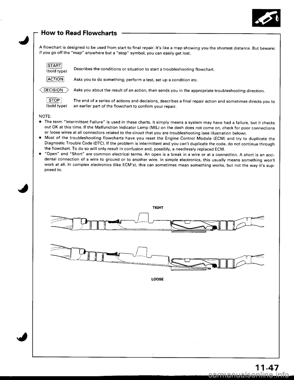
A flowchart is designed to be used from start to final repair. lt's like a map showing you the shone$ distance. But beware:if you go off the "map" anywhere but a "stop" symbol, you can easily get lost.
FTARN(bold type)
FcroNl
@>
sroFl
(bold type)
NOTE:
. The term "lntermittent Failure" is used in these chans. lt simply means a system may have had a failure, but it checksout OK at this time. lf the Malfunction lndicator Lamp (MlL) on the dash does not come on, check for poor connectionsor loose wires at all connectors related to the circuit that you are troubleshooting (see illustration below).. Most of the troubleshooting flowcharts have you reset the Engine Control Module (ECM) and try to duplicate theDiagnostic Trouble Code (DTC). lf the problem is intermittent and you can't duplicate the code, do not continue throughthe flowchart. To do so will only result in confusion and, possibly, a needlessly replaced ECM.. "Open" and "Short" are common electrical terms. An open is a break in a wire or at a connection. A short is an acci-dental connection of a wire to ground or to another wire. In simple electronics, this usually means something won,twork at all. In complex electronics (like ECM's), this can sometimes mean something works, but not the way rr s sup-posed 10.
Describes the conditions or situation to start a troubleshootinq flowchart
Asks you to do something; perform a test, set up a condition etc.
Asks you about the result of an action, then sends you in the appropriate troubleshooting direction.
The end of a series of actions and decisions, describes a final repair action and sometimes direcls you toan earlier part of the flowchart to confirm your repair.
11-47
Page 316 of 1681
ldle Speed Setting
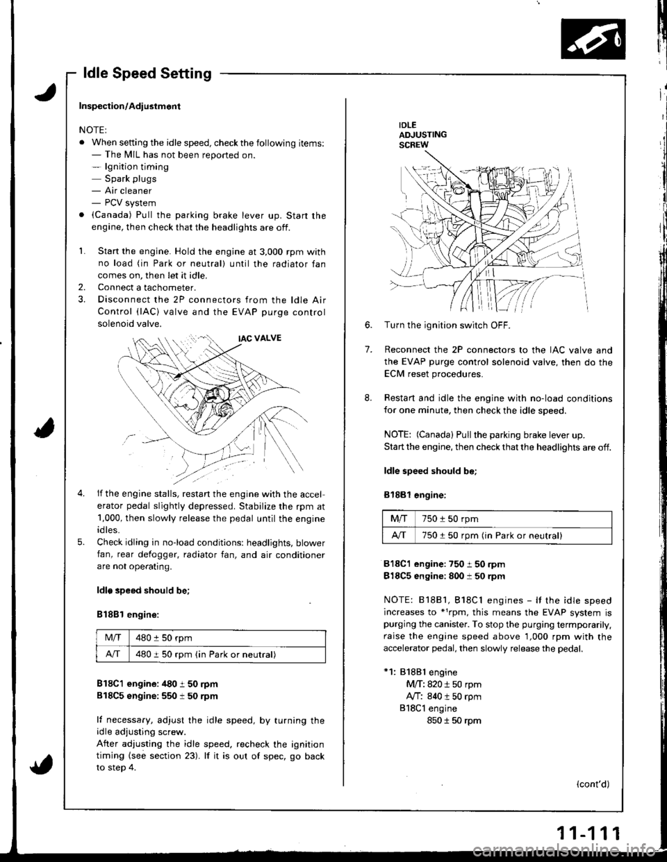
IDLEADJUSTINGSCREW
7.
6.Turn the ignition switch OFF.
Reconnect the 2P connectors to the IAC valve and
the EVAP purge control solenoid valve, then do the
ECM reset procedures.
Restart and idle the engine with no-load conditions
for one minute, then check the idle speed.
NOTE: (Canada) Pullthe parking brake lever up.
Start the engine, then check that the headlights are off.
ldle speed should be;
Bl88l €ngine:
Mfi750 i 50 rpm
A/T750150 rpm (in Park or neutral)
818C1 engine:750 i 50 rpm
818C5 engine: 800 i 50 rpm
NOTE: 81881, Bl8Cl engines - It the idle speed
increases to *1rpm, this means the EVAP system ispurging the canister. To stop the purging termporarily.
raise the engine speed above 1,000 rpm with the
accelerator pedal, then slowly release the pedal.
*1: 81881 engine
M/T: 820 i 50 rpm
Ay'T: 840 t 50 rpm
818Cl engine
850 I 50 rpm
(cont'd)
Inspection/Adiustmont
NOTE:
. When setting the idle speed, checkthe following items:- The MIL has not been reported on.- lgnition timing
Spark plugs- Air cleaner- PCV system
. (Canada) Pull the parking brake lever up. Start the
engine, then check that the headlights are off.
1. Start the engine. Hold the engine at 3,000 rpm with
no load (in Park or neutral) until the radiator fan
comes on, then let it idle,
Connect a tachometer.
Disconnect the 2P connectors from the ldle Air
Control (lAC) valve and the EVAP purge control
solenoid valve.
2.
5.
if the engine stalls, restan the engine with the accel
erator pedal slightly depressed. Stabilize the rpm at
1,000, then slowly release the pedal until the engine
idles.
Check idling in no-load conditions: headlights, blower
fan, rear defogger, radiator fan, and air conditioner
are not ope€tlng.
ldlo speed should be;
B188l engine:
Mlf480 :l 50 rpm
A/T480 i 50 rpm (in Park or neutral)
B18C1 engine: /t80 t 50 rpm
818C5 sngine:550 t 50 rpm
lf necessary, adjust the idle speed, by turning theidle adjusting screw.
After adjusting the idle speed, recheck the ignition
timing {see section 23). lf it is out of spec, go back
to steo 4.
Page 337 of 1681
In
Intake Air System
Throttle Body
$;
Description
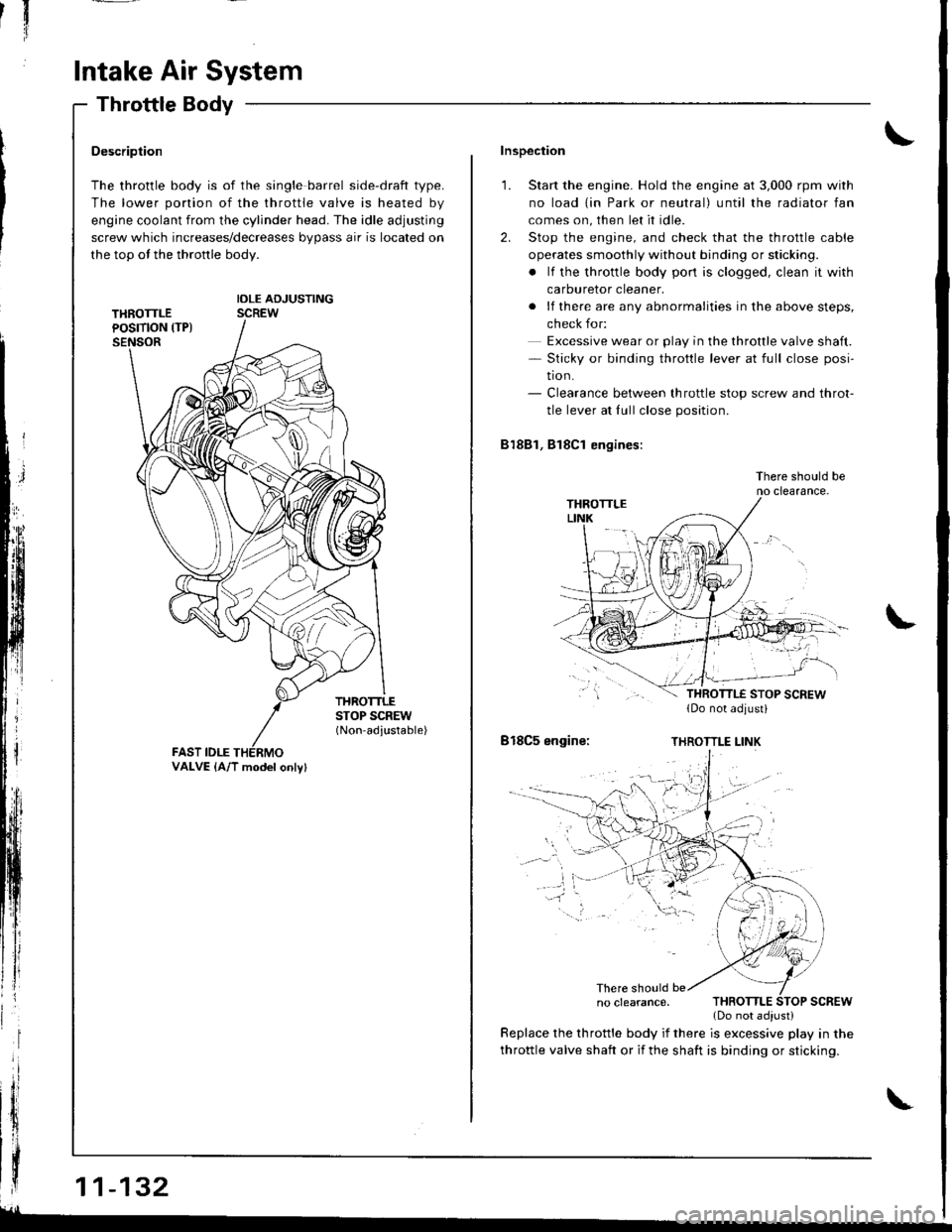
The throttle body is of the single barrel side-draft type.
The lower portion of the throttle valve is heated by
engine coolant from the cylinder head. The idle adjusting
screw which increases/decreases bypass air is located on
the top ot the thronle body.
IDLE ADJUSTINGSCREW
THROTTLESTOP SCREW(Non-adjustable)
FAST IDLE
| | .o clearance. THRoTTLE SToP scREw
{ | | _ .lDonotadiust)
| | y:::::::T,"9":::.'"Tl::f ,::i1::"1" fllyll-'n"
VALVE {A/T model onlv}
Inspection
1. Start the engine. Hold the engine at 3,000 rpm with
no load {in Park or neutral) until the radiator fan
comes on, then let it idle.
2. Stop the engine, and check that the throttle cable
operates smoothly without binding or sticking.
. lf the throttle body pon is clogged, clean it with
carburetor cleaner.
. lf there are any abnormalities in the above steps,
check for:
Excessive wear or play in the throttle valve shaft.- Sticky or binding throttle lever at full close posi-
tion.- Clearance between throttle stop screw and throt-
tle lever at fullclose position.
81881, Bl8Cl engines:
There should beno clearance.
818C5 engine:THROTTLE LINK
There should be
throttle valve shaft or if the shaft is binding or sticking.
glL-
Page 421 of 1681
Description
{cont'd)
Gsar Selection
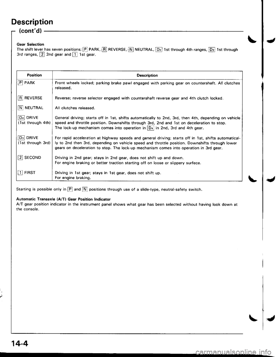
The shift lever has seven positions; @ PARK, E REVERSE, N NEUTRAL. [Dt l st through 4th ranges, @ 1st through
3rd ranges, @ 2nd gear and [ 1sr gear.
Starting is possible only in @ and N positions through use of a slide-type, neutral-safety switch.
Automatic Transaxle (A/T) Gear Position Indicator
A/T gear position indicator in the instrument panel shows what gear has been selected without having look down at
the console.
PositionDescription
E PARK
E REVERSE
N NEUTRAL
[p"l DRrvE
('lst through 4th)
I p3l DRrvE
(1st through 3rd)
E sEcoND
E FIRST
F.ont wheels locked; parking brake pawl engaged with parking gear on countershaft. All clutches
released.
Reverse; reverse selector engaged with countershatt reverse gear and 4th clutch locked.
All clulches released.
General driving; sta.ts o{f in 1st, shitts automatically to 2nd, 3rd, then 4th, depending on vehicle
speed and throttle positlon. Downshifts through 3rd, 2nd and 1st on deceleration to stop.
The lock-up mechanism comes into operation in @ in Zna, 3rd and 4th gear.
For rapid acceleration at highway speeds and general driving; starts otf in 1st, shifts automatical-
ly to 2nd then 3rd, depending on vehicle speed and throttle position. Downshifts through lowe.gears on deceleration to stop. The lock-up mechanism comes into operation in 3rd gear.
Driving in 2nd geat; stays in 2nd gear. does not shift up and down.
For engine braking or better traction starting otl on loose or slippery surlece.
Driving in 1st gear; stays in 1st gear, does not shift up.
For engine braking.
14-4
{
Page 502 of 1681
u
fj
\*J
14-85
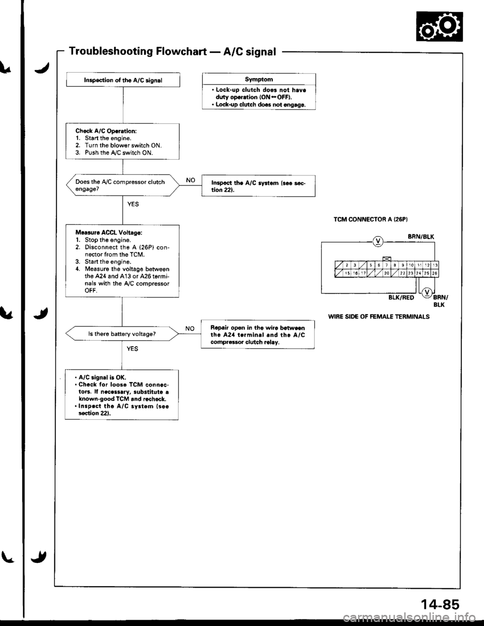
Inspsction of tho A/C aign.l
Ch.ck A/C Op.ration:1. Start the engine.2. Turn the blowerswitch ON.3. Push the r'y'C switch ON.
Moaluro ACCL Voltdg.:1. Stop the engine.2. Disconnect the A {26P) con-nector from the TCM.3. Start the engine.4. Measuro the voltage betwoontho A24 and A13 or 426 termi-nals with the Ay'C compressorOFF.
Ropair open in tho wira batwaenth. A24 termin.l and rhc A/Ccomprclsor clulch ralay.
ls therc battery voltage?
. A/C aignal is OK.. Chgck for loo3e TCM connoc-1013. lf neces3ary, 3ub3tituto dknown-good TCM rnd rcchock..Inspect tho A/C sy.tem lso.lection 221.
JSymp(om
' Lock-uD clutch dog3 not haveduty opor.tion ION *OFF).. Lock-up clutch doe3 not ongago.
TCM CONNECIOR A (26PI
J
BLK
WIRE SIDE OF FEMALE TERMINALS
Page 516 of 1681
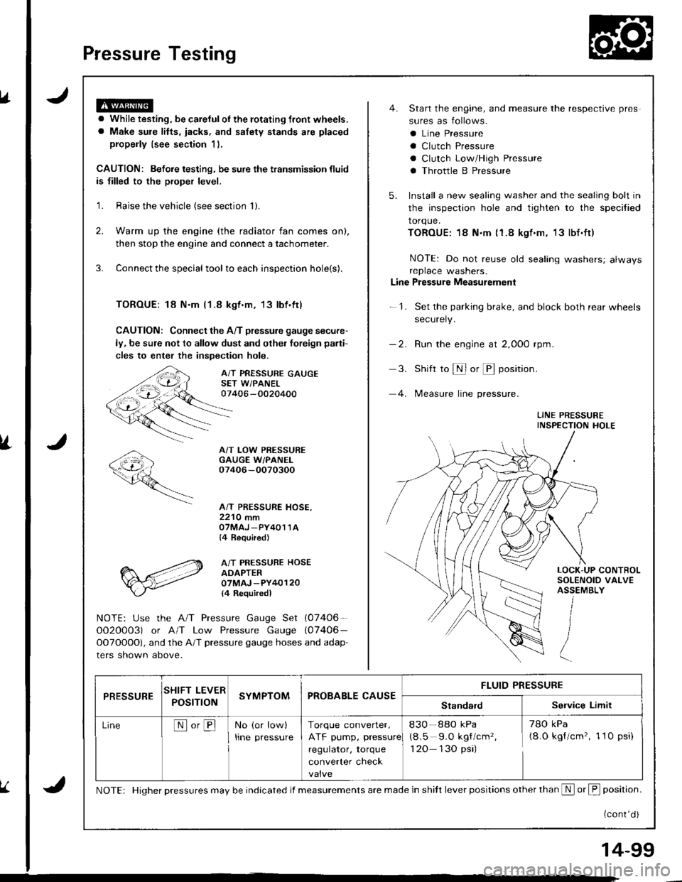
Pressure Testing
a While testing, be careJulot the rotating front wheels.
a Make sule litts, iacks, and safety stands are placed
properly (see section 1).
CAUTION: Befoie testing, be sure the transmission fluid
is filled to the proper level.
'1. Raise the vehicle {see section 'll.
2. Warm up the engine (the radiator fan comes on),
then stop the engine and connect a tachometer.
3. Connect the special tool to each inspection hole(s).
TOROUE: 18 N.m l1-8 kgt.m, 13lbf.ftl
CAUTION: Connect the A/T pressure gauge secure-
ly, be sure not to allow dust and olher foreign pani-
cles to enter the inspection hole.
A/T PRESSURE GAUGESET W/PANEL07406 -0020400
A/T LOW PRESSUREGAUGE W/PANEI.07406-OO70300
A/T PRESSURE HOSE,2210 mmOTMAJ _PY4O1 1A{4 Required}
A/T PRESSURE HOSEADAPTER07MAJ -PY40120
l4 Requiredl
NOTE: Use the A/T Pressure Gauge Set (07406-
OO2O0O3) or A/T Low Pressure Gauge (07406-
OOTOOOO), and the A/T pressure gauge hoses and adap-
ters shown above.
4. Start the engine, and measure the respective pres
sures as follows.
a Line Pressure
a Clutch Pressure
a Clutch Low/High Pressure
a Throttle B Pressure
5. Install a new sealing washer and the sealing bolt in
the inspection hole and tighten to the specified
torque.
TOROUE:18 N.m (1.8 kgf.m, 13lbf.ft)
NOTE: Do not reuse old sealing washers; alwaysreplace washers.
Line Pressure Measurement
-1. Set the parking brake, and block both rear wheels
securely.
-2. Run the engine at 2,000 rpm
3. Shift to S or @ position.
4. lMeasure line pressure.
LINE PRESSUREINSPECTION HOLE
LOCK-UP CONTROLSOLENOID VALVEASSEMBLY
PRESSURESHIFT LEVER
POST ONSYMPTOMPROBABLE CAUSEFLUID PRESSURE
StandardService Limit
LineNo,BNo (or low)
Irne pressure
Torque converter,
ATF pump, pressure
regulator, torque
converter check
830 88o kPa
(8.5 9.O kgf/cm'�,
1 20 130 psi)
78O kPa(8.O kgf/cm'�, 1 10 psi)
NOTE: Higher pressures may be indicated if measurements are made in shitt lever positions other than S or f, position.
{cont'd )
14-99
Page 670 of 1681
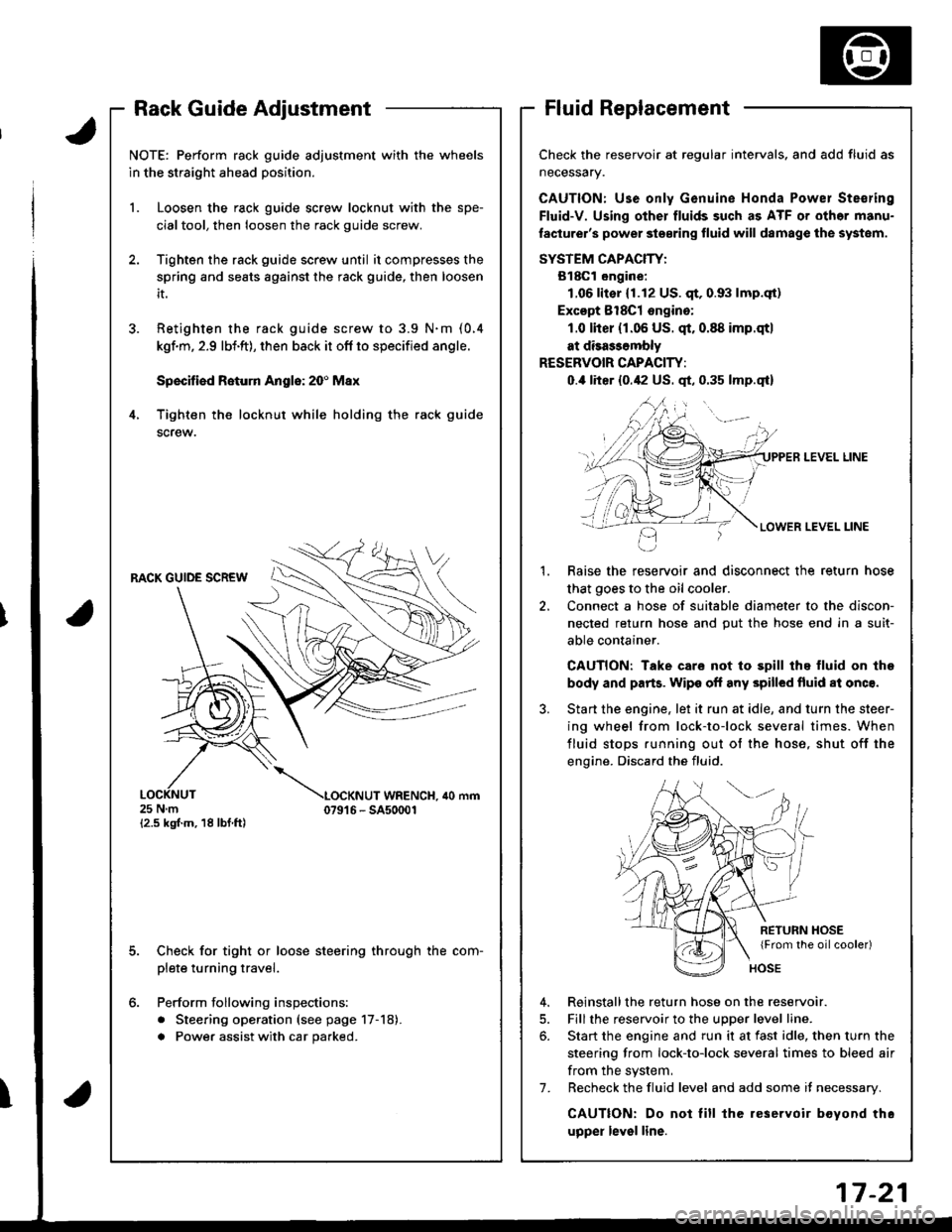
Rack Guide AdjustmentFluid Replacement
Check the reservoir at regular intervals, and add fluid as
neceSsary.
CAUTION: Use only Genuine Honda Powel Ste€ring
Fluid-V. Using other fluids such as ATF or othor manu-
laclurer's power ste€ring fluid will damag€ the systom.
SYSTEM CAPACIW:
B18Gl ongine:
1.06lit€r (1.12 US. qt,0.93 lmp.qt)
Excopt 8l8Cl ongino:
1.0 lher (r.06 US. qt.0.88 imp.qtl
at disa$ombly
RESERVOIR CAPACITY:
0.,0 liter {0.42 US. qt, 0.35 lmp.qt}
LEVEL LINE
LEVEL LINE
Raise the reservoir and disconnect the return hose
that goes to the oil cooler.
Connect a hose of suitable diameter to the discon-
nected return hose and put the hose end in a suit-
able container.
CAUTION: Take care not to spill thq fluid on lhe
body and parts. Wipe off any spilled fluid al onc€.
Start the engine. let it run at idle, and turn the steer-
ing wheel from lock-to-lock several times. When
fluid stops running out of the hose, shut off the
engine. Discard the fluid.
2.
RETURN HOSE{From the oilcooler)
4. Reinstallthe return hose on the reservoir.
5. Fill the reservoir to the uDDer level line.
6. Start the engine and run it at fast idle, then turn the
steering from lock-to-lock several times to bleed air
from the system,
7. Recheck the fluid level and add some it necessary.
CAUTION: Do not lill the reservoir boyond thc
upper level line.
J.
4.
NOTE: Perform rack guide adjustment with the wheels
in the straight ahead position.
1. Loosen the rack guide screw locknut with the spe-
cialtool, then loosen the rack guide screw.
Tighten the rack guide screw until it compresses the
spring and seats against the rack guide, then loosen
it.
Retighten ihe rack guide screw to 3.9 N.m (0.4
kgf.m, 2.9 lbi.ft), then back it ofl to specified angle.
Speciliad Roturn Anglo: 20' Max
Tighten th€ locknut while holding the rack guide
screw.
RACK GUIDE SCREW
25Nm{2.5 kgf.m, 18 lbf ft)
LOCKNUT WRENCH. ilo mm079't 6 - SA50001
E
6.
Check for tight or loose steering through the com-
plete turning travel.
Perform following inspections:
. Steering operation (see page 17-18).
a Power assist with car parked.
I
Page 767 of 1681
1.
8.
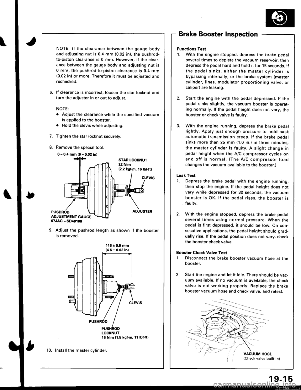
NOTE: lf the clearance between the gauge body
and adjusting nut is 0.4 mm (0.02 in), the pushrod-
to-piston clearance is 0 mm. However, if the clear-
ance between the gauge body and adjusting nut is
0 mm, the pushrod-to-piston clearance is 0.4 mm(0.02 in) or more. Therefore it must be adjusted and
rechecked.
lf clearance is incorrect, loosen the star locknut and
turn the adjuster in or out to adjust.
NOTE:
. Adjust the clearance while the specified vacuum
is applied to the booster.
. Hold the clevis while adjusting.
Tighten the star Iocknut securely.
Remove the special tool.
0 - o.il mm l0 - 0.02 inl
Brake Booster Inspection
Functions Tgst
1. With the engine stopped, depress the brake pedal
several times to deplete the vacuum reservoir, then
depress the pedal hard and hold it for 15 seconds. ll
the pedal sinks, either the master cylinder is
bypassing internally; or the brake system (master
cylinder, lines, modulator proportioning valve, orcaliper) are leaking.
Start the engine with the pedal depressed. lf thepedal sinks slightly, the vacuum booster is operat-
ing normally. lf the pedal height does not vary, the
booster or check valve is faulty.
With the engine running, depress the brake pedal
lightly. Apply just enough pressure to hold back
automatic transmission creep, lf the brake pedal
sinks more than 25 mm (1.0 in.) in three minutes,
the master cylinder is faulty. A slight change inpedal height when the A,,/C compressor cycles on
and off is normal. (The A/C compressor load
changes the vacuum available to the booster.)
Leak Test
1. Depress the brake pedal with the engine running,
then stop the engine. lf the pedal height does not
vary while depressed for 30 seconds, the vacuum
booster is OK. lf the pedal rises, the booster is
fau lty.
2. With the engine stopped, depress the brake pedal
several times using normal pressure. When thepedal is first depressed, it should be low. On con-
secutive applications, the pedal height should grad-
ually rise. lf the pedal position does not vary, check
the booster check valve.
Boostor Ch€ck Valve T6st
1. Disconnect the brake booster vacuum hose at the
booster,
Start the engine and let it idle. There should be vac-
uum available. It no vacuum is available. the check
valve is not working properly. Replace the brake
booster vacuum hose and check valve, and retest.
VACUUM HOSE(Check valve built-in)
STAR LOCKNUT22 t{.m12.2 ksl.m, 16lbf.ftl
cLEVtS
ADJUSTER
ADJUSTMENT GAUGE07JAG - SD40t00
9. Adjust the pushrod length as shown if the booster
is removed.
1161 0.5 mm14.61 0.02 inl
PUSHRODLOCKNUT15 N m 11.5 kgf m, 11 lbf'ftl
10. Instali the master cylinder.
Page 778 of 1681
.,i
,I
Anti-lock Brake SYstem (ABS)
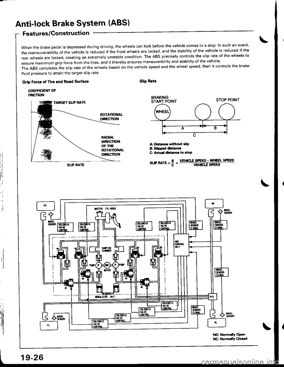
when the brake pedal is depressed during driving, the wheels can lock before the vehicle comes to a stop. In such an event.
the maneuverability of the vehicle is reduced if the front wheels are locked, and the stability of the vehicle is reduced if the
rear wheels are locked, creating an extremely unstable condition. The ABS precisely controls the slip rate o{ the wheels to
ensUre maximum grip force from the tires, and it thereby ensures maneuverbiIity and stabiIity of the vehicIe.
The ABS calculates the slip rate of the wheels based on the vehicle speed and the wheel speed. then it controls the brake
fluid oressure to attain the target slip rate
Features/Gonstructio n
Grip Foact ot Ti.c tnd Rotd Surfuco
COEFFICIEUT OFFNIG"TPN
Slip Rrtr
BRAKINGSTART POINT
i'l
A: f'3t rp withoul .lip
B: SIDp.d dirt.nc.G Actu.ldtt nc.io.top
sr.n arrr = f =
STOP POINTTARGET SUP RATE
SUP FATEVEHICT.C S'EEO - wlCEL SPEED
NO: Notm.lly oP.n
l{C: Noirnrly qo..d
19-26
Page 780 of 1681
Anti-lock Brake System (ABS)
Features/Construction (cont'd)
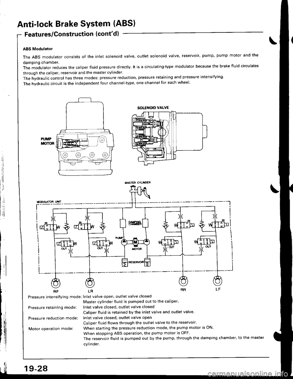
ABS Modulatol
The ABS modulator consists of the inlet solenoid valve, outlet solenoid valve, reservoir, pump, pump motor and the
damping chamber.
The modulator reduces the caliper fluid pressure directly. lt is a circulating-type modulator because the brake fiuid circulates
through the caliper, reservoir and the master cylinder.
The hydraulic control has three modes: pressure reduction, pressure retaining and pressure intensiiying
The hvdraulic circuit is the independent four channel-type, one channel tor each wheel'
L-__
RF LR
Pressure intensifying mode: Inlet valve open, outlet valve closed
Master cvlinder fluid is pumped out to the caliper.
Inlet valve closed, outlet valve closed
Caliper fluid is retained by the inlet valve and outlet valve.
lnlet valve closed, outlet valve open
Caliper fluid flows through the outlet valve to the reservolr'
When starting the pressure reduction mode, the pump motor is ON.
When stopping ABS operation, the pump motor is OFF.
The reservoir fluid is pumped out by the pump, through the damping chamber, to the master
cylinder.
\
Pressure retaining mode:
Pressure reduction mode:
Motor operation mode:
sott orD vALvE
@@-@@
TASIEF CYLI'OEF
19-24