timing belt HONDA INTEGRA 1998 4.G User Guide
[x] Cancel search | Manufacturer: HONDA, Model Year: 1998, Model line: INTEGRA, Model: HONDA INTEGRA 1998 4.GPages: 1681, PDF Size: 54.22 MB
Page 184 of 1681
3.
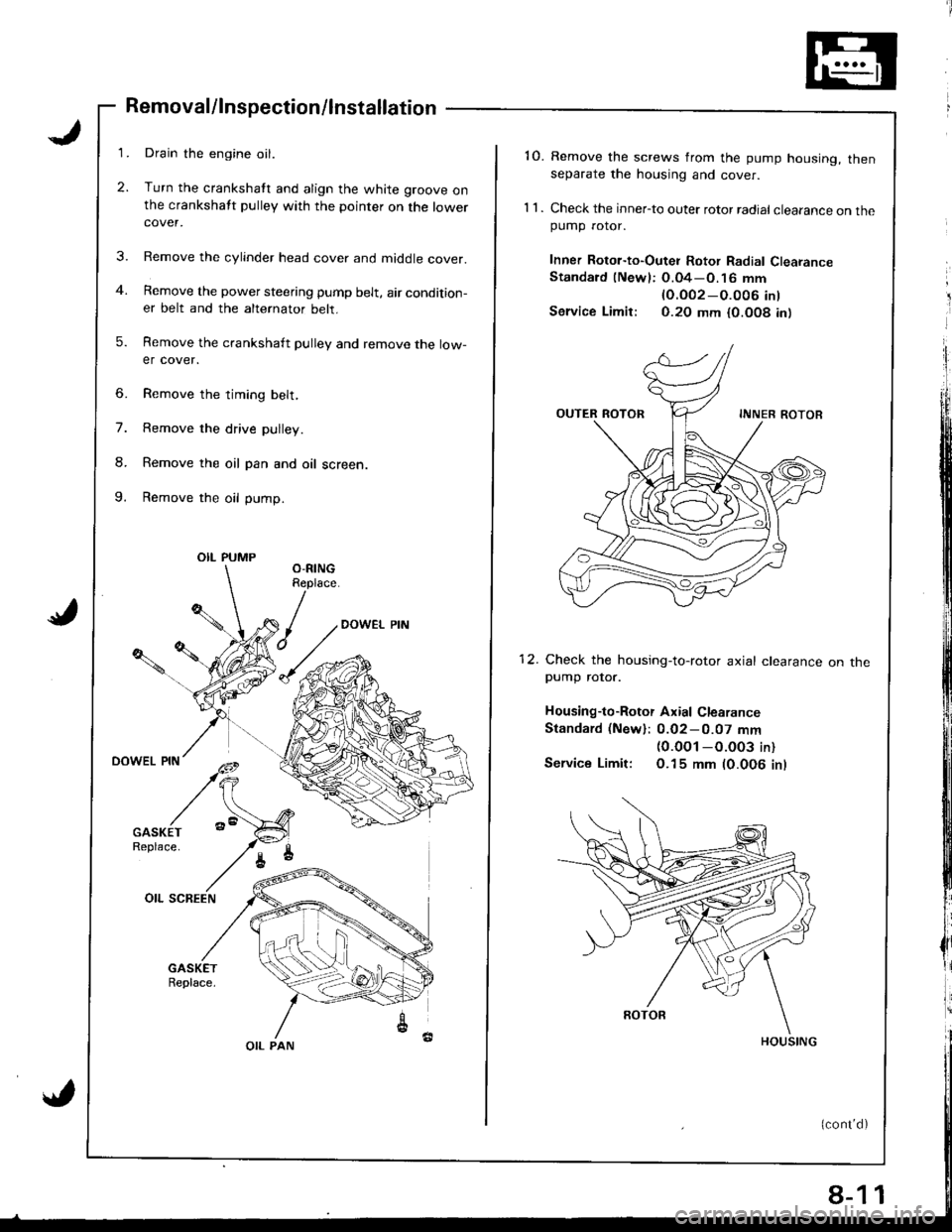
Removal/lnspection/lnstallation
Drain the engine oil.
Turn the crankshatt and align the white groove onthe crankshatt pulley with the pointer on the lowercover.
Remove the cylinder head cover and middle cover.
Remove the power steering pump belt, air condition-er belt and the alternator belt.
Remove the crankshaft pulley and remove the low-er cover.
6. Remove the timing belt,
7. Remove the drive pulley.
8. Remove the oil pan and oil screen.
9. Remove the oil pump.
OIL PUMP
OIL PAN
8-1
'10. Remove the screws from the pump housing, thenseparate the housing and cover.
1 1 . Check the inner-to outer rotor radial clearance on thepumD rotor.
Inner Rotor-to-Outei Rotor Radial ClearanceStandard (Newl: O.04-O.16 mm
lO.OO2-O.O06 int
Service Limir: 0.20 mm {0.O08 in)
12. Check the housing-to-rotor axial clearancepump rotor.
Housing-to-Rotor Axial Clearance
Standard (New): 0.02-0.07 mm(0.0O1 -O.003 in)
Service Limit: O.15 mm (0.006 inl
on tne
1
Page 205 of 1681
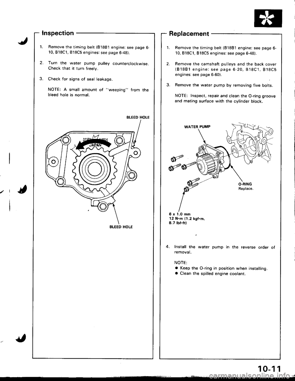
Inspection
Remove the timing belt (81881 engine: see page 6-10, B'l8Cl,818C5 engines: see page 6-48).
Tu.n the water pump pulley counterclockwise.Check that it turn freely.
Check for sign6 of seal leakage.
NOTE: A small amount of "weeping" trom thebleed hole is normal.
BLEED HOLE
Remove the timing belt (81881 engine: see page 6-
10,818C1, Bl8C5 engines: see page 6-48).
Remove the camshaft pulleys and the back cover(B'1881 engine: see page 6-20, 818C1, 818C5
engines: see page 6-60).
Remove the water pump by removing flve bolts.
NOTE: Inspect, repair and clean the O-ring groove
and mating surface with the cylinder block,
Replacement
6 x 1.0 mm12 N.m 11.2 kgt.m,8.7 tbf.tt)
4. Install the water pump in the reverse order ofremoval.
a Keep the O-ring in position when installing.a Clean the spilled engine coolant.
BLEED HOL€
10-1 1
Page 241 of 1681
Troubleshooting
Troubleshooting Procedures (cont'd)
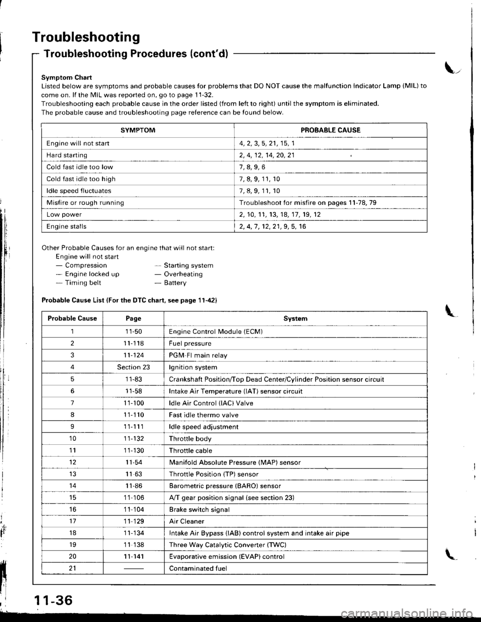
Symptom Chart
Listed below are symptoms and probable causes for problems that DO NOT cause the malfunction Indicator Lamp (MlL) to
come on. lf the MIL was reported on, go to page 11-32.
Troubleshooting each probable cause in the order listed (from left to right) until the symptom is eliminated.
The probable cause and troubleshooting page relerence can be found below.
Other Probable Causes for an engine that will not start:
Engine will not sta rt- Compression- Engine locked up- Timing belt
\_
- Starting system- Overheating- Battery
'4,
It
Probable Cause List (For the DTC chart. see page 11-421
Probable CausePageSystem
111-50Engine Control Module (ECM)
211118Fuel pressure
311-124PGM-Fl main relay
4Section 23lgnition system
51 1-83Crankshaft Position/ToD Dead Center/Cylinder Position sensor circuit
11-58Intake Air Temperature (lAT) sensor circuit
71 '�t- 100ldle Air Control (lAC) Valve
811110Fast idle thermo valve
I11lllldle speed adjustment
'1011-132Throttle body
111 1-130Throttle cable
1211-54lvlanifold Absolute Pressure {MAP) sensor
IJ1163Throttle Position {TP) sensor
1411-86Barometric pressure (BARO) sensor
1 '1 106A/T gear position signal {see section 23)
16'1 1 104Brake switch signal
1711 129Air Cleaner
181 1- 134Intake Air Bypass {lAB} control system and intake air pipe
19'1 1 138Three Way Catalytic Convener (TWC)
2011-141Evaporative emission (EVAP) control
21Contaminated fuelll ll 21 | - | cont"-in"t"o tu"
11 l-
I
,l 11-36
-
SYMPTOMPROBABLE CAUSE
Engine will not stan4, 2, 3,5, 21, 15, 1
Hard starting2, 4, 12, 14,20,21
Cold fast idle too low
Cold fast idle too high7, 8, 9, 11, r0
ldle speed fluctuates7,8,9,11,10
Misfire or rough runningTroubleshoot for misfire on pages 11-78,79
Low power2, 10,'t1, 13, 14, 17, 19, 12
Engine stalls2, 4,1 , 12,21,9, 5, 16
Page 248 of 1681
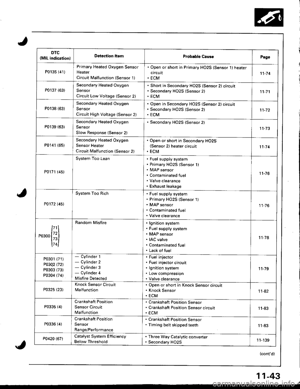
DTC(MlL indicationlDeteciion ltemProbable CausoPage
P013s {41)
Primary Heated Oxygen Sensor
Heater
Circuit Malfunction {Sensor '1)
. Open or shon in Primary HO2S (Sensor 1) heater
circuit. ECM1't-74
P0137 (63)Secondary Heated Oxygen
Sensor
Circuit Low Voltage (Sensor 2)
Short in Secondary HO2S (Sensor 2) circuit
Secondary H02S {Sensor 2)
ECM11-7'l
P0138 {63)
Secondary Heated Oxygen
Sensor
Circuit High Voltage (Sensor 2)
Open in Secondary HO2S (Sensor 2) circuit
Secondary HO2S (Sensor 2)
ECM
P0139 (63)Secondary Heated Oxygen
Sensor
Slow Response (Sensor 2)
Secondary HO2S (Sensor 2)
P0141 (651Secondary Heated Oxygen
Sensor Heater
Circuit Malfunction (Sensor 2)
. Open or short in Secondary HO2S(Sensor 2) heater circuit. ECM11-'14
P0171 (45)
System Too LeanFuel supply system
Primary HO2S {Sensor I )MAP sensor
Contaminated fuel
Valve clearance
Exhaust leakage
11-76
P0172 t45l
System Too RichFuel supply system
Primary HO2S (Sensor 1)
MAP sensor
Contaminated fuel
Valve clearance
11.76
,...,{iil
174l
Random Misfirelgnition system
Fuel supply system
MAP sensor
IAC valve
Contaminated fuel
Lack offuel
't 1-78
P0301 (71)
P03Q2 l'121
P0303 (73)
P0304 (74)
- Cylinder 1- Cylinder 2- Cylinder 3- Cylinder 4
Misfire Detected
Fuel injector
Fuel injector circuit
lgnition system
Low compression
Valve clearance
11-79
P0325 {23)
Knock Sensor Circuit
MalfunctionOpen or short in Knock Sensor circuit
Knock Sensor
ECM11-82
P0335 (4)Crankshaft Position
Sensor Circuit
Malfunction
Crankshaft Position Sensor
Crankshaft Position Sensor circuit
ECM1 1-83
P0336 (4)Crankshaft Position
Sensor
Range/Performance
. Crankshaft Position Sensor. Timing belt skipped teethIl-83
P0420 (67)Catalyst System Efficiency
Below Threshold
. Three Way Catalytic converter. Secondary HO2S11-139
(cont'd)
11-43
Page 1058 of 1681
J
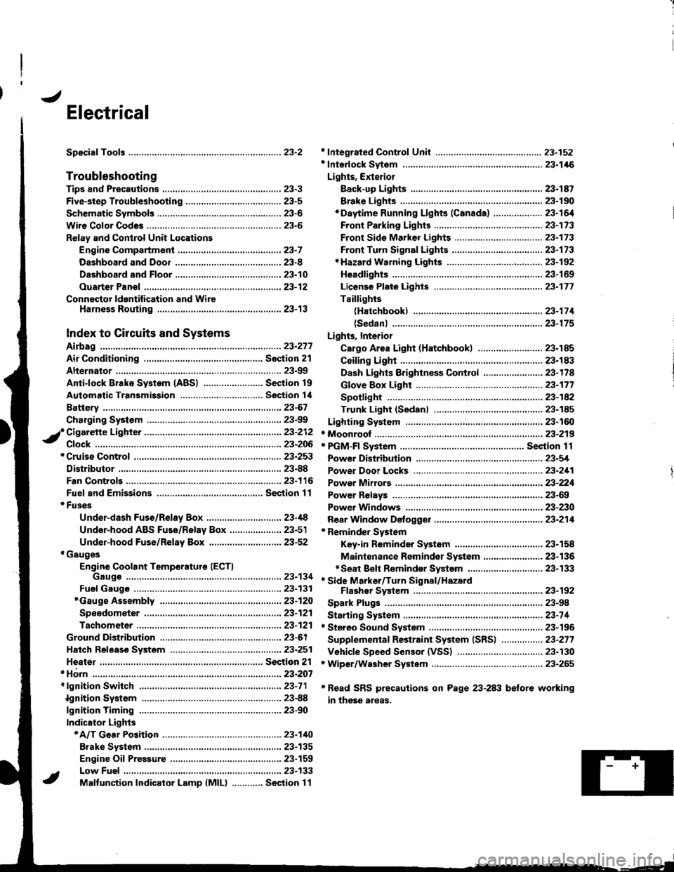
Electrical
Speciaf Toofs ..........................23-2
Troubleshooting
Tips 8nd Precautions .......................,..,.,.,.,.,......,..., 23-3
Five-step Troubleshooting ............,......,.,.,...,..,....., 23-5
Schsmatic Svmbols ...............23-6
Wire Color Code3 .. ................. 23-6
Relay and Control Unit Locations
Engine Compartment ......,.,.................,.,.,.,.,.,,,, 23-7
Dashboard and Door .........,...........,.....,.,....,.,.... 23-8
Dashboard and Floor ......................................... 23-10
Ouarter Pan€f .,,.,...,.,..,...,,,23-12
Connector ldontification and WireHarness Routing ......,.,......23-'13
Index to Circuits and Systems
Airbag
* Integrated Control Unit .....,.,.,.....23-152* Interlock Sytem .,...,.,...........,. 23.146
Lights, Exterior
Eack-up LighB ..................23.187
Brake Ligh$ ......................23-190*Daytime Running Lights (Canada) ................... 23"164
Front Parking Lights .......................................... 23-173
Front Side Marker Lights .................................. 23-173
Front Turn Signal Lights ..................-.......,...,.,. 23-173* Hazard Warning Lights ....................,........,....... 23-192
Headlights.....23-169
23-253 powerDistribution..................... 23-5/r
Air Conditioning.....,....... Soction 21
Alternator ..........,................... 23.99
iCigarette Lighter .........23-212
*Cruise Control
Distributor
'.'.,.'.'.,.'...,,,,.,''.'.,.',.'''.' 23.277
.............................. 23.88
................... 23-90lgnition Timing ......
Indicator Lights
Key-in Reminder System
Maintenance Reminder System*Seat Belt R€mindor System .,...........................* Side Marker/Turn Signal/HazardFlashcr Svstem .................23-192
Spark Plugs ............................23-98
Starting System .....................23-74* Stereo Sound System ...,......,..........,...,......,.,.,.,..,., 23-196
Supplemental Restraint System (SRS) ................ 23-277
Vshicle Speed Sensor (VSS) ................................. 23.130r Wiper/Washer System .........................................., 23-265
*Read SRS precautions on Psge 23-283 before working
in those areas,
23-154
23.136
23"133
Page 1656 of 1681
ng
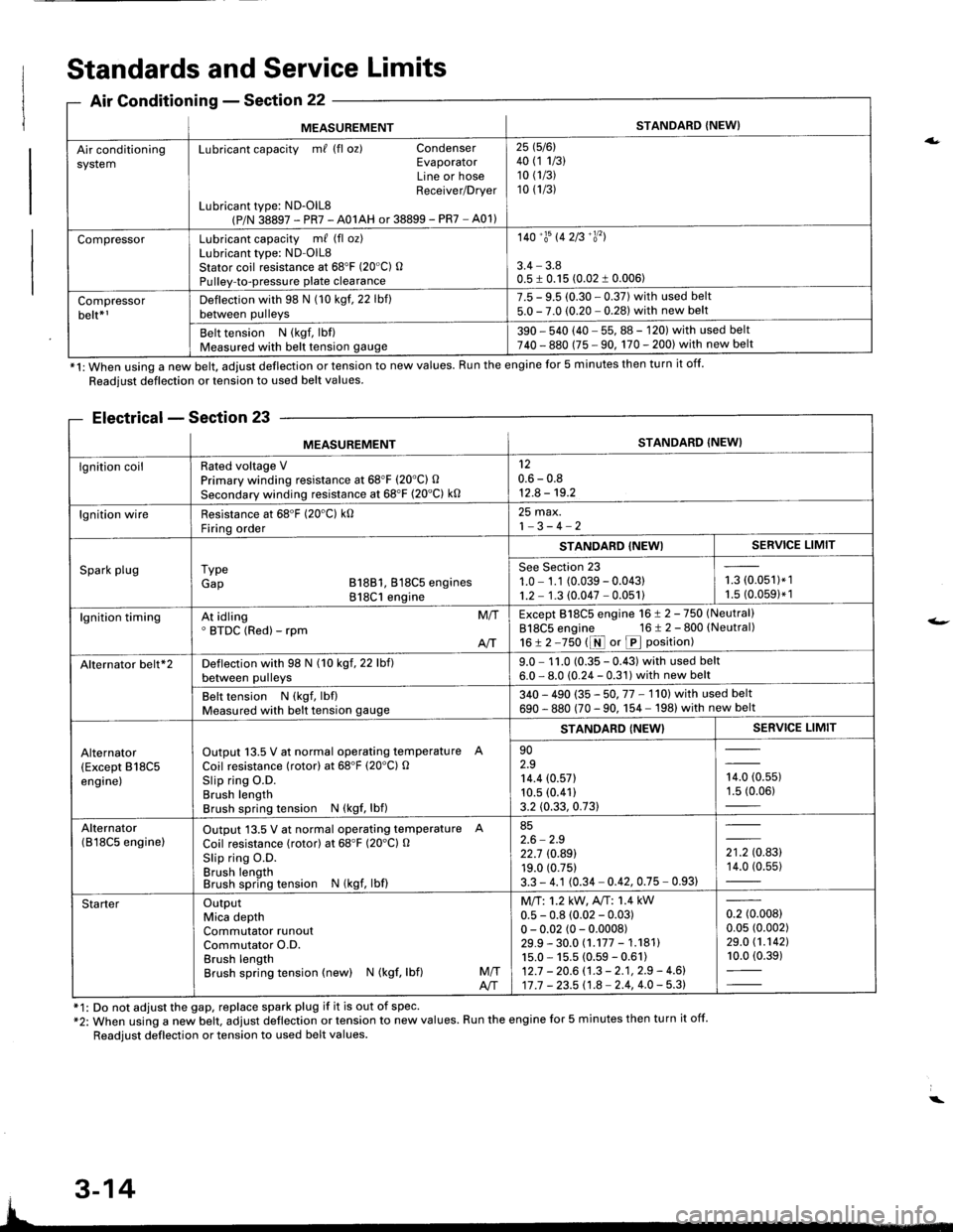
MEASUREMENTSTANDARD {NEW}
Air conditioningsystemLubricant capacity m/ (fl oz) CondenserEvaporatorLine or hoseReceiver/Drver
Lubricant type: ND-OlL8(P/N 38897 - PR7 - A01AH or 38899 - PR7 - A01)
25 1516l40 (1 1/3)10 (1/3)
10 (1/3)
CompressorLubricant capacity m/ (fl oz)Lubricant type: ND-OlL8Stator coil resistance at 68'F (20"C) OPulley-to-pressure plate clearance
140'�trs 142B'�y'�l
3.4 - 3.80.5 I 0.15 (0.02 1 0.006)
Compressorbelt*rDeflection with 98 N (10 kgf. 22 lbf)between pulleys
7.5 - 9.5 (0.30 - 0.37) with used belt5.0 - 7.0 (0.20 - 0.281 with new belt
Belt tension N (kgf, lbf)Measured with belt tension gauge390 - 540 (40 - 55, 88 - 120) with used belt740 - 880 (75 - 90, 170 - 200) with new belt
*1: When using a new belt, adjust deflection or tension to new values. Run the engine for 5 minutes then turn it off.
Standards and Service Limits
Air Conditionins - Section 22
Readjust deflection or tension to used belt values.
Electrical - Section 23
f1: Do not adjust the gap, replace spark plug if it is out of spec'*2: When using a new belt. adjust deflection or tension to new values. Run the engine for 5 minutes then turn it off.
Readjust deflection or tension to used belt values.
a.
t-
MEASUREMENTSTANDARD (NEW}
lgnition coilRated voltage VPrimary winding resistance at 68"F (20'C) O
Secondary winding resistance at 68'F (20"C) k0
120.6 - 0.812.8 - 19.2
lgnition wireResistance at 68'F (20'C) k0Firinq order
25 max.1-3-4-2
Spark plugI ypeGap B18B1, 818C5 engines818C1 engine
STANDABD {NEWISERVICE LIMIT
See Section 231.0 - 1.1 (0.039 - 0.04311.2 - 1.3 (0.047 - 0.051)i-= roru',t.',1.5 (0.0591* 1
lgnition timingAt idling' BTDC (Red) - rpmM/T
AIT
Except 818C5 engine 16 ! 2 -750 (Neutral)
818C5 engine 16 t 2 - 800 (Neutral)
16!2-750 t1r{ or p position)
Alternator belt*2Deflection with 98 N (10 kgf, 22 lbf)between pulleys9.0 - 1 1.0 (0.35 - 0.43) with used belt6.0 - 8.0 (0.24 - 0.31) with new belt
Belt tension N (kgf, lbflMeasured with belt tension gauge340 - 490 (35 - 50. 77 - 1'l0l with used belt
690 - 880 (70 - 90. 1 54 - 198) with new belt
Alternator(Except B18C5engine)
Output 13.5 V at normal operating temperature A
Coil resistance (rotor) at 68'F (20'C) OSlip ring O.D.Brush lengthBrush spring tension N (kgf, lbf)
STANDARD {NEW}SERVICE LIMIT
902.914.4 (0.571
10.5 (0.41)
3.2 (0.33, 0.73)
,0, to.uur1.5 (0.06)
Alternator(B l8C5 enginelOutput 13.5 V at normal operating temperature A
Coil resistance (rotor) at 68"F (20'Cl O
Slip ring O.D.Brush lengthBrush spring tension N (kgf, lbf)
852.6 - 2.922.7 rc.89119.0 (0.75)
3.3 - 4.1 (0.34 - 0.42, 0.75 - 0.93)
',to.tg14.0 (0.55)
StarterOutputMica depthCommutator runoutCommutator O.D.Brush lengthBrush spring tension (new) N (kgf, lbf)M/TA/T
Mll:1.2 kW, A"rT: 1.4 kW0.5 - 0.8 (0.02 - 0.03)0 - 0.02 (0 - 0.0008)29.9 - 30.0 (.177 - 1.18111s.0 - 15.5 (0.59 - 0.61)12.7 - 20.6 (.3 - 2.1, 2.9 - 4.6)17 .7 - 23.5 11.8 - 2.4, 4.0 - 5.3)
0.2 (0.008)
0.05 (0.002)
29.0 (1.1421
10.0 (0.39)
3-14