differential HONDA INTEGRA 1998 4.G Workshop Manual
[x] Cancel search | Manufacturer: HONDA, Model Year: 1998, Model line: INTEGRA, Model: HONDA INTEGRA 1998 4.GPages: 1681, PDF Size: 54.22 MB
Page 52 of 1681
Engine Removal/lnstallation
(cont'dl
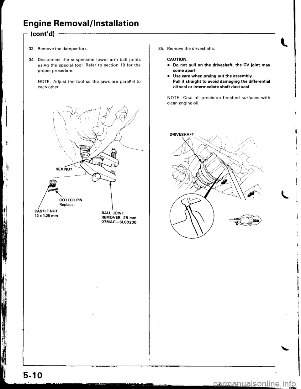
34.
Remove the damper {ork.
Disconnect the suspension lower arm ball joints
using the special tool. Refer to section '18 for the
proper procedure.
NOTE: Adjust the tool so the jaws are parallel to
each other.
12 x 1.25 mm
5-jl0
\
35. Remove the driveshafts.
CAUTION:
. Do not pull on the driveshaft, the CV joint may
come aoart.
. Use care when prying out the assembly.
Pull it straight to avoid damaging the differential
oil seal or intermediate shaft dust seal.
NOTE: Coat all precision Iinished surfaces with
clean enoine oil.
,{:
DRIVESHAFT/.-:
/
Page 357 of 1681
Transaxle
Clutch ...........12-1
Manual Transmission ............................ 13-1
Automatic Transmission ....................... 1 4-1
Differential
Manual Transmission
B1881 engine ................................... 15-1
818C1 engine ................................... 15-9
B18C5 engine .............. 15-19
Automatic Transmission ................. .. 15-27
Driveshafts ... 16-1
Page 383 of 1681
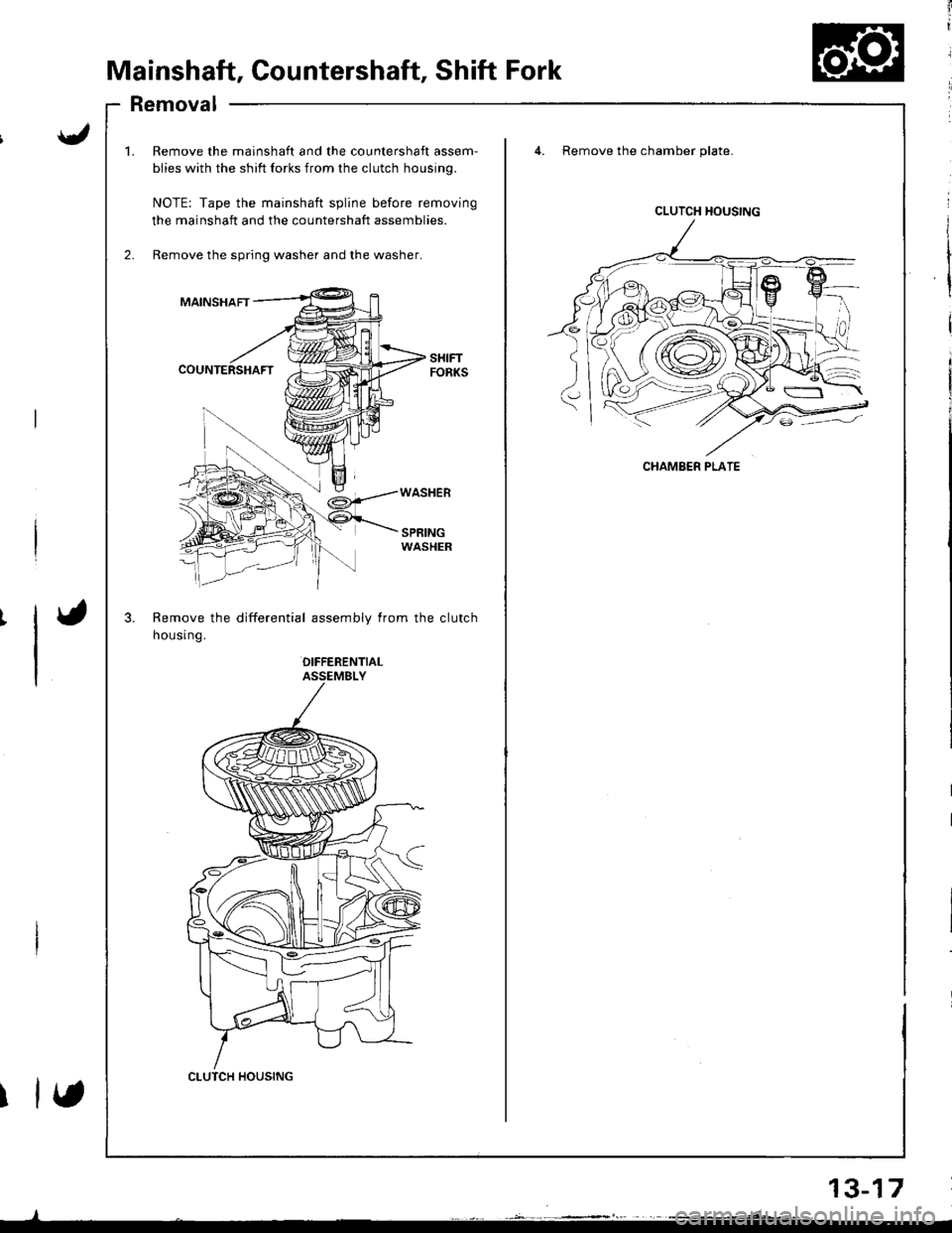
Mainshaft, Countershaft, Shift Fork
Removal
mainshaft and the countershaft assem-
? shift forks from the clutch housing.
the mainshaft spline before removing
ft and the countershaft assemblies.
spring washer and the washer.
differential assembly from the clutch
OIFFERENTIALASSEMBLY
4. Remove the chamber plate.
SPRINGWASHER
1.Remove the m€
biies with the sl
NOTE: Tape th
the mainshaft a
Remove the spr
MAINSHAFT
COUNTERSHAFT
Remove the
housr ng.
CLUTCH HOUSING
CLUTCH HOUSING
CHAMBER PLATE
etsY')
2r}5
(\cyl,//_\::iv/.
13-17
Page 407 of 1681
I
t
\
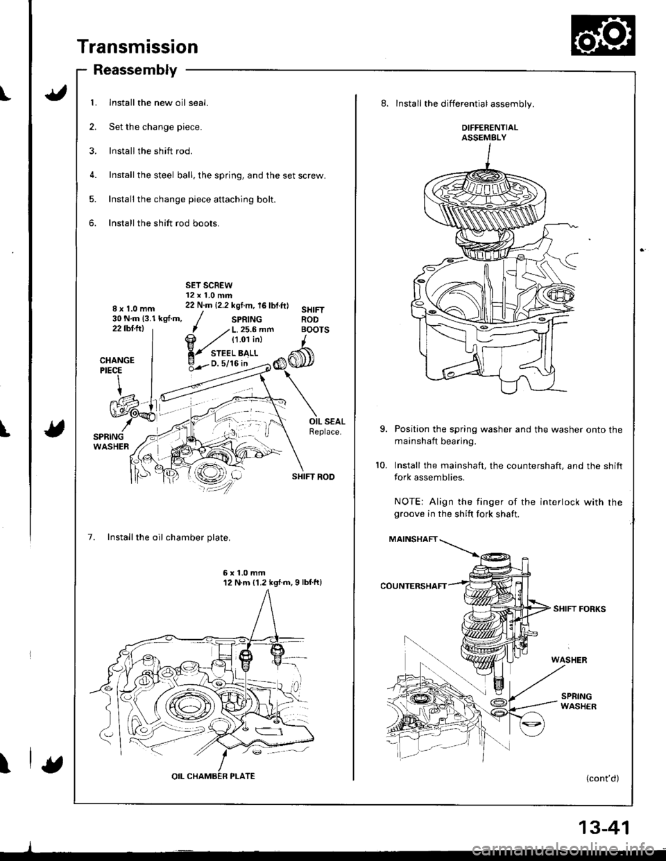
Transmission
Reassembly
1. Install the new oil seal.
2. Set the change piece.
3. lnstall the shift rod.
4. Install the steel ball, the spring, and the set screw.
5. Install the change piece attaching bolt.
6. Install the shift rod boots.
8x1.0mm30 N.m (3.1 kgf.m,22tbfitl
SHIFT ROD
7. Installthe oil chamber plate.
7 .' L. 25.6 mfi BOI
@ ,zt tt.o'ti"t I
Y-",:'b>,",CI
6x1.0mm12 N.m {1.2 kgl.m,9 lbf.ft)
8. Install the differential assembly.
DIFFERENTIALASSEMBLY
Position the spring washer and the washer onto the
mainshaft bearing.
Install the mainshaft, the countershaft. and the shift
fork assemblies.
NOTE: Align the finger of the interlock with rhegroove in the shift fork shaft.
MAINSHAFT
SHIFT FORKS
(cont'd)
10.
13-41
Page 424 of 1681
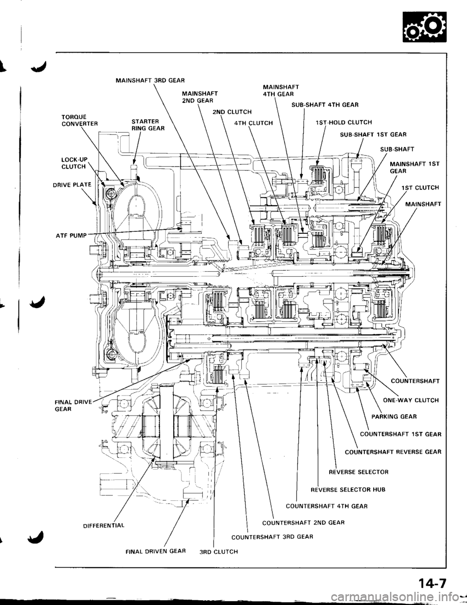
I
2NO CLUTCHSUB-SHAFT 4TH GEAR
1ST HOLO CLUTCH
SUB SHAFT 1ST GEAE
SUB,SHAFT
MAINSHAFT 1ST
CLUTCH
MAINSHAFT
COUNTERSHAFT
ONE.WAY CLUTCH
PARKING GEAR
COUNTERSHAFT 1ST GEAR
COUNTERSHAFT REVERSE GEAR
REVERSE SELECTOR
SELECTOR HUB
TOROUE4TH CLUTCH
LOCK-UPCLUTCH
DRIVE PLATE
ATF PUMP
COUNTERSHAFT 4TH GEAR
DIFFERENTIALCOUNTERSHAFT 2ND GEAR
COUNIERSHAFT 3RD GEAR
FINAL DRIVEN GEAR3RD CLUTCH
14-7
MAINSHAFT 3RD GEAR
Page 510 of 1681
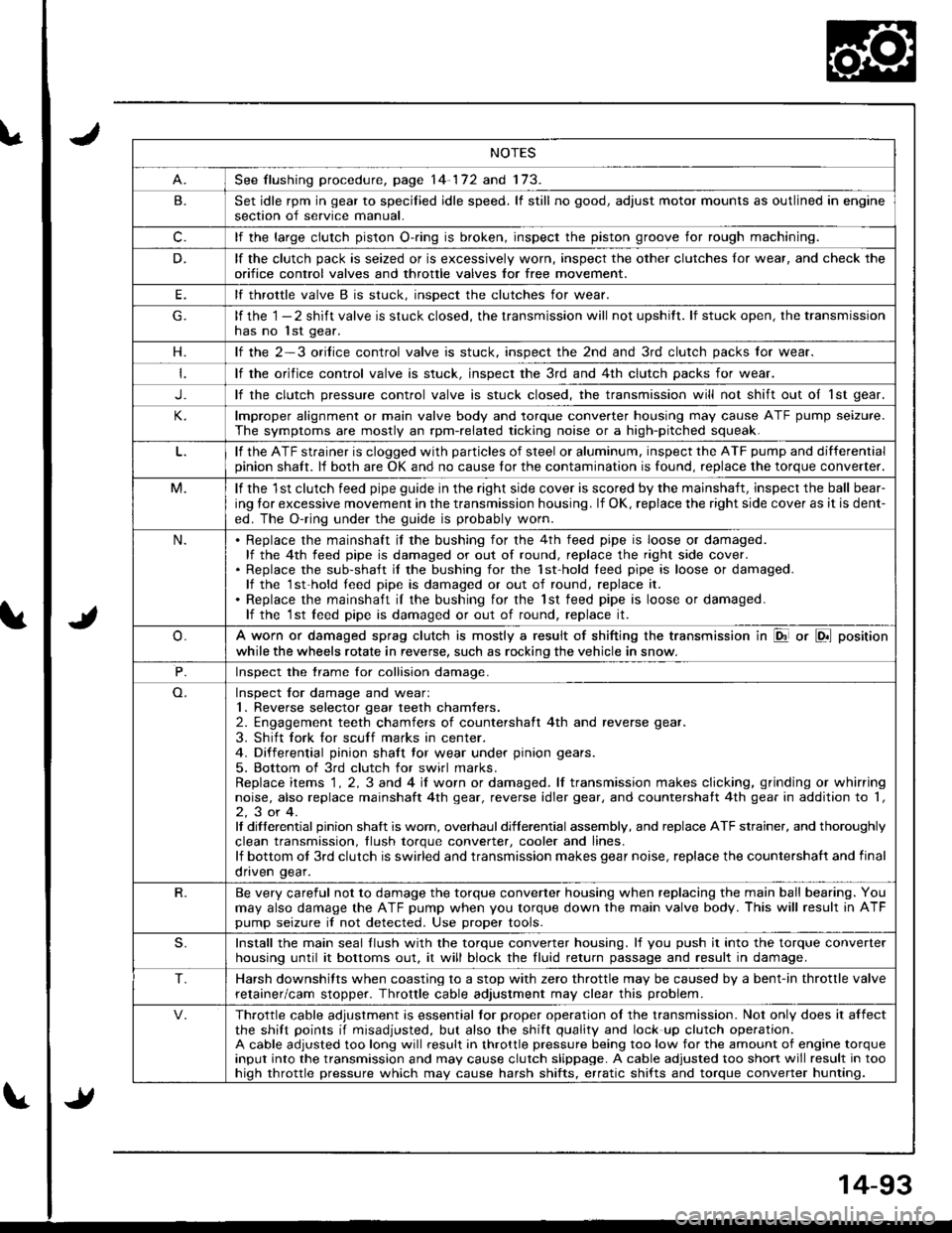
NOTES
See flushing procedure, page 14-172 and 173.
B.Set idle rpm in gear to specilied idle speed. lf still no good, adjust motor mounts as outlined in enginesection of service manual.
c.lf the large clutch piston O-.ing is broken, inspect the piston groove for rough machining.
D.lf the clutch pack is seized or is excessively worn, inspect the other clutches lor wear, and check the
orifice control valves and throttle valves for free mov€ment.
E.lf throttle valve B is stuck. insDect the clutches for wear.
lf the 1 - 2 shift valve is stuck closed, the transmission will not upshitt. lf stuck open, the transmissionhas no lst gear.
H.lf the 2-3 orilice control valve is stuck, inspect the 2nd and 3rd clutch packs for wear.
lf the orifice control valve is stuck. inspect the 3rd and 4th clutch packs for wear.
J.lf the clutch pressure control valve is stuck closed, the transmission will not shift out oI 1st gear.
lmproper alignment or main valve body and torque converter housing may cause ATF pump seizure.
The symptoms are mostly an rpm-related ticking noise or a high-pitched squeak.
lf the ATF strainer is clogged with particles of steel or aluminum, inspect the ATF pump and differentialpinion shaft. lf both are OK and no cause for the contamination is found, replace the torque converter.
M.lf the 1st clutch feed pipe guide in the right side cover is scored by the mainshaft, inspect the ball bear-
ing lor excessive movement in the transmission housing. lf OK, replace the right side cover as it is dent-
ed. The O-ring under the guide is probably worn.
N.Replace the mainshaft if the bushing for the 4th feed pipe is loose or damaged.lf the 4th feed pipe is damaged or out of round, replace the right side cover.Replace the sub-shaft il the bushing for the 1st-hold teed pipe is loose or damaged.lf the 1st-hold teed pipe is damaged or out of round, replace it.
Replace the mainshaft iI the bushing for the lst feed pipe is loose or damaged.lf the 1st leed pipe is damaged or out of round, replace it.
A worn or damaged sprag clutch is mostly a result of shifting the transmission in El or LDll position
while the wheels rotate in reverse, such as rocking the vehicle in snow.
P.Inspect the trame for collision damage.
Inspect lor damage and wear:1. Reverse selector gear teeth chamfers.2. Engagement teeth chamfers of countershaft 4th and reverse gear.
3. Shift fork for scuff marks in center.4. Differential pinion shaft tor wear under pinion gears.
5. Bottom of 3rd clutch for swirl marks.Replace items 1 . 2, 3 and 4 iI worn or damaged. lf transmission makes clicking, grinding or whirringnoise, also replace mainshaft 4th gear, reverse idler gear, and countershatt 4th gear in addition to '1,
2,3or4.It differential pinion shalt is worn, overhaul differential assembly, and replace ATF strainer, and thoroughly
clean transmission, tlush torque conveder, cooler and lines.lf bottom ot 3rd clutch is swirled and transmission makes gear noise, replace the countershaft and final
onven qear.
R.Be very careful not to damage the torque converter housing when replacing the main ball bearing. You
may also damage the ATF pump when you torque down the main valve body. This will result in ATFpump seizure if not detected. Use proper tools.
S.Install the main seal llush with the torque converter housing. lf you push it into the torque converterhousing until it bottoms out. it will block the fluid return passage and result in damage.
T.Harsh downshifts when coasting to a stop with zero throttle may be caused by a bent-in throttle valve
retainer/cam stopper. Throttle cable adjustment may clear this problem.
Throttle cable adjustment is essential tor proper operation ol the transmission. Not only does it affectthe shift points if misadjusted, but also the shift quality and lock up clutch operation.A cable adjusted too long will result in throttle pressure being too low for the amount of engine torqueinput into the transmission and may cause clutch slippage. A cable adjusted too short will result in toohiqh throttle pressure which may cause harsh shifts, erratic shifts and torque converter hunting.
Page 523 of 1681
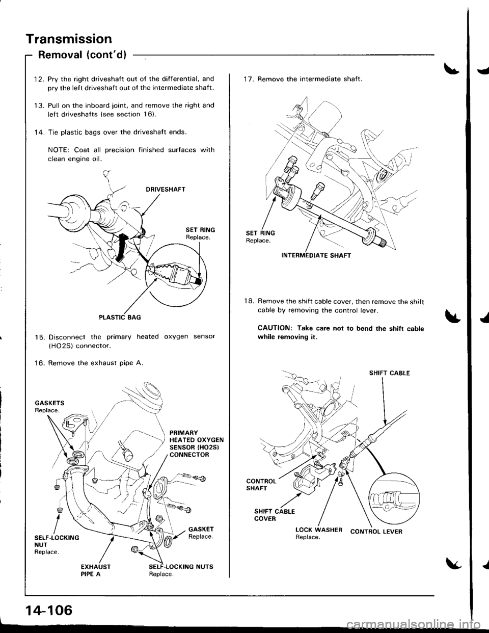
Transmission
Removal (cont'd)
'12. Pry the right driveshaft out of the differential, and
pry the lelt driveshaft out ol the intermediate shaft.
13. Pull on the inboard joint, and remove the right and
lelt driveshatts (see section l6).
14. Tie plastic bags over the driveshalt ends.
NOTE: Coat all precision finished surlaces with
clean engine oil.
Disconnect the primary heated oxygen sensor
(HO2S) connector.
Remove the exhaust pipe A.
| 5.
to.
PRIMARYHEATEO OXYGENSENSOR {HO25lCONNECTOR
SELF-LOCKINGNUTReplace.
14-106
J
J
.l
18.
'17. Remove the intermediate shaft.
Remove the shitt cable cover, then remove the shilt
cable by removing the control lever.
CAUTION: Take care not to bend the shifr cablewhile removing it.
CONTROL LEVER
INTERMEDIATE SHAFT
SHIFT CABLE
Page 528 of 1681
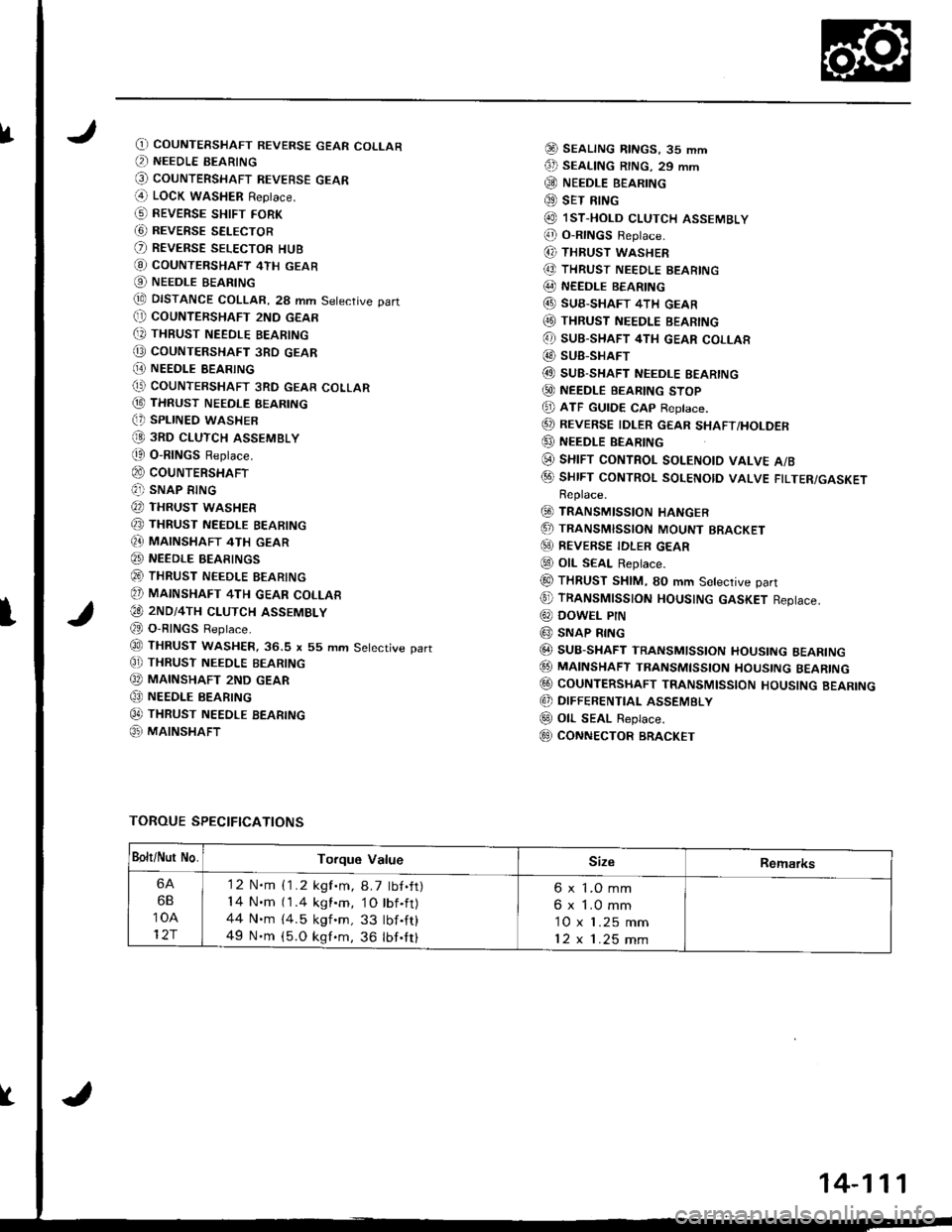
fO) COUNTERSHAFT REVERSE GEAR COLLAR(, NEEDLE BEARING
@ couNTERSHAFT REVEBsE GEAR(4 LOCK waSHER Replace.
G) REVERSE sHtFr FoRK
G) REVERSE SELECTOR
O REVERSE SELEcToR HUB
@ coUNTERSHAFT 4TH GEAR
O NEEDLE BEARING
tE DISTANCE COLLAR, 28 mm Setective part(} COUNTERSHAFT 2ND GEAR
[, THBUST NEEDLE BEARING
@ coUNTERSHAFT 3RD GEAR
[E NEEDI.E BEARING(' COUNTERSHAFT 3RD GEAR COLLAR
@ THRUST NEEDLE BEARING(, SPLINED WASHER
@ 3RD cLUTcH ASSEMBLY
t0 O-RINGS Replace.
@ couNTERSHAFT(?]) SNAP RING
@ THRUST WASHER
@ THRUST NEEDLE BEARING
Q} MAINSHAFT 4TH GEAR
@ NEEDLE BEARINGS
@ THRUST NEEDLE BEARING
@ MAINSHAFT 4TH GEAR coLLAR
€O 2ND/4TH cLUTcH ASSEMBLY
@ O-RINGS Reptace.
@ THRUST WASHER.36.S x 55 mm Setective part
C]) THRUST NEEoLE BEARING
@ MAINSHAFT 2ND GEAR
@ NEEDLE BEARING
0t THRUST NEEDLE BEARTNG
@ MAINSHAFT
@ SEALTNG RtNGs, 35 mm
€D SEAL|NG R|NG. 29 mm
@ NEEDLE B€ARING
@ sET RING
@ lsT.HoLD cLUTCH ASSEMBLY
@ o-RtNGs Reptace.
(, THRUST WASHER
@ THRUST NEEDLE BEARING
@ NEEDLE BEARING
@ SUB-SHAFT 4TH GEAR(O THRUST NEEDLE BEARING
@ sUB-SHAFT 4TH GEAR coLLAR
@ SUB-SHAFT
@ SUB-SHAFT NEEDLE EEARING
@ NEEDLE BEARTNG sToP
@ ATF GUTDE cAp Reptace.
@ REVERSE IDLER GEAR sHAFT/HoLDER
@ NEEDLE BEARING
(i) sHrFT coNTRoL soLENotD vALvE A/B
@ sHrFT coNTRoL soLENotD vALVE FTLTER/GASKETReplace.
@ TRANSMISSIoN HANGER
.5, TRANSMISSIoN MoUNT BRACKET
@) REVERSE TDLER GEAR
@ otL SEAL Replace.
@ THRUST SHIM, SO mm Setective part
@ TRANSMTSSTON HOUSTNG GASKET Reptace.
@ DowEL PtN
@ SNAP RING
@ SUB-SHAFT TRANSMlsstoN HoustNG BEARTNG
@ MA|NSHAFT TRANsMtssroN HoustNG BEARTNG
@ CoUNTERSHAFT TRANSMIssloN HoUsING BEARING
@ DIFFERENTIAL ASSEMBLY
@ oll- SEAL Replace.
E9 CONNECTOR BRACKET
TOROUE SPECIFICATIONS
I
Bolt/Nur No.Torque ValueSizeRemarks
6A
6B
10A
12r
'12 N.m {1.2 kgf.m, 8.7 tbf.ft)14 N.m (1.4 kgl.m, 1O tbf.ft)44 N.m {4.5 kgf 'm, 33 tbf .ft}
49 N.m (5.O kgf.m, 36 lbf.tt)
6 x 1.O mm
6 x 1.0 mm
10 x 1.25 mm
12x1.25mm
14-111
Page 533 of 1681
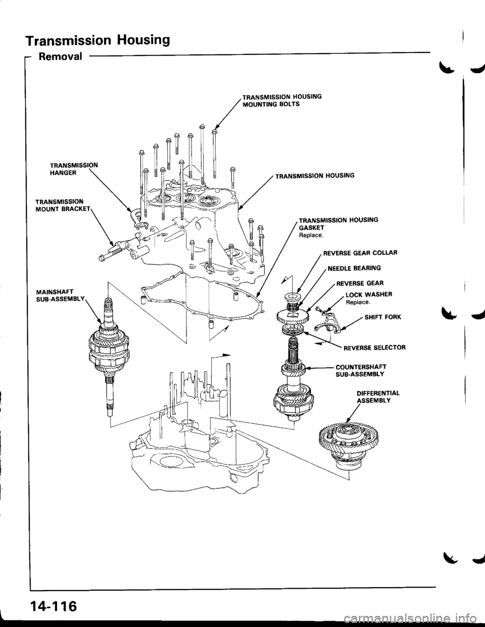
Transmission Housing
Removal
J
TRANSMISSION HOUSING
MOUNTING BOLTS
TRANSMISSION HOUSING
TRANSMISSION HOUSING
GASKETReplace.
REVERSE GEAR COLLAB
NEEDLE BEARING
REVERSE GEAR
MAINSHAFTSU8-ASSEMBLY
, 14-116
LOCX WASITEFReplace.
4
REVERSE SELECTOR
COUNTERSHAFTSUB.ASSEMELY
DIFFERENTIALASSEMBLY
J
Page 534 of 1681
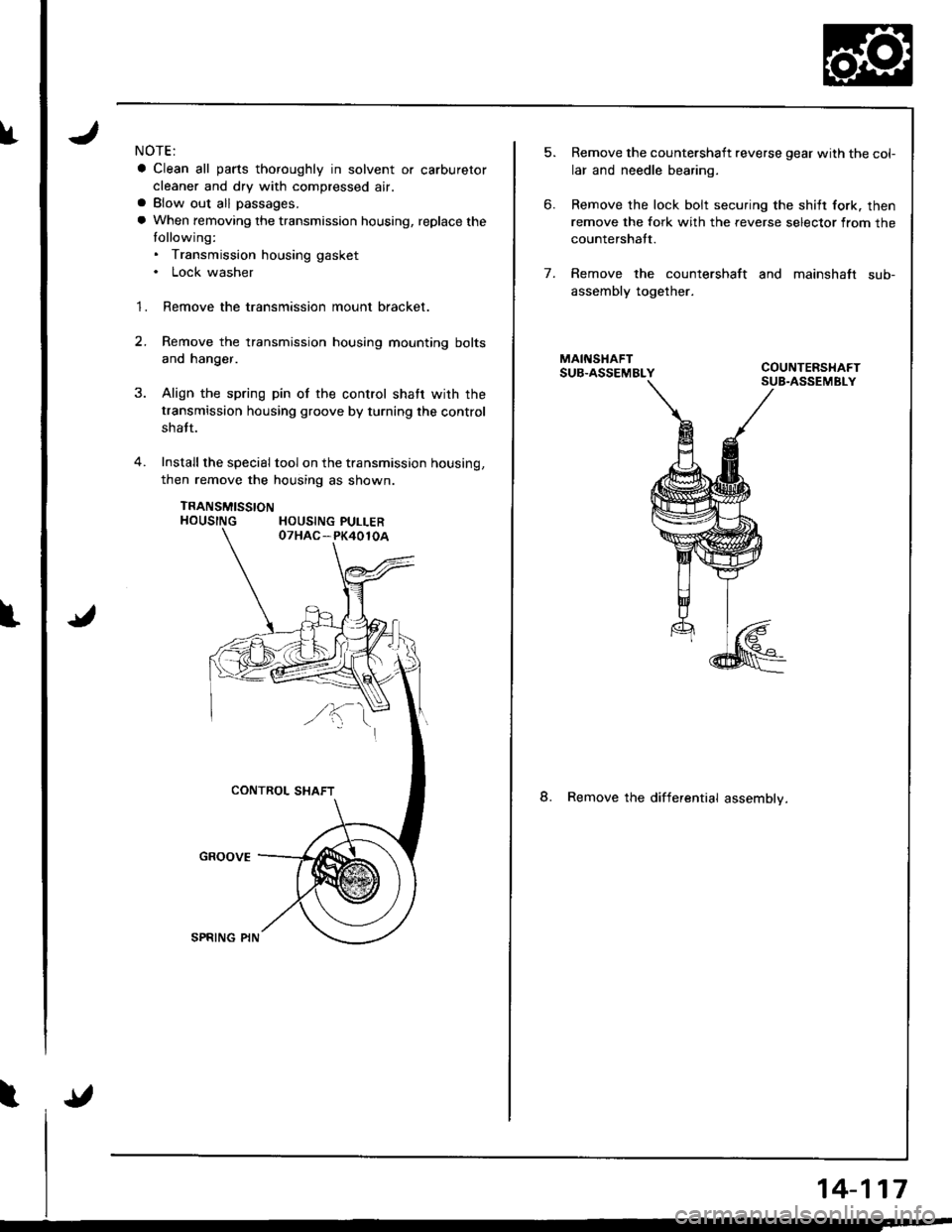
fNOTE:
a Clean all parts thoroughly in solvent or carburetor
cleaner and dry with compressed air.a Blow out all passages.
a When removing the transmission housing, replace the
tollowing:. Transmission housing gasket. Lock washer
1. Remove the transmission mount bracket.
2.Remove the transmission housing mounting bolts
and hanger.
Align the spring pin of the control shatr wirh the
transmission housing groove by turning the control
shatt.
Install the special tool on the transmission housing,
then remove the housing as shown.
TRANSMISSTONHOUSING HOUSING PULLER
5.
6.
Remove the countershaft reverse gear with the col-
lar and needle bearing.
Remove the lock bolt securing the shilt fork. then
remove the fork with the reverse selector from the
countershatt.
Remove the countershaft and mainshaft sub-
assembly together.
8. Remove the differential assemblv.
7.
14-117