steering wheel adjustment HONDA INTEGRA 1998 4.G Workshop Manual
[x] Cancel search | Manufacturer: HONDA, Model Year: 1998, Model line: INTEGRA, Model: HONDA INTEGRA 1998 4.GPages: 1681, PDF Size: 54.22 MB
Page 652 of 1681
I
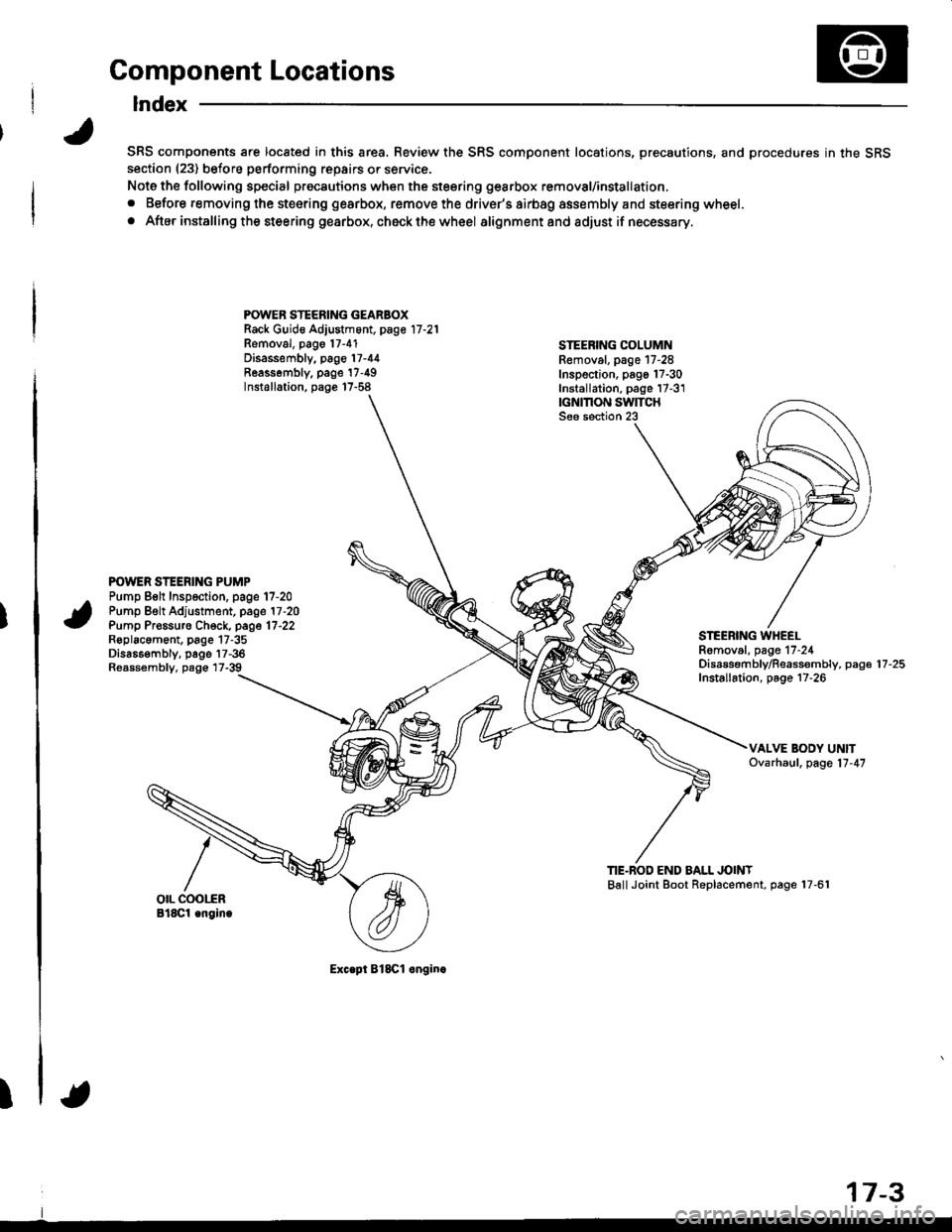
Component Locations
Index
SRS components are located in this area. Review the SRS component locations, precautions, and procedures in the SRSsection (23) before performing repairs or service.
Note the following special precautions when the steering gearbox removal/installation,
. Before removing the steering gearbox, remove the driver's airbag assembly and steering wheel.
. After installing the steering gearbox, ch6ck the wheel alignmentand adjust if necessary.
POWER STEERING GEARBOXRack Guid€ Adjustment, page 17 -21
Removal, pago 17-4'1Disassembly, page 17-44Reassombly. page'17-49Installation, page 17-58
STEEBING COLUMNRemoval. page 17-28Inspection, pago 17-30Installation, page 17-3'1|GNMON SWITCHSee section 23
POWER STEERING PUMPPump Belt Inspection. page 17-20Pump Belt Adjustment, page 17 -20
Pump Pr€ssuro Check, page 17'22Roplacament, page 17-35Dis686embly, page 17-36Reassembly, page 17-39
STEEBING WHEELRomoval, page 17-24Disassembf y/Reassembly, paga 17 -25
Installation, page 17-26
TIE.BOD END BALL JOINTBallJoint Boot Replacement, page 17-61
Exc.pt BlSCl onginc
17-3
Page 660 of 1681
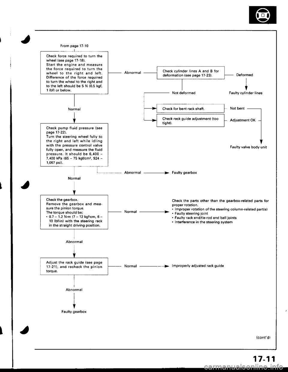
From page 17-10
Normal
Check lorce required to turn thewhool (see page 17-'18).Start the engine and measu16the force required to turn thewheel to the right and left.Difference of the force requiredto twn the wheel to the right andto the left should be 5 N (0.5 kgf,1 lbl) or below.
Deformed
I
iFaulty cylinder lines
Not bent
Adjustment OK
Faulty valve body unit
Abnormal --> Faulty gearbox
Ch€ck th6 pans other than the gearbox-related parts lorDrooer rolaton.
. . lmproper rotation ofthe steering column-related pan{s}----------------- . tau[y $eenng lornt. Faulty rack endtio-rod ond balljoints. Intgrferonce in the steering system
Normal -----> lmproperly adjusted rack guide
Check lor bent rack shaft.
Check pump fluid pressure (seepage 17-22).Turn the steoring wheel fully tothe right and l€ft while idlingwilh the pressure control valveIully open, and measure the Iluidpressure. lt should be 6,400 -
7,400 kPa (65 - 75 kgflcmr, 924 -
1,067 psi).
Normal
Ch€ck the gearbox.Remove the gearbox and mea-sure the pinion torque.The lorque should be;. 0.7 - '1.2 N.m (7 - 12 kgf.cm, 6 -
10 lbf.in) wjth the steering rackin the straight driving position.
Abnormal
Adjust the rack guide {see page17-211, and recheck the pinion
torque.
17-11
Page 661 of 1681
Troubleshooting
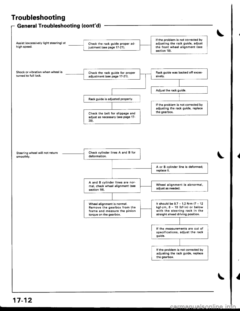
General Troubleshooting (cont'dl
Assist (excessively light steering) athigh speod.
Shock or vibration when wheel isturned to full lock.
Steering wheel will not return
smoothly.
a-, aa GrI r- tz
ll the problom is not correcled byadiusting the rack guide, adjustthe front wh66l alignment (see
s6ction 18).
Ch6ck th6 rack guide propgr ad-justment (see pago 17-21).
Check the rack guido lor proper
adjustment (see page 17-21).
Rack guid€ is adjusted properly.
lf the problem is not corrected byadjusting the rack guide, replscothe gearbox.Check the belt for slippage andadjust as nec€ssary {s6e page 17-20).
A and B cylinder lines are nor-mal, chgck wheol alignment (se€
section 18).
Whe6l alignment is abnormal,adjust as needod.
It should be 0.7 - 1.2 N.m {7 - 12kgl.cm.6 - 10 lbf.in) or belowwith the steering rack in thestraight ahoad driving position.
wh€el alignment is normal.R€mov€ the gearbox from thofram6 snd measure the pinion
torque on the gearbox.
lf the measurements are out ofsp€cifications. adjust the rackgurd9.
It the problom is not corrected byadiusting the rack guido. r€placethe goarbox.
{
I
Page 663 of 1681
I
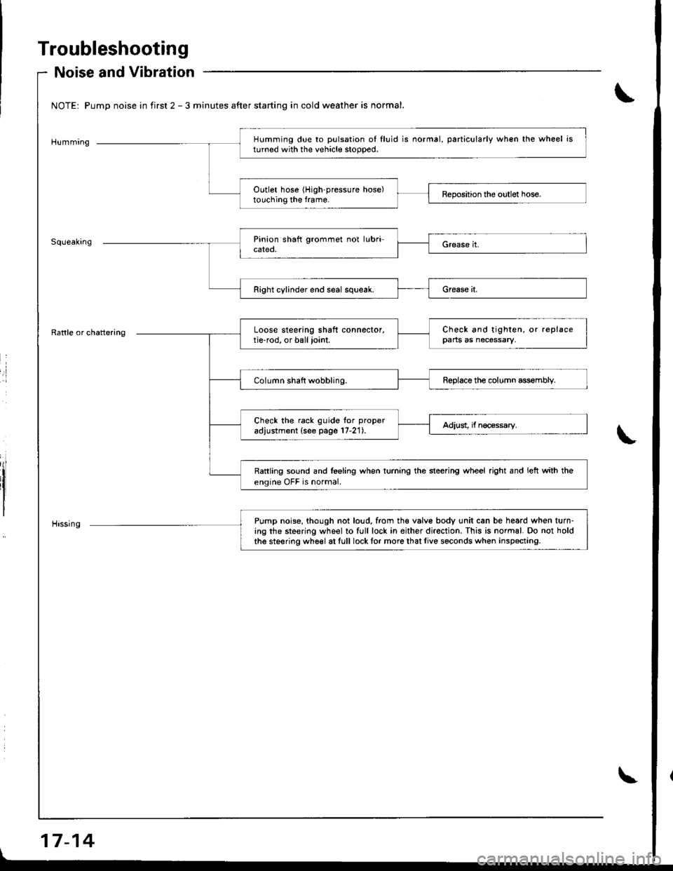
Troubleshooting
17-14
Noise and Vibration
NOTEr Pump noise in first 2 - 3 minutes after starting in cold weather is normal.
Humming
Rattle or chattering
Humming due to pulsation oI lluid is normal, particularly when the wheel isturned with the vehicle stoooed.
Outlet hose (High-pressure hose)touching the frame.
Right cylinder end seal squeak.
Pump noise, though not loud, from tho valv6 body unit can be heard when turn-ing the steering wheel to full lock in either direction. This is normal. Do not hold
the steering wh6el at tull lock tor more that live seconds wh€n inspecting.
Loose steering shaft connector,tie-rod, or ball ioint.
Check and tighten, or replacepans as necessary,
Column shaft wobbling.Reolace the column assemblv.
Check ihe rack guide tor proper
adjustment (see page 17-21).Adiust, if nec€ssary.
Rattling sound and feeling when turning the steering wheel right and left with the
engine OFF is normal.
Page 667 of 1681
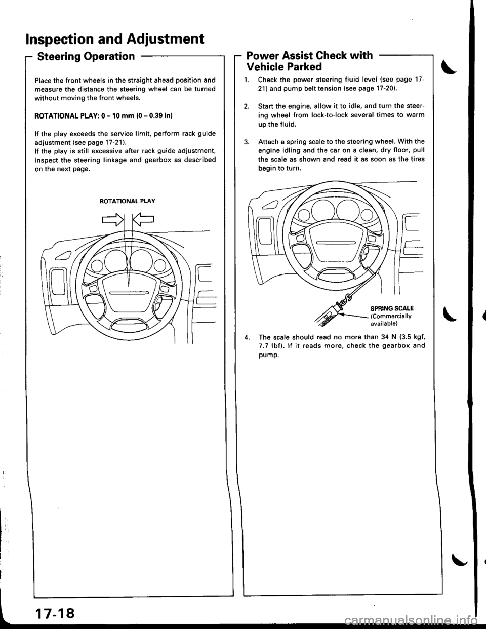
Inspection and Adjustment
Steering Operation
Place the front wheels in the straight ahead position and
measure the distance the steering wheel can be turned
without moving the front wheels.
ROTATIONAL PLAY: 0 - 10 mm {0 - 0.39 inl
lf the play exceeds the service limit. perform rack guide
adiustment (see page 17-211.
lf the play is still excessive after rack guide adjustment.
inspect the steering linkage and gearbox as described
on the neld page.
Power Assist Check with
Vehicle Parked
Check the power steering fluid level (see page 17-
21) and pump belt tension (see page 17-201.
Start the engine, allow it to idle. and turn the steer
ing wheel from lock-to-lock several times to warm
up the fluid.
Attach a spring scale to the steering wheel. With the
engine idling and the car on a clean. dry floor. pull
the scale as shown and read it as soon as the tires
begin to turn,
4. The scale should read no more than 34 N (3.5 kgf,
7.7 lbf). lf it reads more, check the gearbox and
pump.
ROTATIONAL PLAY
Page 669 of 1681
Inspection and Adjustment
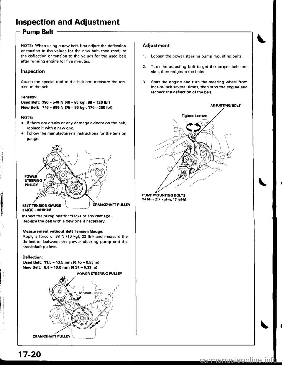
Pump Belt
NOTE: When using a new belt, first adjust the deflection
or tension to the values for the new belt, then readjust
the deflection or tension to the values for the used belt
after running engine for five minutes,
Inspection
Attach the soecial tool to the belt and measure the ten-
sion of the belt.
Tension:
Usad Belt: 390 - 54O N {/10 - 55 kgf. 88 - 120 lbf}
Nsw Belt: 740 - 880 N {75 - 90 kgf. 170-2(X)lbf)
NOTE:
. lf there are cracks or any damage evident on the belt,
replace it with a new one.
. Follow the manufacturer's instructions for the tension
gauge.
ii
:i
i
I
,;h
,lt l
I
i
CRANKSHAFT PULEYBELT TENSION GAUGE07JGG - 001010A
Inspect the pump belt for cracks or any damage.
Replace the belt with a new one if necessary.
Mea3urement without Bah Tonsion Gaugo:
Apply a force of 98 N {10 kgt,22 lbll and measure the
deflection between the power steering pump and the
crankshaft pulleys,
Drllection:
Us.d B6h: 11.5 - 13.5 mm (0.45 - 0.53 in)
New Bsh: 8.0 - 10.0 mm 10.31 - 0.39 inl
POWER STEERING PULLEY
17-20
Adiustment
1. Loosen the power steering pump mounting bolts.
2. Turn the adjusting bolt to get the proper belt ten-
sion, then retighten the bolts.
3. Stan the engine and turn the steering wheel from
lock-to-lock several times. then stop the engine and
recheck the deflection of the belt.
24 N.m l2.a kgf.m, 17 lbf.ftl
Page 670 of 1681
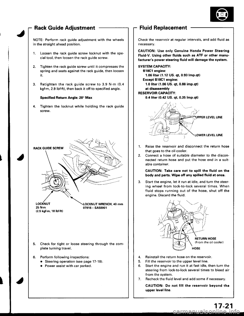
Rack Guide AdjustmentFluid Replacement
Check the reservoir at regular intervals, and add fluid as
neceSsary.
CAUTION: Use only Genuine Honda Powel Ste€ring
Fluid-V. Using other fluids such as ATF or othor manu-
laclurer's power ste€ring fluid will damag€ the systom.
SYSTEM CAPACIW:
B18Gl ongine:
1.06lit€r (1.12 US. qt,0.93 lmp.qt)
Excopt 8l8Cl ongino:
1.0 lher (r.06 US. qt.0.88 imp.qtl
at disa$ombly
RESERVOIR CAPACITY:
0.,0 liter {0.42 US. qt, 0.35 lmp.qt}
LEVEL LINE
LEVEL LINE
Raise the reservoir and disconnect the return hose
that goes to the oil cooler.
Connect a hose of suitable diameter to the discon-
nected return hose and put the hose end in a suit-
able container.
CAUTION: Take care not to spill thq fluid on lhe
body and parts. Wipe off any spilled fluid al onc€.
Start the engine. let it run at idle, and turn the steer-
ing wheel from lock-to-lock several times. When
fluid stops running out of the hose, shut off the
engine. Discard the fluid.
2.
RETURN HOSE{From the oilcooler)
4. Reinstallthe return hose on the reservoir.
5. Fill the reservoir to the uDDer level line.
6. Start the engine and run it at fast idle, then turn the
steering from lock-to-lock several times to bleed air
from the system,
7. Recheck the fluid level and add some it necessary.
CAUTION: Do not lill the reservoir boyond thc
upper level line.
J.
4.
NOTE: Perform rack guide adjustment with the wheels
in the straight ahead position.
1. Loosen the rack guide screw locknut with the spe-
cialtool, then loosen the rack guide screw.
Tighten the rack guide screw until it compresses the
spring and seats against the rack guide, then loosen
it.
Retighten ihe rack guide screw to 3.9 N.m (0.4
kgf.m, 2.9 lbi.ft), then back it ofl to specified angle.
Speciliad Roturn Anglo: 20' Max
Tighten th€ locknut while holding the rack guide
screw.
RACK GUIDE SCREW
25Nm{2.5 kgf.m, 18 lbf ft)
LOCKNUT WRENCH. ilo mm079't 6 - SA50001
E
6.
Check for tight or loose steering through the com-
plete turning travel.
Perform following inspections:
. Steering operation (see page 17-18).
a Power assist with car parked.
I
Page 671 of 1681
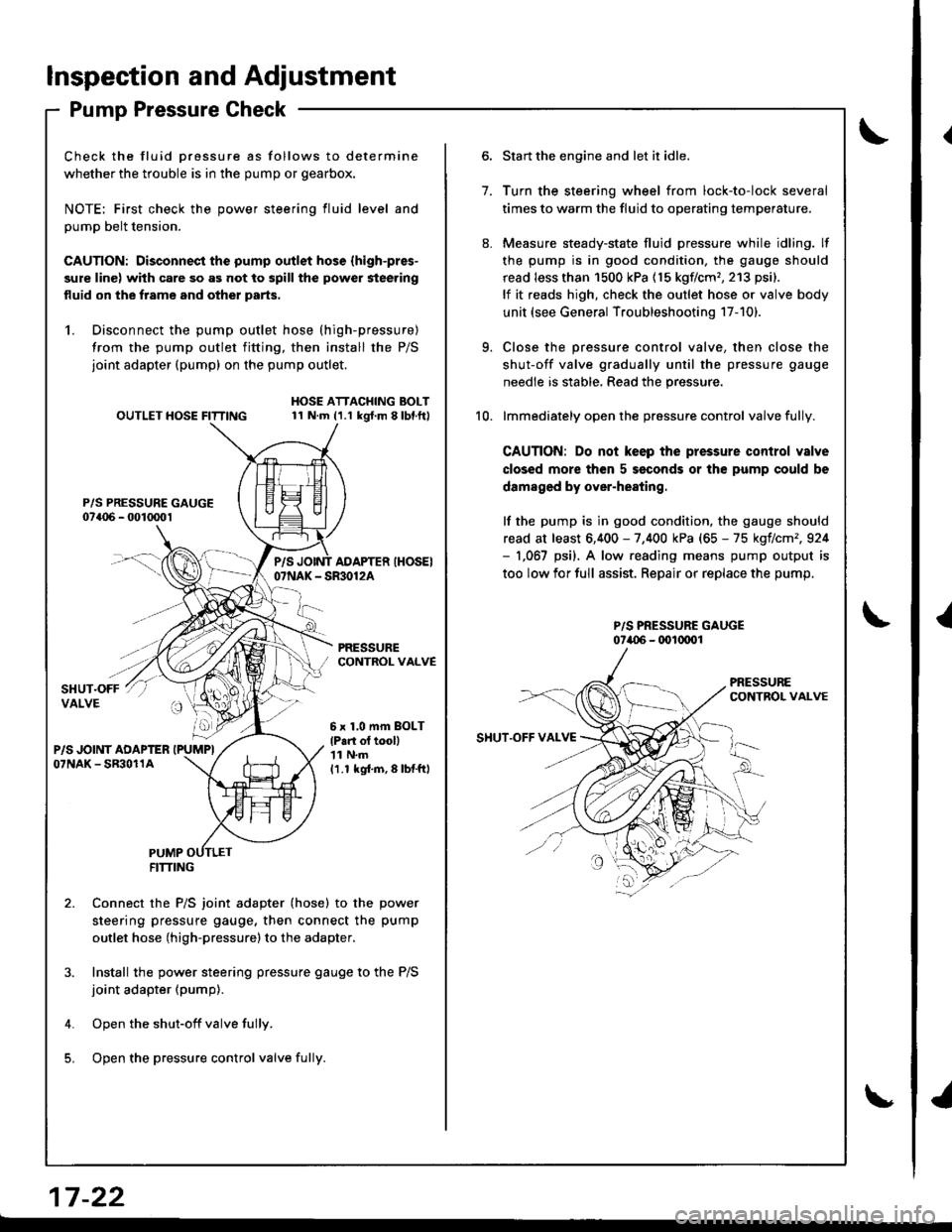
Inspection and Adjustment
Pump Pressure Check
Check the fluid Dressure as follows to determine
whether the trouble is in the pump or gearbox.
NOTE; First check the power steering fluid level and
pump belt tension.
CAUTION: Disconnect the pump outlet hose (high-pres-
sure line) with care so as not to spill the power steering
fluid on the frame and other parts,
1. Disconnect the pump outlet hose (high-pressure)
from the pump outlet fitting, then install the P/S
joint adapter (pump) on the pump outlet.
P/S PRESSURE GAUGE07a06 - 001mo1
OUTLET HOSE FITTINGHOSE ATTACHING BOLT11 N.m (1.1 kgt.m 8lbl.ft)
PRESSURECONTROL VALVE
P/SAOAPTER IHOSEI07NAK - SR30124
6 x 1,0 mm BOLT
lP.n ol tooll'| 1 N.m
11.1 kgi.m,8lbtftl
PUMPFITTING
Connect the P/S joint adapter (hose) to the power
steering pressure gauge, then connect the pump
outlet hose (high-pressure)to the adapter.
Install the power steering pressure gauge to the P/S
joint adapter (pump).
Open the shut-off valve fully.
Open the pressure control valve fulli.
1.
Start the engine and let it idle.
Turn the steering wheel from lock-to-lock several
times to warm the fluid to operating temperature.
Measure steady-state fluid pressure while idling. lf
the pump is in good condition, the gauge should
read less than 1500 kPa (15 kgflcm'�,213 psi).
lf it reads high, check the outlet hose or valve body
unit (see General Troubleshooting 17-101.
Close the pressure control valve, then close the
shut-off valve gradually until the pressure gauge
needle is stable, Read the pressure.
lmmediately open the pressure control valve fully.
CAUTION: Do not keep the pressure control valve
closed more then 5 seconds or the pump could be
damaged by over-heating.
lf the pump is in good condition, the gauge should
read at least 6,400 - 7,400 kPa (65 - 75 kgflcm',924- 1,067 psi). A low.eading means pump output is
too low for full assist. Repair or replace the pump.
P/S PRESSURE GAUGE07i.{)6 - (x)l(xrol
9.
10.
SHUT.OFF VAI.VE
17 -22
{
I
Page 715 of 1681
\
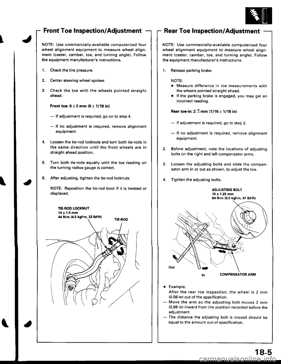
Front Toe Inspection/AdjustmentRear Toe Inspection/Adjustment
NOTE: Use commercially-available computerized four
whesl alignment equipment to measure wheel align-
ment (caster, camber, toe. and turning angle). Follow
the equipment manufacturer's instructions.
1.
2.
Check the tire pressure.
C€nter steering wheel spokes.
Check the toe with the wh€els pointed straight
ahead.
Front to6: 0 i 2 mm (0 t 1/16 in)
- lf adjustment is required. go on to step 4.
- lf no adjustment is required, remove alignment
equrpm€nr,
Loosen the ti€-rod locknuts and turn both tie-rods in
the same direction until the front wheels are in
straight ahead position.
Turn both tie-rods equally until the toe reading on
the turning radius gauge is correct.
After sdjusting, tighten the tie-rod locknuts.
NOT€: Reposition the tie-rod boot if it is twisted or
displaced.
TIE-ROD LOCKNUT14 x 1.5 mm
6.
a
NOTE: Use commercially-available computerized four
wheel alignment equipment to measure wheel align-
ment (caster, camber, toe, and turning angle), Follow
the equiDment manufacturer's instructions.
1. Release parking brake.
NOTE:
. Measure difference in toe measurements with
the wheels pointed straight ahead.
. lf the parking brake is engaged. you may get an
incorrect reading.
Rear toe-in: 2 11 mm l1l16 i 1/15 in)
- lf adjustment is required, go to step 2.
- lf no adjustment is required, remove alignment
equipment.
Before adjustment, note the locations of adjusting
bolts on the right and left compensator arms.
Loosen the adjusting bolts and slide the compen-
sator arm in or out as shown, to adjust the toe.
Tighten the adjusting bolts.
ADJUSTING BOLT10 x 1.25 mm
COMPENSATOR ARM
. Example;
A{ter the rear toe inspection, the wheel is 2 mm(0.08 inl out of the soecification.- Move the arm so the adjusting bolt moves 2 mm(0.08 inl inward from the position recorded betore theadjustment.- The distance the adjusting bolt is moved should be
equal to the amount out-of-specification.
6a N.m 16.5 kgt m, 47 lbt.ft)
a4 N.m la.s kgI.m, 33 lbf.ft)
18-5
Page 1183 of 1681
1.
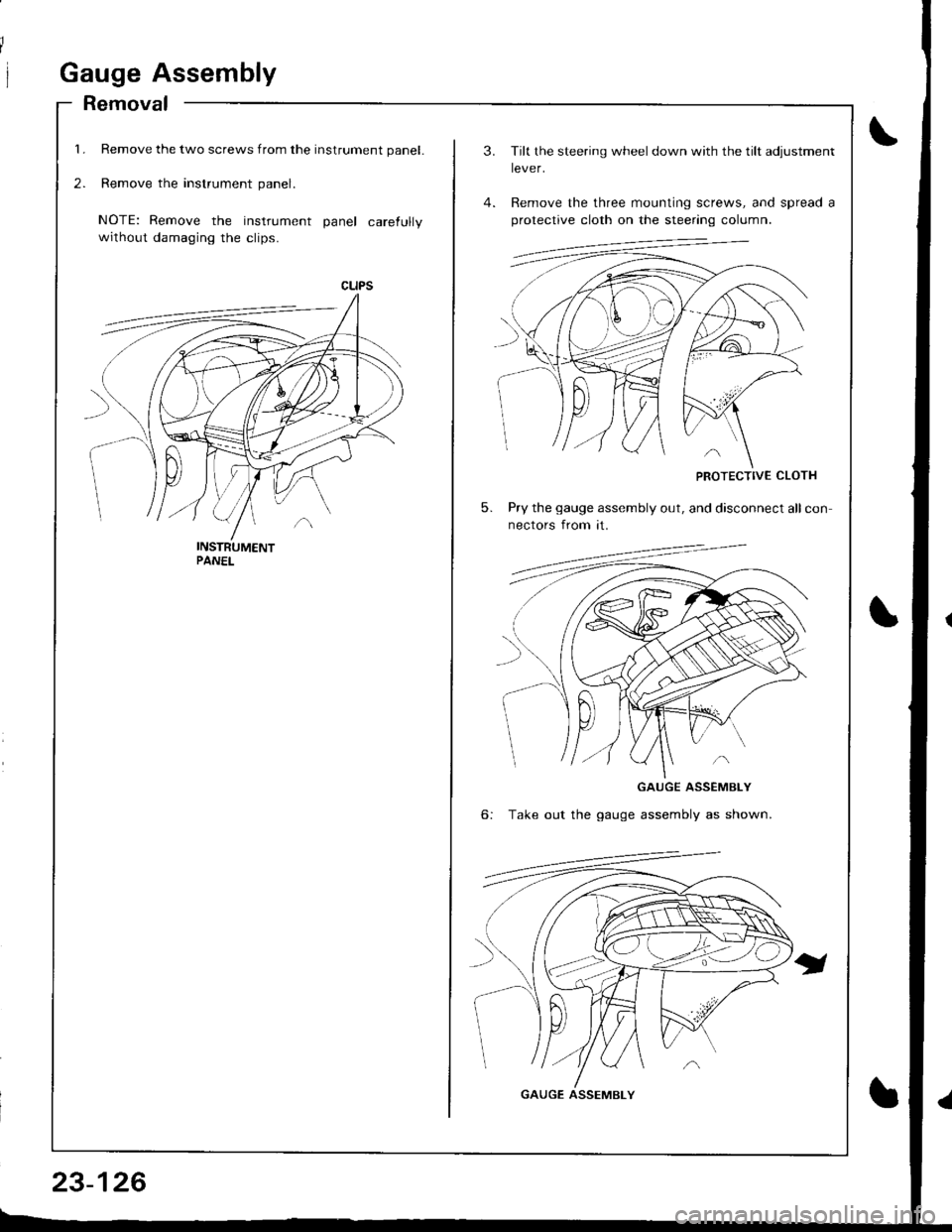
2.
Gauge Assembly
Removal
Remove the two screws from the instrument panel.
Remove the instrument panel.
NOTE: Remove the instrument panel carefully
without damaging the clips.
23-126
3.
5.
Tilt the steering wheel down with the tilt adjustment
lever.
Remove the three mounting screws, and spread a
protective cloth on the steering column.
PROTECTIVE CLOTH
Pry the gauge assembly out, and disconnect all con
nectors from it.
6:
GAUGE ASSEMBLY
Take out the gauge assembly as shown.
GAUGE ASSEMBLY