tow HONDA INTEGRA 1998 4.G User Guide
[x] Cancel search | Manufacturer: HONDA, Model Year: 1998, Model line: INTEGRA, Model: HONDA INTEGRA 1998 4.GPages: 1681, PDF Size: 54.22 MB
Page 323 of 1681
The fuel supply system co
high pressure fuel pump, t
fuel pressure regulator. f
damper, and fuel delivery i
delivers pressure-regulated
cuts the luel delivery when
Fuel Supply System
System Description
consists of a fuel tank, in-tank
r, PGM-Fl main relay, fueffilter,
. fuel injectors, fuel pulsation
y and return lines. This system
ed fuel to the fuel injectors and
rn thq engine is not running.
Fuel Pressure
Relieving
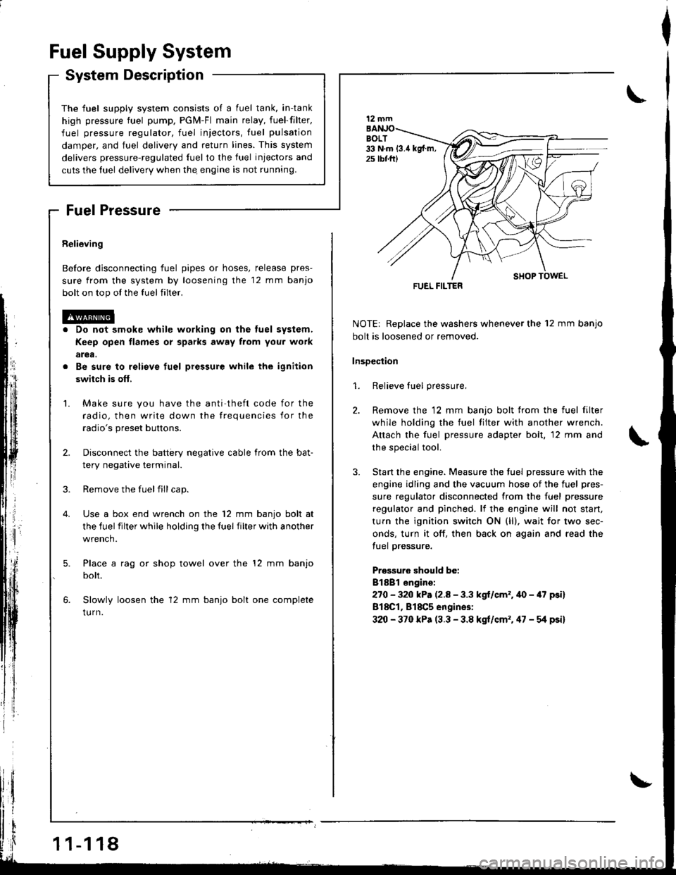
Before disconnecting fuel pipes or hoses, release pres-
sure from the system by loosening the 12 mm banjo
bolt on top ol the fuel filter.
Do not smok€ while working on the tuel system,
Keep open flames or sparks away from you. work
arga.
Be sure to relieve fuel pressure while the ignition
swiich is ofl,
Make sure you have the anti theft code for the
radio, then write down the frequencies for the
radio's preset buttons.
Disconnect the battery negative cable from the bat-
tery negative terminal.
Remove the fuelfill cap.
Use a box end wrench on the 12 mm banjo bolt at
the fuel filter while holding the fuel filter with another
wrench.
Place a rag or shop towel over the '12 mm banjo
bolt.
Slowly loosen the 12 mm banjo bolt one complete
tu rn.
1 1-1 18
I
NOTE| Replace the washers whenever the 12 mm banjo
bolt is loosened or removed.
lnsDection
1. Relieve fuel pressure.
2. Remove the 12 mm banjo bolt from the fuel filter
while holding the fuel tilter with another wrench.
Attach the fuel pressure adapter bolt, 12 mm and
the special tool.
3. Stan the engine. Measure the tuel pressure with the
engine idling and the vacuum hose of the fuel pres-
sure regulator disconnected from the fuel pressure
regulator and pinched. lf the engine will not start,
turn the ignition switch ON (ll), wait for two sec-
onds, turn it off, then back on again and read the
tuel pressure.
Pressuro should be:
Bl8Bl engire:
270 - 320 kP. (2.8 - 3.3 kgl/cm'�.40 - 47 psi)
818C1, 818C5 engines:
320 - 370 kPa (3.3 - 3.8 kgt/cm'�. 47 - g psi)
12 mm
FUEL FILTER
Page 324 of 1681
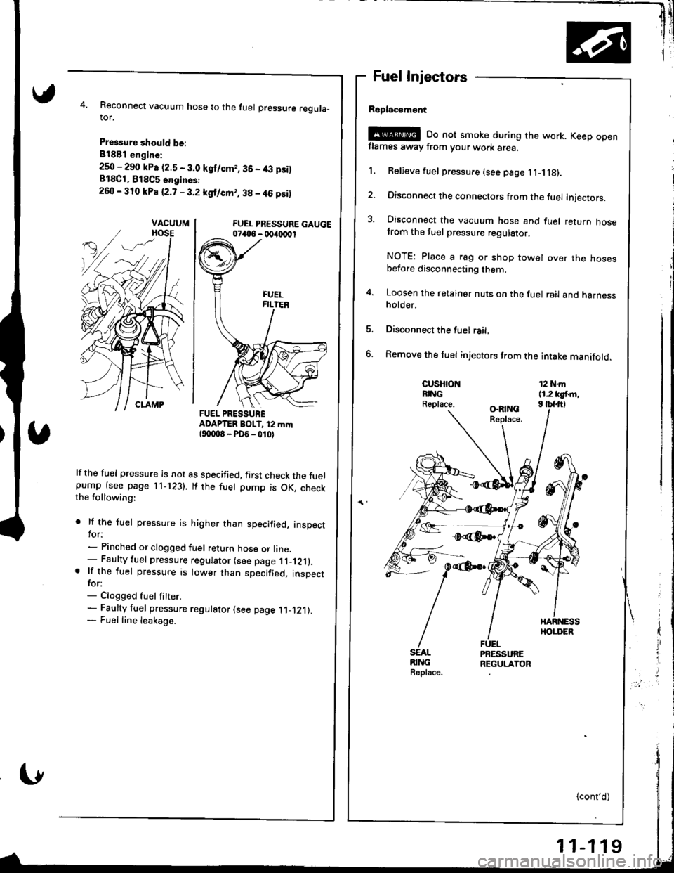
Reconnect vacuum hose to the fuel pressure reguta_ror.
Pressure should be:
818B1 engin€:
250 - 290 kPa (2.5 - 3.0 kgt/cm,, 36 - 4,:t p3i)818C1, B18C5 onginss:
260 - 310 kPa (2.7 - 3.2 kgl/cm,, 38 - 46 psi)
FUEL PRESSURE GAUGE07406 - 004{xr0r
ADAPTER BOIT, i2 mmt90008-PD6_010)
lf the fuel pressure is not as specified, first check the fuelpump (see page 11-123). tf the fuet pump is OK, checkthe following:
. lf the fuel pressure is higher than specified, inspecttor:- Pinched or clogged fuel return hose or line.- Faulty fuel pressure regulator (see page l l _121).. lf the fuel pressure is lower than specified, inspectfor:- Clogged fuel fitter.- Faulty fuel pressure regulator (see page .ll-.121).
- Fuel line leakage.
Fuel Injectors
Rsplac€msnt
!@E oo not smoke during the work. Keep openflames away from your work area.
1. Relieve fuel pressure (see page 1l- g).
2. Disconnect the connectors from the fuel injectors.
3. Disconnect the vacuum hose and fuel return hosetrom the tuel pressure regulatot.
NOTE: Place a rag or shop towel over the hosesbefore disconnecting them.
4. Loosen the retainer nuts on the fuel rail and harnessholder.
Disconnect the fuel rail,
Remove the fuel injectors from the intake manifold.
CUSHIONFINGR.place.
12 N.m11.2 kgt m,I tbfftl
SEALRINGReplace.
VACUUM
FUEL PRESSURE
Page 326 of 1681
Testing
@G Do not smoke during the test. Keep opon
flames away lrom your work ar€a.
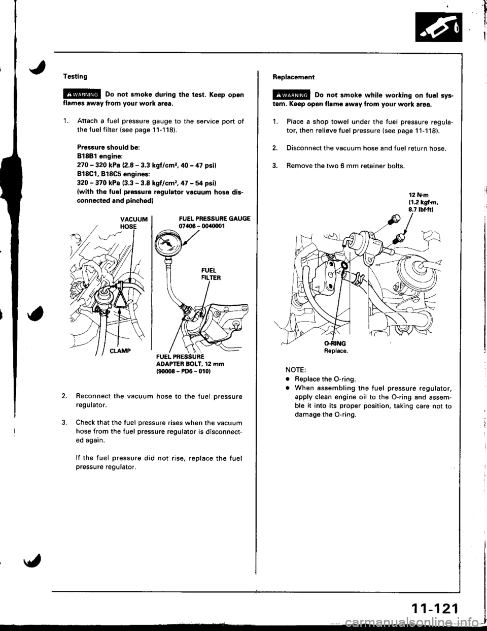
1. Attach a fuel pressure gauge to the service port of
the tuel filter (see page 11-118).
Pr€ssurs should be:
8188l €ngine:
27O - 320 kPa 12.8 - 3.3 kgl/cmr. 40 - 47 psil
818C1, 818C5 engines:
320 - 370 kPa (3.3 - 3.8 kgrf/cm,, 47 - 54 psi)
{with tho fuol pfossure regulatot vacuum hose dis-
connected and pinchsd)
FUEL PRESSURE GAUGE074t 6 - 004{1001
ADAPTER BOIT, 12 mm(9txt08-PD6-0101
Reconnect the vacuum hose to the fuel pressure
regulator.
Check that the fuel pressure rises when the vacuum
hose from the fuel pressure regulator is disconnect-
ed again.
lf the fuel pressure did not rise, replace the fuelpressure regulator.
VACUUM
FUEL PRESSURER€place.
AA
,il
I
I
Replacem6nl
@ Do not smoke while working on tucl sys-
tem. Keep open flamc away from your work area.
1. Place a shop towel under the fuel pressure regula-
tor, then relieve fuel pressure (see page 11-1'18).
2. Disconnect the vacuum hose and fuel return hose.
3. Remove the.two 6 mm retainer bolts.
NOTE:
. Replace the O-ring.
o When assembling the fuel pressure regulator,
apply clean engine oil to the O-ring and assem-
ble it into its proper position, taking care not to
damage the O-ring.
r1
i
i
11-121
Page 327 of 1681
rr*
Fuel Supply System
Fuel Filter
Replacement
Do not smoke while working on fuel system. Koop
open flame away from your work atea.
While replacing the fuel filter, be qaretul to keep a
sate distanco between battery terminals and any
tools.
The fuel filter should be replaced whenever the fuel
pressure drops below the specified value I27o - 32O kPa,
2.8 - 3.3 kgf/cm', 40 - 47 psi (B18C'1, B l8C5 enginesi 320- 370 kPa (3.3 - 3.8 kgtcm'�,47 - 54 psi) with the fuel
pressure regulator vacuum hose disconnected and
pinchedl aiter making sure that the tuel pump and the
fuel pressure regulator are OK.
Place a shop towel under and around the fuelfilter.
Relieve fuel pressure {see page 11-1'18}.
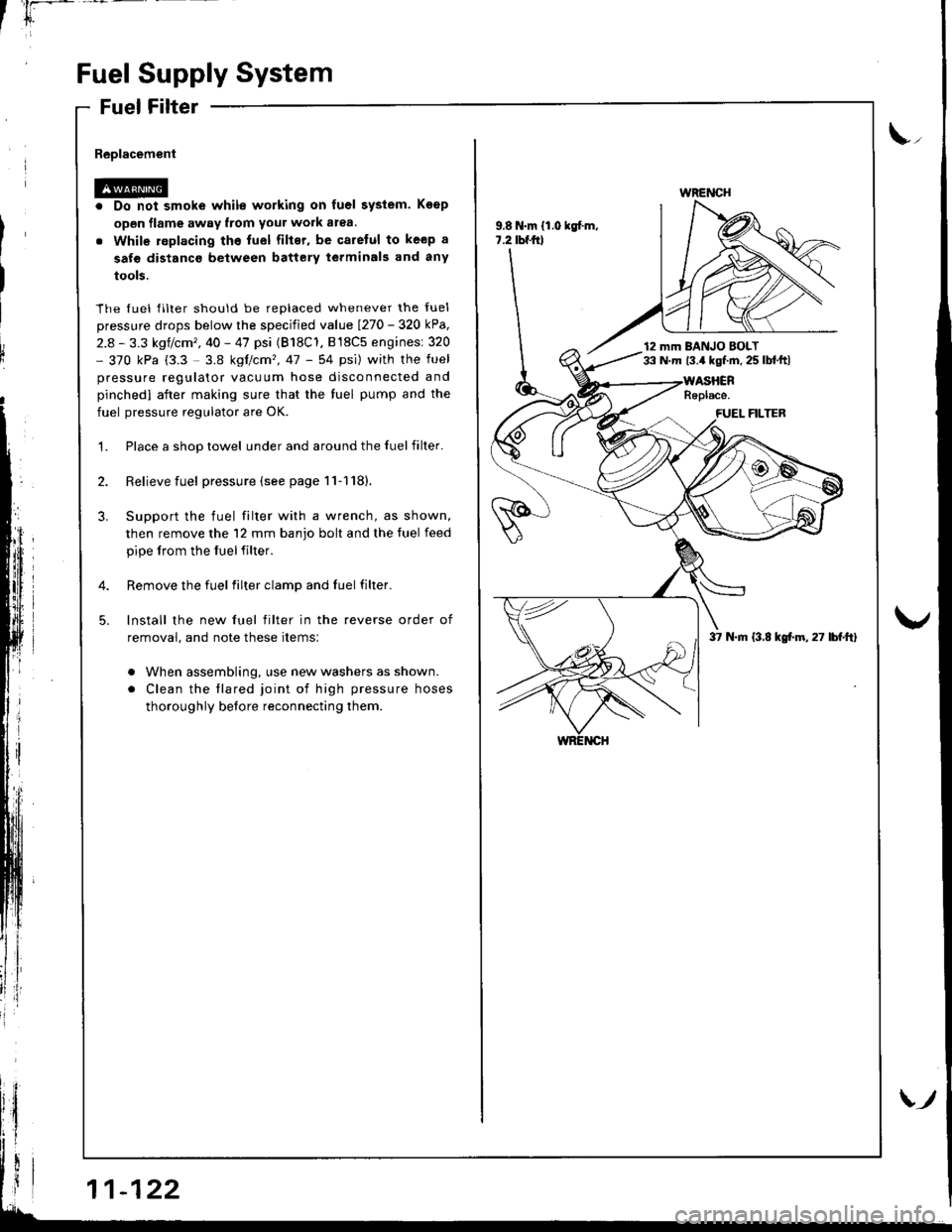
Support the fuel filter with a wrench, as shown,
then remove the 12 mm banjo bolt and the tuel feed
pipe lrom the fuelfilter.
Remove the fuel filter clamp and fuel filter.
lnstall the new fuel filter in the reverse order of
removal, and note these items:
. When assembling, use new washers as shown.
. Clean the tlared joint of high pressure hoses
thoroughly before reconnecting them.
\,,
9.8 N.m {1.0 kgf.m,7.2 tbf.frl
WRENCH
12 mm BANJO BOLT33 N.m 13.4 kgf.m. 25 lbl.ftl
37 N.m (3.8 kgf.m,27 lbf.ft)
Page 362 of 1681
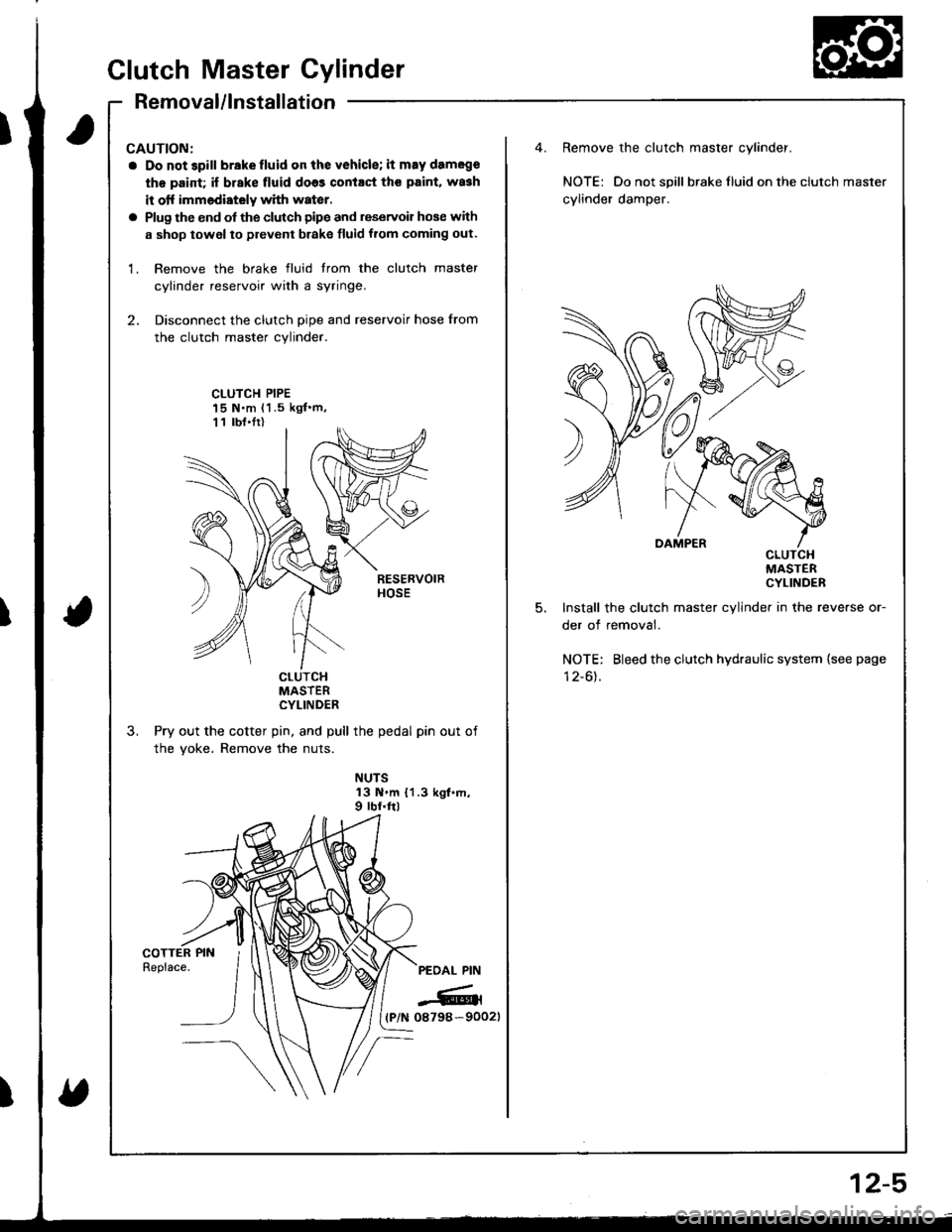
CAUTION:
a Do not 3pill brakefluid on the vehicle; it may damege
th€ paid; if brake fluid do63 contact th€ paint. wa3h
it otf immediately with water.
a Plug the end of the clutch pipe and reservoir hose with
a shop towel to prevent brake fluid from coming out.
1. Remove the brake fluid trom the clutch master
cylinder reservoir with a syringe,
2. Disconnect the clutch pipe and reservoir hose from
the clutch master cylinder.
Remove the clutch master cylinder.
NOTE: Do not spill braketluid ontheclutch master
cylinder damper.
CLUTCH PIPE15 N.m {1 .5 kgf'm,11 lbt.Ir)
5.
cLulcHMASTERCYLINDER
Install the clutch master cylinder in the reverse or-
der of removal.
NOTE: Bleed the clutch hydraulic system {see page
I z-ol.cturcHMASTERCYLINDER
Pry out the cotter pin, and pull the pedal pin out of
the yoke. Remove the nuts.
NUTS13 N.m {1.3 kgt.m,9 rbf.ftl
PEOAL PIN
-6rl(P/N 08798-90021
Clutch Master Cylinder
Removal/lnstallation
2-5
Page 363 of 1681
T
fi
;ill
Slave Cylinder
Removal/lnstallation
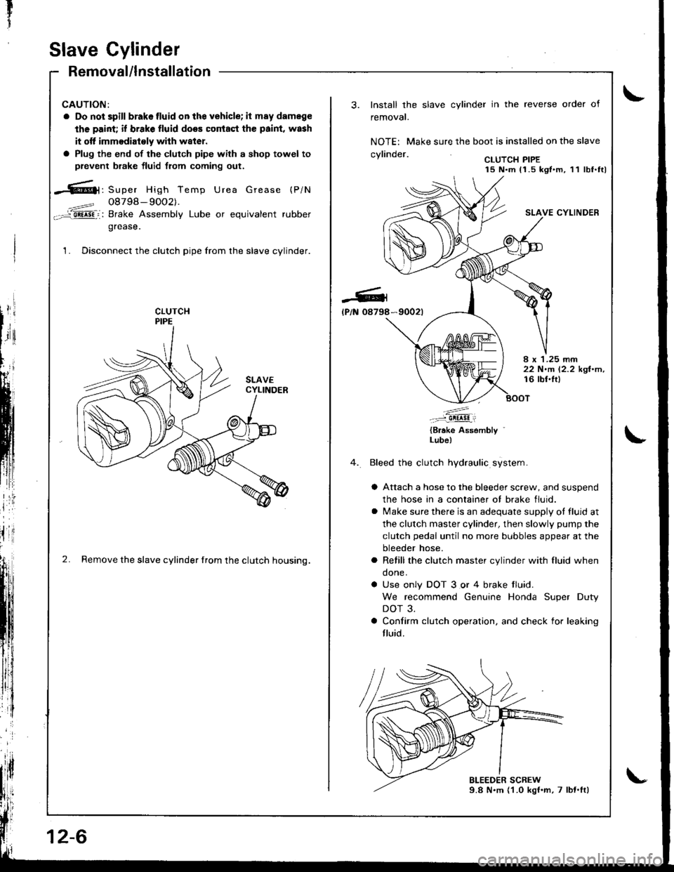
CAUTION:
a Do not spill brakelluid onthe vehicle; it may dameg€
the paint; if brake fluid does coniaqt the paint, wash
it otf immodiaioly wilh w8ter.
a Plug the end of the clutch pipe with a shop towel to
prevent brake fluid from coming out.
-6|1, Super High Temp Urea Grease (P/N
4==? 08798- 9OO2).-='aii^5Fi: Brake Assembly Lube or equivalent rubber
grease.
1. Disconnect the clutch pipe from the slave cylinder.
2. Remove the slave cylinder from the clutch housing.
12-6
-Gl
lP/N 08798
Install the slave cylinder in the reverse order of
removal.
NOTE: Make sure the boot is installed on the slave
.wlin.larCLUTCH PIPE15 N.m 11.5 kgt.m, 11 lbf.ttl
SLAVE CYLINDER
*9002t
I x 1.25 rnm22 N.m 12.2 kgl.m,16 lbl.lt)
.'....-..-:::-9!!!!!i
{Brake Assembly '
Lube)
Bleed the clutch hydraulic system.
a Attach a hose to the bleeder screw, and suspend
the hose in a container ot brake fluid.
a lvlake sure there is an adequate supply ot fluid at
the clutch master cylinder, then slowly pump the
clutch pedal until no more bubbles appear at the
bleeder hose.
a Refill the clutch master cylinder with fluid when
done.
a Use only DOT 3 or 4 brake tluid.
We recommend Genuine Honda Super Duty
DOT 3.
a Confirm clutch operation. and check for leaking
fluid.
Page 406 of 1681
Mainshaft Thrust Clearance
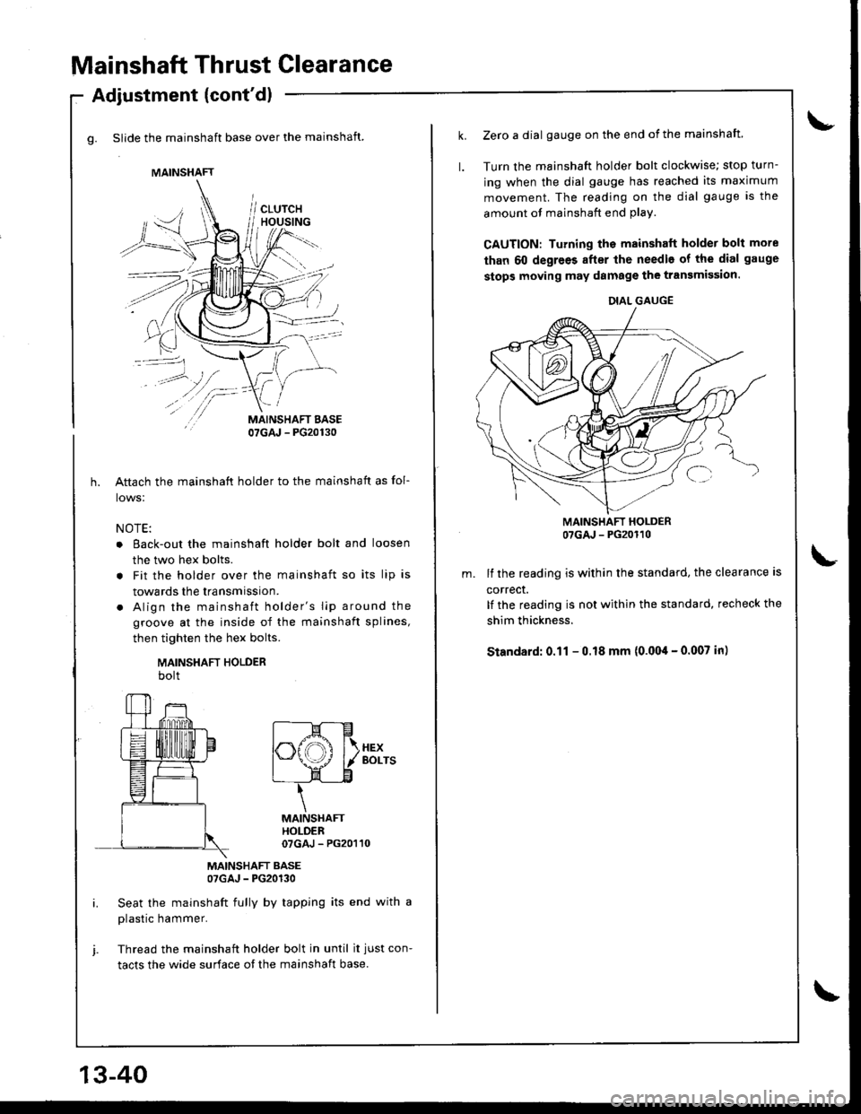
g. Slide the mainshaft base over the mainshaft.
Adjustment (cont'dl
/\
/-
MAINSHAFT BASE07GAJ - PG20130
Aftach the mainshaft holder to the mainshaft as fol-
lows:
NOTE:
o Eack-out the mainshaft holder bolt and loosen
the two hex bolts.
. Fit the holder over the mainshaft so its lip is
towards the transmission.
. Align the mainshaft holder's lip around the
groove at the inside of the mainshaft splines,
then tighten the hex bolts.
MAINSHAFT HOLDERbolt
MAINSHAFT BASE07GAJ - PG20130
Seat the mainshaft fully by tapping its end with a
plastic hammer.
Thread the mainshaft holder bolt in until it just con-
tacts the wide surface of the mainshaft base.
MAINSHAFT
f----M---E
|".ffi f\.xex
I \J \--l./ l/ Borrs
L- LE
\
MAINSHAfiHOLDER07GAJ - PG20110
13-40
Zerc a dial gauge on the end of the mainshaft.
Turn the mainshaft holder bolt clockwise; stop turn-
ing when the dial gauge has reached its maximum
movement. The reading on the dial gauge is the
amount of mainshaft end plav.
CAUTION: Turning the mainshaft holder bolt more
than 60 degrees after the needle of the dial gauge
stops moving may damage the transmission.
MAINSHAFT HOLDER07GAJ - PG20110
lf the reading is within the standard, the clearance is
correct.
It the reading is not within the standard, recheck the
shim thickness.
Standard: 0.11 - 0.18 mm (0.004 - 0.007 in)
DIAL GAUGE
Page 450 of 1681
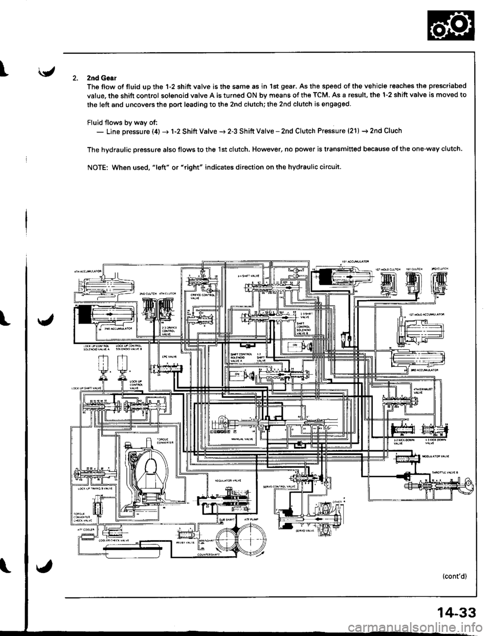
Iznd Goar
The ftow ot fluid up the 1-2 shift valve is the same 8s in 1st gear. As the speed of the vehicle reaches the prescriabed
value, the shift control solenoid valve A is turned ON by means of the TCM. As a result, the 1-2 shift valve is moved to
the left and uncovers the port leading to the 2nd clutch; the 2nd clutch is engaged.
Fluid flows by way of:- Line pressure (4) -r 1-2 Shift Valve i 2-3 Shift Valve - znd Clutch Pressure (21) i 2nd Cluch
The hydraulic pressure also flows to the lst clutch. However, no pow€r is transmitted because ofthe one-way clutch.
NOTE: When used, "Ieft" or "right" indicates ditection on the hydraulic circuit.
14-33
Page 537 of 1681
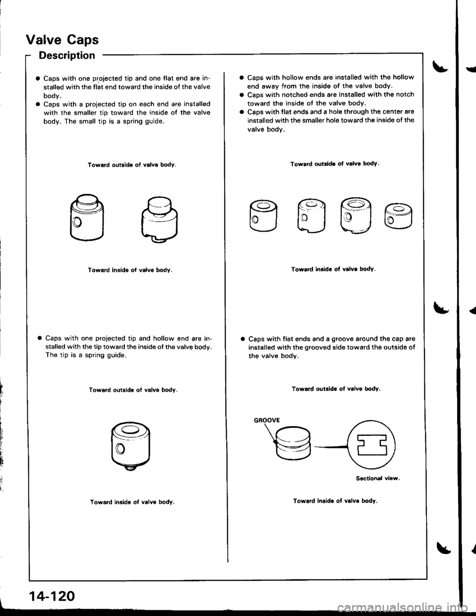
Valve Caps
Description
a Caps with one projected tip and one flat end are in-
stalled with the flat end toward the inside oJ the valve
body.
a Caps with a proiected tip on each end are installed
with the smaller tip toward the inside of the valve
body. The small tip is a spring guide.
Toward outsid6 ot v6lvo body.
Toward insido of valvo bodv.
Caps with one projected tip and hollow end are in-
stalled with the tip toward the inside of the valve body.
The tip is a spring guide.
Tow6.d outsid€ ot valvo bodY.
Tow6rd in3id6 ol valvo bodv.
, 14-120
CaDs with hollow ends are installed with the hollow
end away from the inside of the valve body.
Caps with notched ends are installed with the notch
toward the inside ot the valve body.
Caps with tlat ends and a hole through the center are
installed with the smaller hole toward the inside of the
valve body.
Toward ouGida ol valvo body.
Efla
Toward in.ldo ot valve bodY.
Caps with tlat ends and a groove around the cap are
installed with the grooved side toward the outside of
the valve bodv.
Toward oulrlda of valve bodv.
"-\"h
,a\
v{9
Sociiohal viow.
Toward insido ot v.lvo body.
I
{
Page 566 of 1681
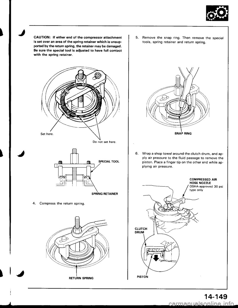
I
T
)
CAUTION: lf either end of the comoressor attachment
is set over an area of the spring letainsr which is unsup-
portod by the retum spring, the retainer may be damaged.
Be sur6 the special tool is adiusted to have full contact
with the spring ietainel,
RETAINER
4. Compress the return spring.
Do not set here.
RETURN SPRING
)
14-149
5.Remove the snap ring. Then remove the specialtools, spring retainer and return spring.
Wrap a shop towelaround the clutch drum, and ap-ply air pressure to the fluid passage to remove thepiston. Place a finger tip on the other end while ap,plying air pressure.
COMPRESSED AIRHOSE NOZZLEOSHA-approved 30 psi
CLUTCH
SNAP RING
PISTON