tow HONDA INTEGRA 1998 4.G Workshop Manual
[x] Cancel search | Manufacturer: HONDA, Model Year: 1998, Model line: INTEGRA, Model: HONDA INTEGRA 1998 4.GPages: 1681, PDF Size: 54.22 MB
Page 67 of 1681
Valve Seals
Replacement (cylinder head removal not required)
The procedure shown below applies when using the in-
car valve spring compressor (Snap-on YA8845 with
Y AAA45-2A 1 /8" attachment).
!@@ When using this tool, as with any tool,
always use approved eye protection. Using the
fight tool tor each job helps increase productivity
while safeguarding tools, equipment and ihe user.
Turn the crankshaft so that the No. 1 and the No. 4pistons are at top dead center (TDC).
Remove the cylinder head cover.
Remove the distributor.
Loosen and disconnect the timinq belt from the
camshaft oullevs.
5. Remove the camshaft holder bolts, then remove the
camshaft holders, the camshafts and rocker arms.
Intake Valve Seals
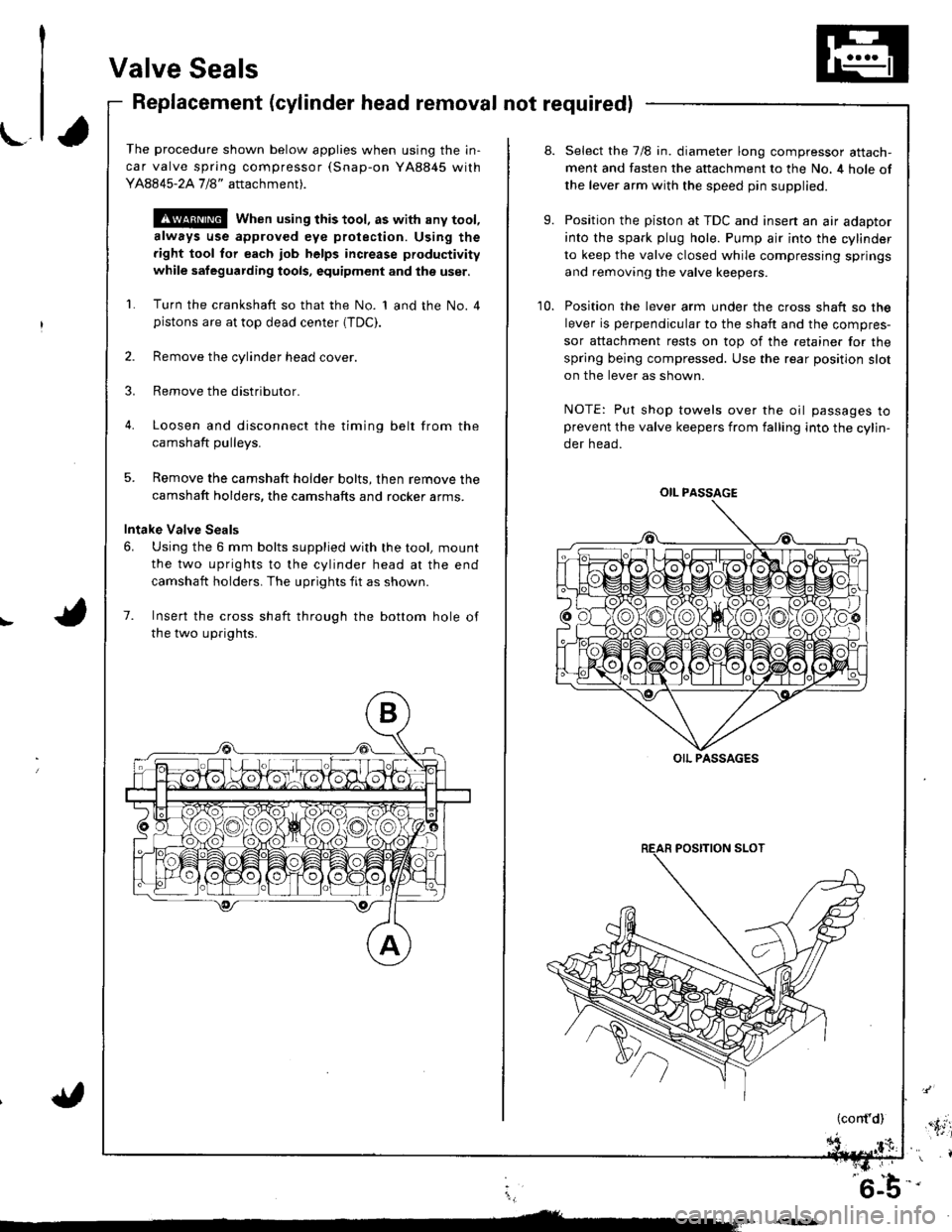
6. Using the 6 mm bolts supplied with the tool, mount
the two uprights to the cylinder head at the end
camshaft holders. The uprights fit as shown.
7. Insert the cross shaft through the bottom hole of
the two uprights.
8.
9.
10.
Select the 7/8 in. diameter long compressor attach-
ment and fasten the attachment to the No. 4 hole of
the lever arm with the speed pin supplied.
Position the piston at TDC and insen an air adaptor
into the spark plug hole. Pump air into the cylinder
to keep the valve closed while compressing springs
and removing the valve keepers.
Position the lever arm under the cross shaft so the
lever is perpendicular to the shaft and the compres-
sor attachment rests on top of the retainer for the
spring being compressed. Use the rear position slot
on the lever as shown.
NOTE: Put shop towels over the oil passages toprevent the valve keepers from falling into the cylin-
der head.
OIL PASSAGE
OIL PASSAGES
(cont'd),'.itil
i,
'6-b-'
Page 87 of 1681
\-
Installation Sequence
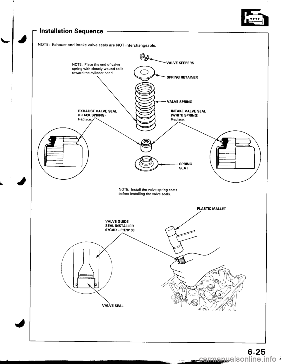
Exhaust and intake valve seals are NOT interchanoeable.
NOTE: Place the end of valvespring with closely wound coilstoward the cylinder head.
EXHAUST VALVE SEALIBLACK SPRING}Replace.
@A..'..--uoruEKEEPER'
9-...-'PRTNGREYATNER
VALVE SPRING
INTAKE VALVE SEALIWHITE SPRINGIReplace.
I
PLASTIC MALLET
VALVE GUIDESEAL INSTALLER07GAD - PH70100
,@.t.'( (Sz) I<-- SPRING
V SEAT
NOTE: lnstall the valve spring seatsbefore installing the valve seals.
6-25
Page 89 of 1681
\,
Replacement
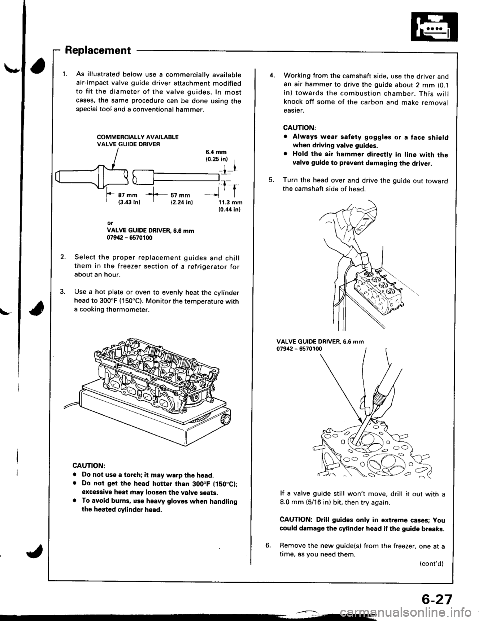
1. As illustrated below use a commercially available
air-impact valve guide driver attachment modified
to fit the diameter of the valve guides, In most
cases, the same procedure can be done using thespecial tool and a conventional hammer.
6.il mm{0.25 inl
rr
*f-::rtl1-r87 mm{3.43 in)11.3 mm10.44 inl
orVALVE GUIDE DBIVER, 6.6 mm07942 - 6570100
Select the proper replacement guides and chillthem in the freezer section of a refrigerator forabout an hour.
Use a hot plate or oven to evenly heat the cylinderhead to 300"F (150"C). Monitor the temperature witha cooking thermometer.
CAUTION:
. Do not use a torch; it may warp the hoad.. Do not ger tho head hotter than 300.F ltS0"C);exces3ive heat may loo3en the valvo seats.. To avoid burns, uss heaw gloves when handlingthe heat€d cylinder head.
12.21inl
6-27
Working trom the camshaft side, use the driver and8n air hammer to drive the guide about 2 mm (0.1
in) towards the combustion chamber. This willknock off some of the carbon and make removaleaster.
CAUTION:
. Always wear safety goggles or a face shieldwhen driving valve guides.
. Hold the air hammer direcfly in line with thevalve guide to prevent damaging the driver.
Turn the head over and drive the guide out towardthe camshaft side of head.
5.
VALVE GUIDE DRIVER.079i12 - 65701006.6 mm
lf a valve guide still won't move. drill it out with a
8.0 mm (5/16 in) bit, then try again.
CAUTION: Drill guides only in extreme cases; You
could damage the cylinder head it the guide breaks.
6. Remove the new guide{s) from the freezer, one at atime, as you need them.
{cont'd)
OO
'o c,
Page 94 of 1681
Cylinder Head
Installation (cont'dl
9, Tighten the camshaft holders temporarily.
a Make sure that the rocker arms are properly
positioned on the valve stems
10. Tighten each bolt in two steps to ensure that the
rockers do not bind on the valves.
NOTE: wipe off the excess of liquid gasket from
No. 1 and No. 6 camshaft holder with a shop towel
6x1.0mm9,8 N.m 11.0 kgf m, 7.2 lbt'ftl
\-
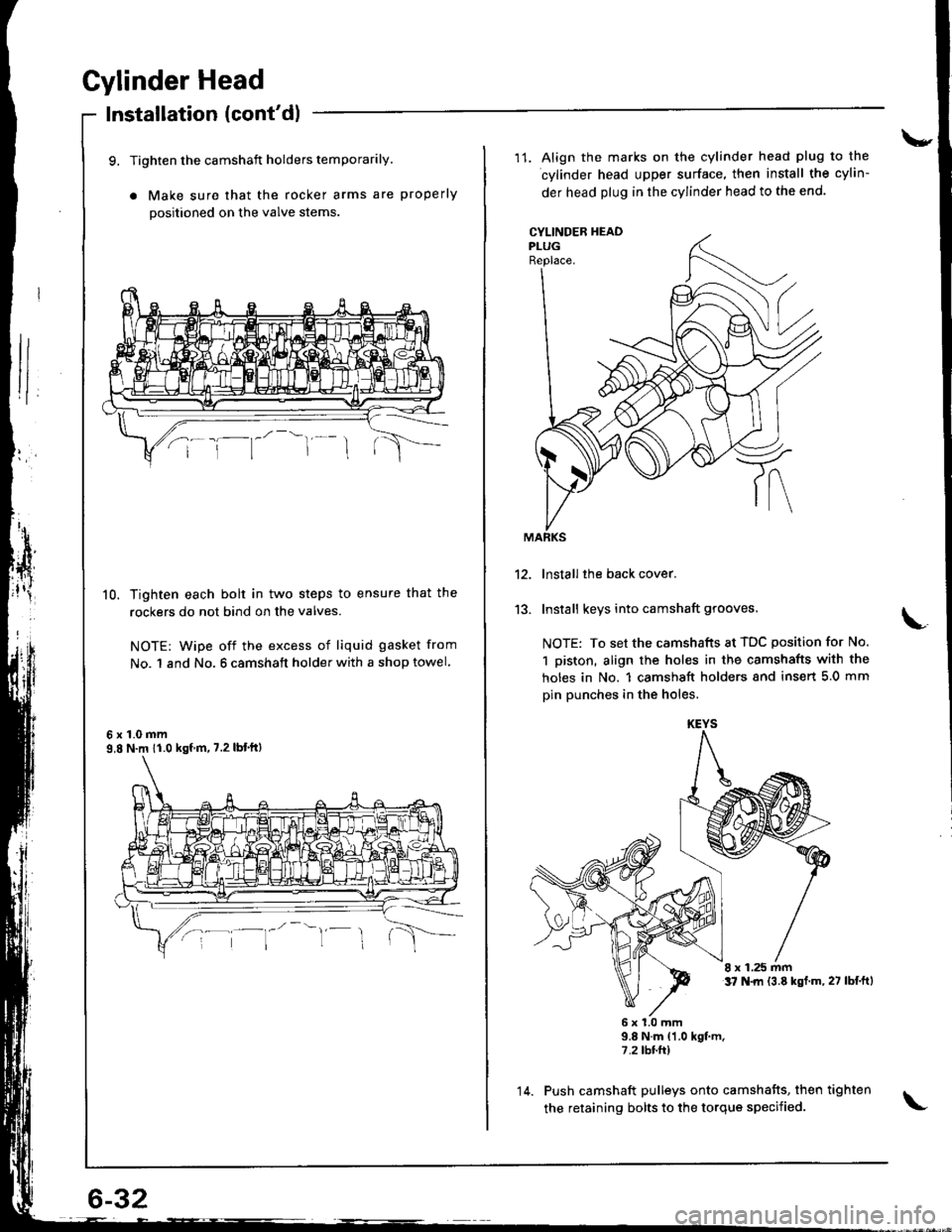
11. Align the marks on the cylinder head plug to the
cylinder head upper surface, then install the cylin-
der head plug in the cylinder head to the end.
CYLINDEB HEADPLUGReplace.
13.
lnstall the back cover.
Install keys into camshaft grooves.
NOTE: To set the camshafts at TDC position for No.
1 piston, align the holes in the camshafts with the
holes in No. 1 camshsft holders snd insert 5.0 mm
pin punches in the holes.
8 x 1.25 mmt7 N.|rl {3.8 kst.m,27 lbf.ftl
6x1.0mm9.8 N.m {1.0 kgt m.7.2 tbr.ft)
Push camshaft pulleys onto camshafts, then tighten
the retaining bolts to the torque specified.
KEYS
14.
Page 96 of 1681
Cylinder Head
Installation (cont'dl
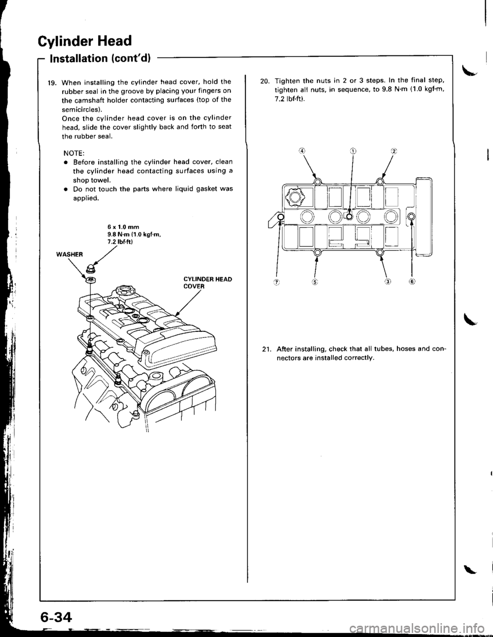
19. When installing the cylinder head cover. hold the
rubber seal in the groove by placing your fingers on
the camshaft holder contacting surfaces (top of the
semicircles).
Once the cylinder head cover is on the cylinder
head, slide the cover slightly back and iorth to seat
the rubber seal.
NOTE:
. Before installing the cylinder head cover, clean
the cylinder head contacting surfaces using a
shop towel.
. Do not touch the parts where liquid gasket was
applied.
6x1.0mm9.8 N.m {1.0 kgf.m,7 .2 tblltl
6-34
\
21.
Tighten the nuts in 2 or 3 steps. In the final step,
tighten ali nuts, in sequence, to 9.8 N'm (1.0 kgim,
7.2 tbf.ft).
After installing, check that all tubes, hoses and con-
nectors are installed correctly.
Page 152 of 1681
/
li
l
Main Bearings
Clearance
2.
3.
1.
4.
To check main bearing-to-iournal oil clearance,
remove the main caps and bearing halves.
Clean each main iournal and bearing half with a
clean shop towel.
Place one strip of plastigage across each main iour-
na l-
NOTE: lf the engine is still in the car when you bolt
the main cap down to check clearance, the weight
of the crankshaft and flywheel will flatten the plasti'
gage further than just the torque on the cap bolt,
and give you an incorrect reading. For an accurate
reading, support the crank with a jack under the
counterweights and check only one bearing at a
trme.
Reinstall the bearing caps and cap bridge (B18C1,
B18C5 engines only)then torque the bolts.
Bl8Bl engine: 77 N'm (7.8 kgt.m.56lbf.ft)
B18Cl,818C5 engines:
No. 1,5 cap bolts 73 N.m (7.4 kgf.m,56lbnftl
No. 2. 3, 4 cap bolts 64 N.m {6.5 kgf m. 49 lbf ftl
NOTE: Do not rotate the crankshaft during inspec-
tro n.
Remove the cap bridge (818C1, 818C5 engines
only), caps and bearings again, and measure the
widest part of the plastigage.
Main Bearing-to-Journal Oil Clearance:
Standard lNew):
No. 1, 2, 4, 5: 0.024 - 0.042 mm
10.0009 -0.0017 in)
Service Limit:0.050 mm (0.0020 in)
No.3:0.030 - 0.048 mm
10.0012 - 0.0019 inl
Service Limit:0.060 mm {0.0024 inl
PLASTIGAGE STRIP
lf the plastigage measures too wide or too narrow,
{remove the engine if it's still in the car), remove the
crankshaft, and remove the upper half of the bear-
ing. lnstall a new, complete bearing with the same
color code (select the color as shown in the right
column), and recheck the clearance.
CAUTION: Do not file, shim. or scrape the bearings
or the caps to adiust clearance.
lf the plastigage shows the clearance is still incor-
rect, try the next larger or smaller bearing (the color
listed above or below that one), and check again.
NOTE: lf the oroDer clearance cannot be obtained
by using the appropriate larger or smaller bearings.
reolace the crankshaft and start over.
Selection
CAUTION: lf the codes ale indecipherable because of
an accumulation oI dirt and dust, do not scrub them
with a wire bru6h or scraper. Clean lhem only with sol-
vent or detergent.
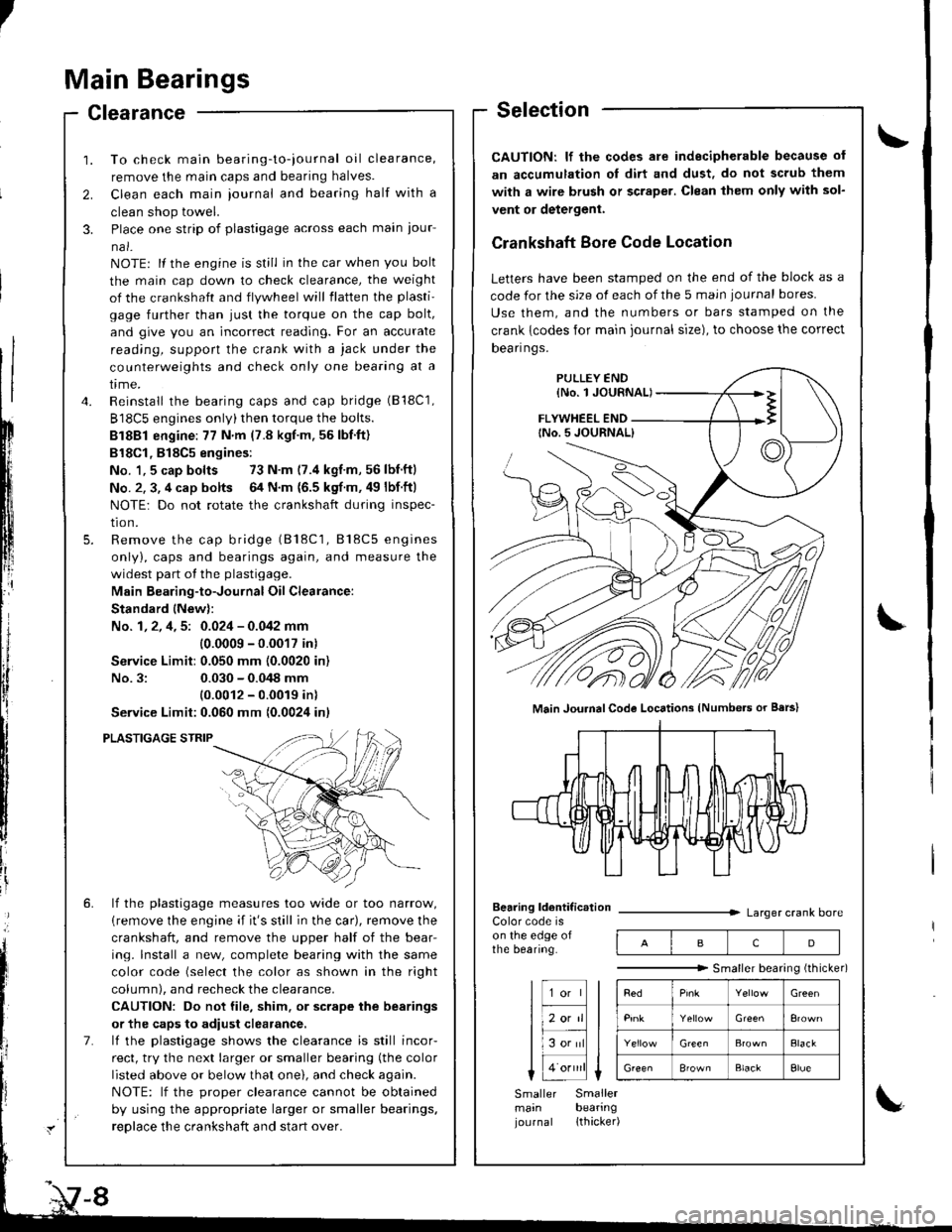
Crankshaft Bore Code Location
Letters have been stamped on the end of the block as a
code for the size of each of the 5 main iournal bores
Use them, and the numbers or bars stamped on the
crank {codes for main journal size), to choose the correct
Dean nqs,
FLYWHEEL END
Main JouhalCode Locations (Numbe.s or Bars)
Bearing ldentif ic.tionColor code ison the edge ofthe bearing.
Larger crank bore
acD
"""""""" Smallerbearingithicker)
Green
Elack
B'ownBlackElue
Smaller Smallermain bearingjournal lthacker)
Page 153 of 1681
I
IConnecting Rod Bearings
Clearance
1. Remove the connecting rod cap and bearing half.2. Clean the crankshaft rod journal and bearing halfwith a clean shop towel.
3. Place the plastigage across the rod journal.
4. Reinstall the bearing half and cap, and torque thenuts (818C5 engine: see page 7-19).
81881 engine:31 N.m (3.2 kgnm,23 tbf.ftl
Bl8Cl engine:44 N.m (4.5 kgl.m.33 tbl.ft)
NOTE: Do not rotate the crankshaft during inspection.
Connecting Rod Bearing-to-Journal Oil Clearance:81881 engine:
Standard {Newl: 0.020 - 0.038 mm
{0.0008 - 0.0015 inl
Service Limit: 0.050 mm {0.0020 inl
818C1 engine:
Standald {Newl: 0.032 - 0.050 mm
10.0013 - 0.0020 in)
Service Limit: 0.060 mm {0.0024 in}
B18C5 engine:
Standard lNew): 0.038 - 0.050 mm(0.0015 - 0.0020 inl
Service Limit: 0.060 mm t0.0024 inl
lf the plastigage measures too wjde or too narrow,remove the upper half of the bearjng, install a new,complete bearing with the same color code (select
the color as shown in the rig ht column), andrecheck the clearance.
CAUTION: Do not file, shim, or scrape the bearingor the caps to adiust clearance.
It the plastigage shows the clearance is still incorrect,try the next larger or smaller bearing (the color listedabove or below that one), and check clearance again.
NOTEr It the proper clearance cannot be obtainedby using the appropriate larger or smaller bearings,replace the crankshaft and stan over.
Selection
CAUTION: lf the codes are indecipherable because ofan accumulation of dirt and dust, do not scrub themwith a wire brush or scraper. Clean them only with sol-vent or delergent.
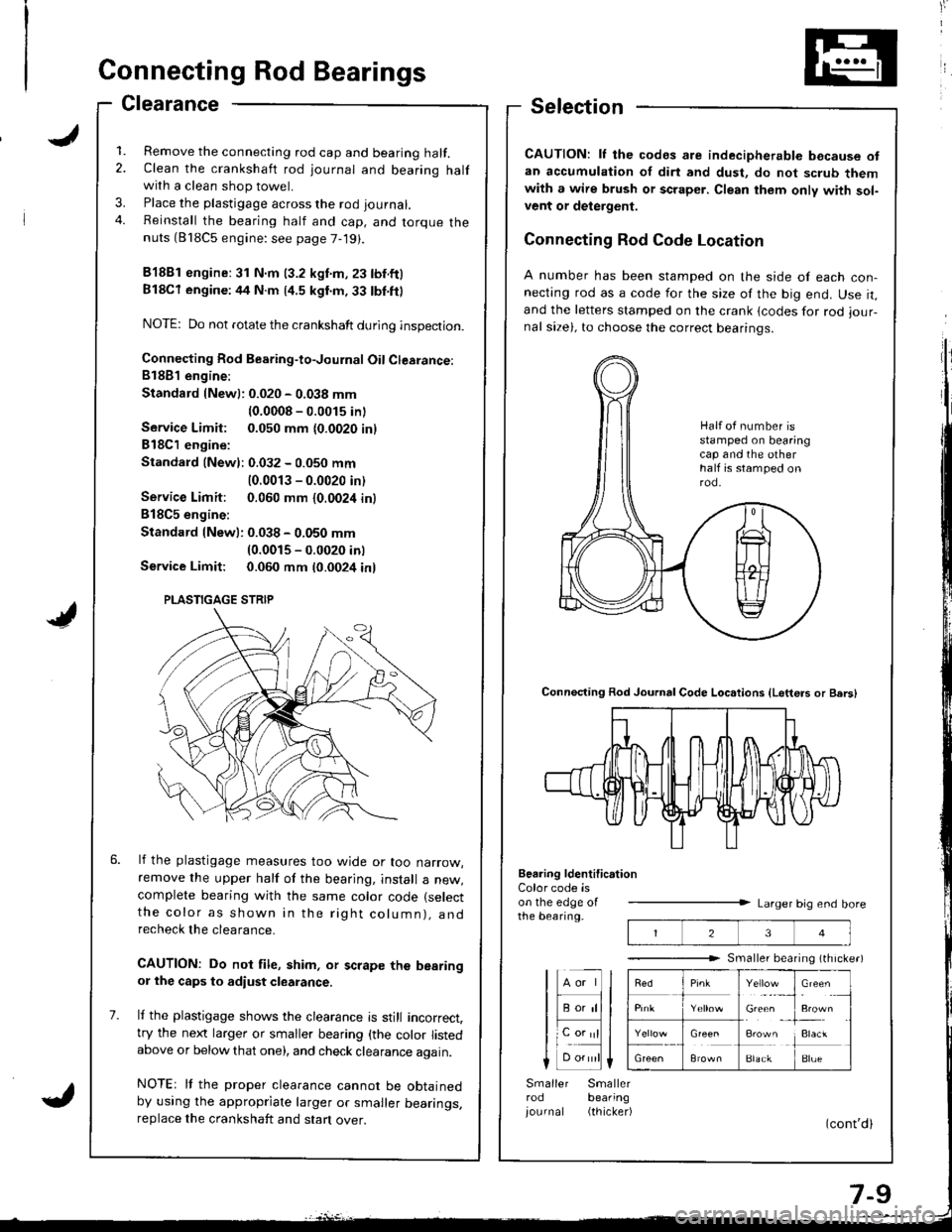
Connecting Rod Code Location
A number has been stamped on the side of each con-necting rod as a code for the size of the big end. Use it,and the letters stamped on the crank lcodes for rod iour-nal size), to choose the correct bearinqs.
Connecting Rod Journal Code Loc.tions {Letters or Bers)
Beering ldentification
23
Y"rl.:_,
Gie& ,
!**
i:1"
BlackBlue
Color code ison the edge oIthe bearing.Larger big end bore
Smaller bearing (th rche.)
lHll
I F;;lll
lL".;|l
Smaller Smallerrod bearing
iournal (thicker)
Half ot number isstamped on bearingcap and the otherhalf is stamped onrod.
PLASTIGAGE STRIP
Page 156 of 1681
Grankshaft
Removal (cont'dl
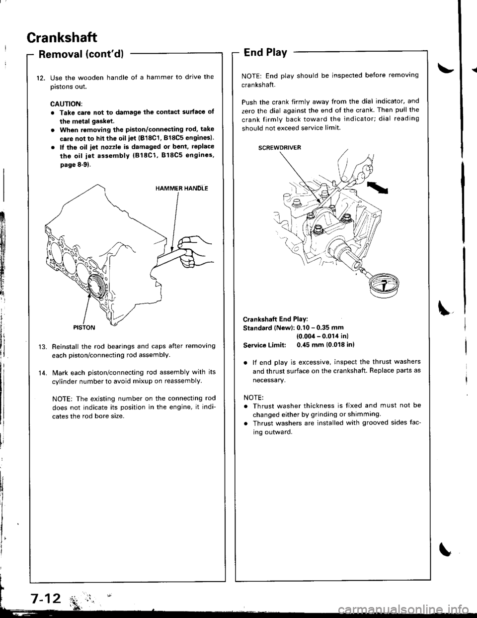
Use the wooden handle ot a hammer to drive the
pistons out.
CAUTION:
. Take care not to damage the contact surface ot
the metal gasket.
. When removing the piston/connecting rod, take
care not to hit the oil iet (818C1, 818C5 enginesl.
. ll the oil iet nozzle is damaged or bent, replace
the oil iet assembly {818C1, B18C5 engincs.
page 8-9).
Reinstall the rod bearings and caps after removing
each piston/connecting rod assembly.
l\4ark each piston/connecting rod assembly with its
cylinder number to avoid mixup on reassembly.
NOTE; The existing number on the connecting rod
does not indicate its position in the engine, it indi-
cates the rod bore size.
End Play
NOTE: End play should be inspected before removing
crankshaft.
Push the crank firmly away from the dial indicator, and
zero the dial against the end of the crank. Then pull the
crank firmly back toward the indicator; dial reading
should not exceed service limit.
Crankshaft End Play:
Standard (New): 0.10 - 0.35 mm
{0.00'l - 0.014 inl
Service Limit: 0.45 mm 10.018 inl
. lf end play is excessive, inspect the thrust washers
and thrust surface on the crankshaft. Replace parts as
necessary.
NOTE:
. Thrust washer thickness is tixed and must not be
changed either by grinding or shimming.
. Thrust washers are installed with grooved sides fac-
ing outward.
12.
14.
Frlfll
ftl
t
iffi[l
t,,tlr
lt
i
Page 244 of 1681
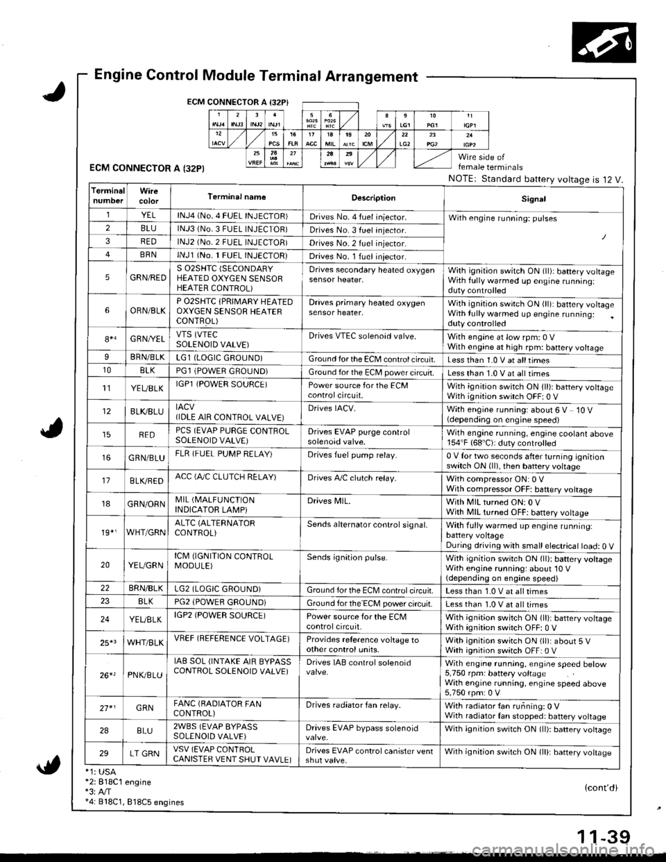
Engine Control Module Terminal Arrangement
ECM CONNECTOR A I32P}
ECM CONNECTOR A I32PI
*1: USA*2:818C1 engine*3:A,/T*4: 818C1, 818C5 engines
female terminals
NOTEr Standard battery voltageis 12 V.
{cont'di
LG22A
TerminalWireTerminal nameDescriptionSignal
YELlNJ4 (No. 4 FUEL INJECTOR)Drives No. 4 fuel iniector.With engine running: pulses2BLUlNJ3 (No.3 FUEL INJECTOR)Drives No. 3 fuel injector.
3REDlNJ2 (No.2 FUEL INJECTOB)Drives No.2 fuel injector.
BRNlNJl (No. 1 FUEL INJECTOR)Drives No. l Iuel iniector.
5GRN/REDS 02SHTC (SECONDARY
HEATED OXYGEN SENSORHEATER CONTROL)
Drives secondary heated oxygensensor heater,With ignition switch ON (ll)i battery volrageWith fully warmed up engine runningiduty controlled
6ORN/BLKP O2SHTC {PRIMARY HEAIEDOXYGEN SENSOB HEAIERCONTFOL)
Draves primary heated oxygensensor heater,With ignition swirch ON (ll): battery voltageWith lully warmed up engine running:duty controlled
84G RNI/ELVTS (VTEC
SOLENOID VALVE)Drives VTEC solenoid valve.With engine at low rpm: 0 VWith engine at high rpm: battery voltageIBRN/BLKLG1 (LOGIC GROUND)Ground for the ECM control circuit.Less than 1.0 V at alltimes10BLKPGl (POWER GROUND)Ground for the EC[, power circuit.Less than 1.0 V at all times't'lYEUBLKIGPl {POWER SOURCE)Power source for the ECMcontrolcircuit.With ignition switch ON 1ll): battery voltageWith ignition switch OFF| 0 V
12BLI(8LUIACV(IDLE AIR CONTROL VALVE}Drives IACV.With engine running: about 6 V 10 V(depending on engine speed)
REDPCS (EVAP PURGE CONTROLSOLENOID VALVE)Drives EVAP purge controlsolenoid valve.Wilh engane running, engine coolant above154"F (68'C): duty controlled
GRN/BLUFLR (FUEL PUMP RELAY)Drives fuel pump relay.0 V for two seconds after turning ignitionswitch ON (ll), then battery voltage
17B LVBEDACC (fuC CLUTCH RELAY)Drives A,/C clulch relay.With compressor ON: 0 VWith compressor OFFt baftery voltage
18GRN/ORNMIL (I\4ALFUNCTION
INDICATOR LAMPiDrives MlL.With MIL turned ON:0 VWjth MIL turned OFF: battery vottage
19*,WHT/GRNALTC (ALTERNATOR
CONTROL)Sends alternator control signal,With fully warmed up engine runninglbattery voltageDuring driving with small electrical load: 0 V
20YEUGRNICM (IGNITION CONTROLMODULE)Sends ignition pulse.With ignition switch ON (ll): battery voltageWith engine running: about'10 V(depending on engine speed)22BRN/BLKLG2 (LOGIC GROUND)Ground forthe ECM controlcifcuit.Less than 1.0 V at all times8LKPG2 (POWEfl GROUND)Ground for the ECM power circuit.Less than 1.0 V at all times
24YEUELKIGP2 (POWER SOURCE)Power source for the ECMcontrolcircuit,With ignition switch ON {lli: battery voltageWith ignition switch OFF: 0 V
25*3WHT/BLKVREF (REFERENCE VOLTAGE)Provides reference voltage toother control units,With ignition swirch ON (ll): about 5 VWath ignition switch OFF: 0 V
26. 'PNK/8LU
IAB SOL (INTAKE AIR BYPASSCONTROL SOLENOID VALVE)Drives IAB conlrol solenoidWith engrne running, engrae speed betow5,750 rpm: battery voltageWith engine running, engine speed above5,750 rpm: 0 V
27* IGRNFANC (BADIATOR FANCONTROL)Drives radiator fan relay.With radiator {an running: 0 VWith radiator Ian stopped: battery voltage
2ABLU2WBS (EVAP BYPASSSOLENOID VALVE)Drives EVAP bypass solenoidWith ignition switch ON (ll): battery vottage
29LT GRNVSV (EVAP CONlROLCANISTER VENT SHUT VAVLE)Drives EVAP control canister ventshut valve.Wilh ignilion switch ON lll): banery votrasc
1 1-39
Page 320 of 1681
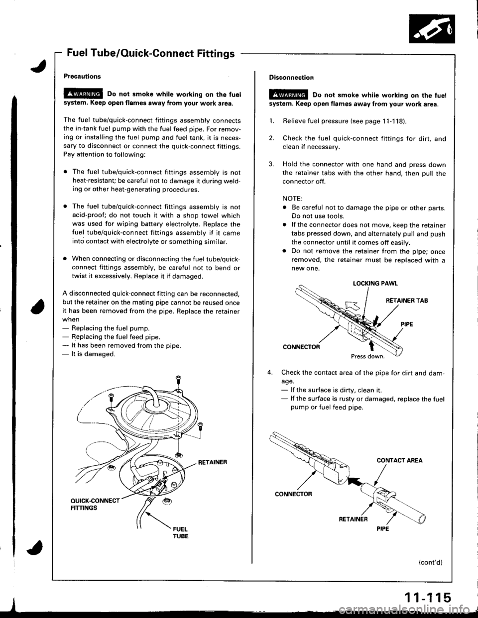
Fuel Tube/Ouick-Connect Fittings
Prgcautions
!@@ Do not smoke while working on the fuel
sysiem. K€ep open flames away from your work area.
The fuel tube/quick-connect fittings assembly connectsthe in-tank tuel pump with the fuelfeed pipe. For remov-
ing or installing the fuel pump and fuel rank, it is neces,sary to disconnect or connect the quick-connect fittings.
Pay attention to following:
r The fuel tube/quick-connect fittings assembly is not
heat-resistanU be careful not to damage it during weld-ing or other heat-generating procedures.
. The fuel tube/quick-connect fittings assembly is not
acid-proof; do not touch it with a shop towel which
was used for wiping battery electrolyte. Replace the
fuel tube/quick-connect fittings assembly if it came
into contact with electrolyte or something similar.
. When connecting or disconnecting the fuel tube/quick-
connect fittings assembly, be careful not to bend or
twist it excessively. Replace it if damaged.
A disconnected quick-connect fitting can be reconnected,
but the retainer on the matlng pipe cannot be reused once
it has been removed from the pipe. Replace the retainer
when- Replacing the fuel pump.- Replacing the fuel feed pipe.- It has been removed trom the oiDe.- lt is damaged.
RETAINER
I
Disconnection
t!!@ Do not smokc white working on the fuel
system. Keep open flames away from your wotk area.
'L Relievefuel pressure (see page 11-118).
2. Check the fuel quick-connect fittings tor dirt, andclean iI necessary.
3. Hold the connector with one hand and press down
the retainer tabs with the other hand, then pull the
connector off.
NOTE:
. Be careful not to damage the pipe or other parts.
Do not use tools.
. lf the connector does not move, keep the retainer
tabs pressed down, and alternately pull and push
the connector until it comes off easily.. Do not remove the retainer from the pipe; once
removed, the retainer must be replaced with a
new one.
LOCKING PAWL
RETAINER TAB
CONNECTOR
Press down,
4,Check the contacl area of the pipe for dirt and dam,
a9e.- lf the surface is dirty, clean it.- lf the surface is rusty or damaged, replace the fuelpump or fuel feed pipe.
(cont'd)
1 1-1 15
PIPE