ground HONDA INTEGRA 1998 4.G Workshop Manual
[x] Cancel search | Manufacturer: HONDA, Model Year: 1998, Model line: INTEGRA, Model: HONDA INTEGRA 1998 4.GPages: 1681, PDF Size: 54.22 MB
Page 1396 of 1681
ra
Troubleshooting Tests
Testing for Voltage
When testing for voltage at a connector
without wire seals, you do not have to
seoarate the two halves of the connector.
lnstead. orobe the connector from the back
Always check both sides of the connector
because dirty, corroded, and bent terminals
can cause problems (no electrical contact =
an open).
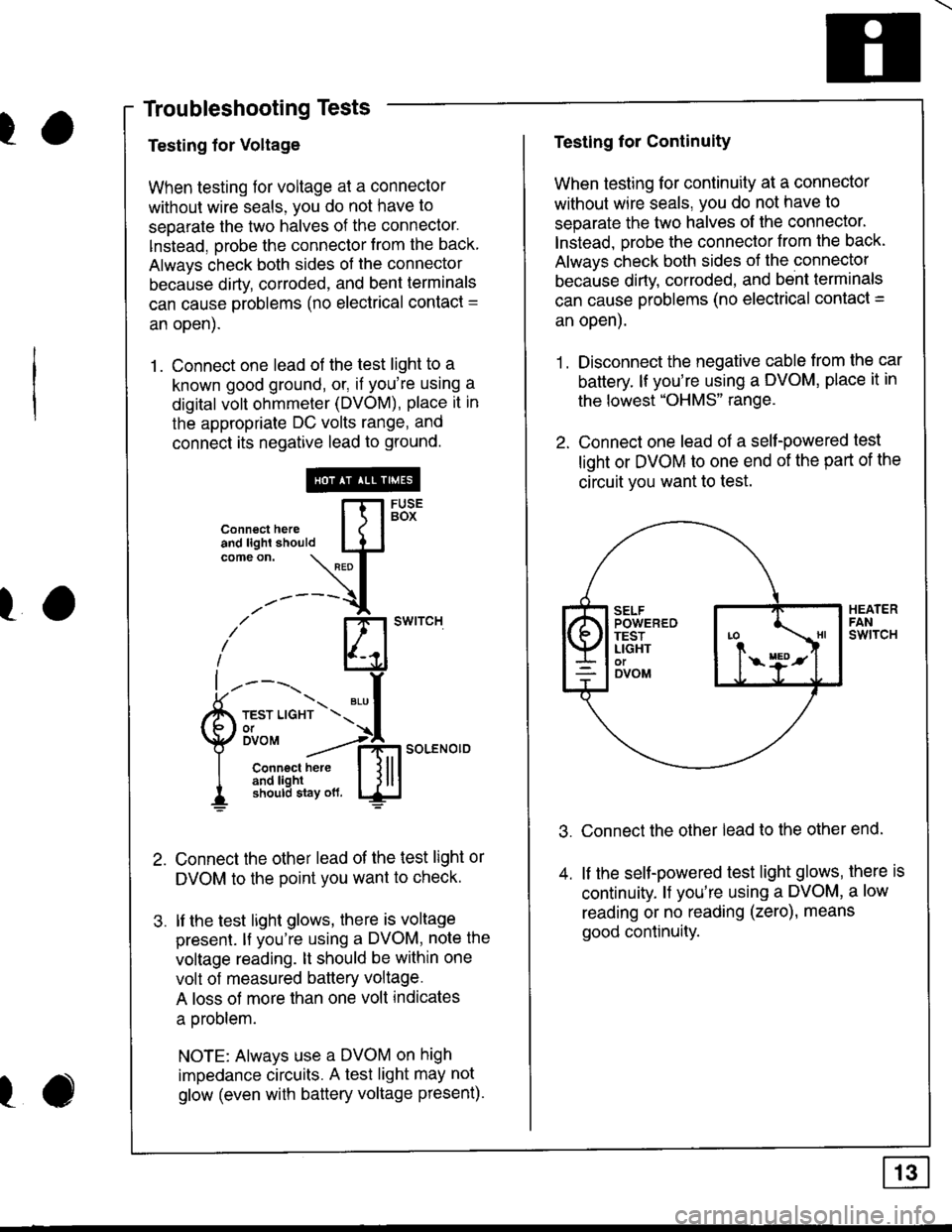
1. Connect one lead of the test light to a
known good ground, or, if you're using a
digital volt ohmmeter (DVOM), place it in
the appropriate DC volts range, and
connect its negative lead to ground.
Connect the other lead of the test light or
DVOM to the point you want to checK.
lf the test light glows, there is voltage
presenl. lf you're using a DVOM, note the
voltage reading. lt should be within one
volt of measured battery voltage.
A loss of more than one volt indicates
a oroblem.
NOTE: Always use a DVOM on high
impedance circuits. A test light may not
glow (even with battery voltage present).
connecthe,e [fl5Bi'
:lL:'#*-'\L{.t
-'-----{
i' El'*''""
L----'t.r- ".,f
Qli'""'"":*soLENo,DI Connect here I l lll
I 3f,3JiEx\",* ljlu
ro
I
Testing for Continuity
When testing for continuity at a connector
without wire seals, you do not have to
separate the two halves of lhe connector'
lnstead. orobe the connector from the back.
Always check both sides of the connectol
because dirty. corroded. and bent terminals
can cause problems (no electrical contact =
an open).
1. Disconnect the negative cable from the car
battery. lf you're using a DVOM, place it in
the lowest "OHMS" range.
2. Connect one lead of a self-powered test
light or DVOM to one end of the part of the
circuit vou want to test.
Connect the other lead to the other end.
lf the seltpowered test light glows, there is
continuity. l{ you're using a DVOM, a low
reading or no reading (zero), means
good continuity.
Page 1397 of 1681
How To Use This Manual
Troubleshooting Tests
Testing for Voltage Drop
Wires, connectors, and switches are designed
to conduct current with a minimum loss of
voltage. A voltage drop of more than one volt
indicates a oroblem.
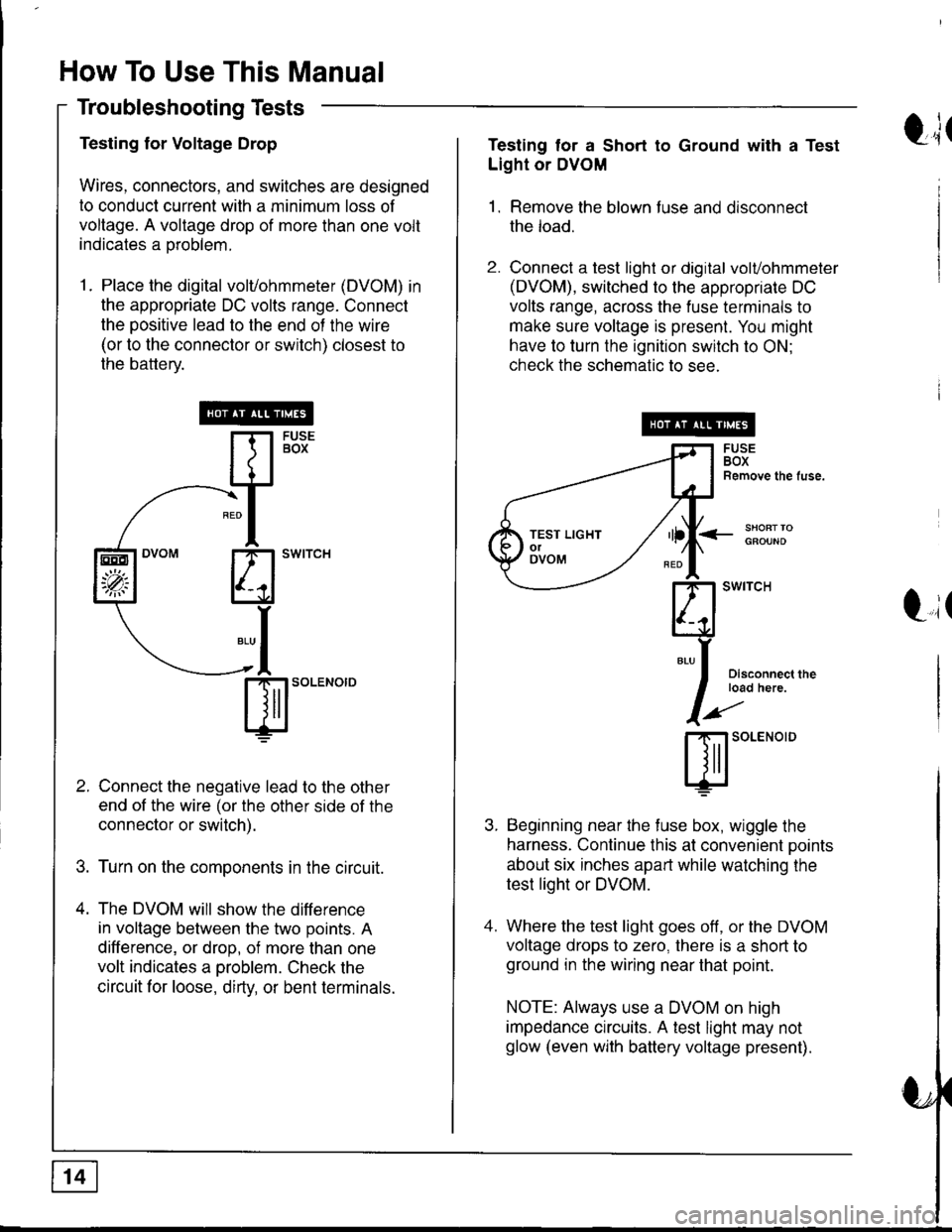
1. Place the digital volvohmmeter (DVOM) in
the appropriate DC volts range. Connect
the positive lead to the end of the wire
(or to the connector or switch) closest to
the battery.
Connect the negative lead to the other
end of the wire (or the other side of the
connector or switch).
Turn on the components in the circuit.
The DVOM will show the difference
in voltage between the two points. A
difference, or drop, of more than one
volt indicates a oroblem. Check the
circuit for loose, dirty, or bent terminals.
sl'o""o'o
EEO
'p;
t;tTesting tor a Short to Ground with a Test
Light or DVOM
1. Remove the blown fuse and disconnect
the load.
2. Connect a test light or digital volvohmmeter
(DVOM), switched to the appropriate DC
volts range, across the fuse terminals to
make sure voltage is present. You might
have to turn the ignition switch to ON;
check the schematic to see.
<_SHOFTTOGFOUND
t,it
I
Disconnect theload here.
SOLENOID
Beginning near the f use box, wiggle the
harness. Continue this at convenient ooints
about six inches apart while watching the
test light or DVOM.
Where the test light goes off, or the DVOM
voltage drops to zero, there is a short to
ground in the wiring near that point.
NOTE: Always use a DVOM on high
impedance crrcuits. A test light may not
glow (even with battery voltage present).
TEST LIGHTolOVOM
Page 1398 of 1681
I
I
I
Testing for a Short to Ground with a
Self-Powered Test Light or DVOM
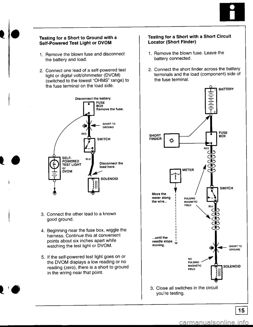
1. Remove the blown fuse and disconnect
the battery and load.
2. Connect one lead of a self-powered test
light or digital volvohmmeter (DVOM)
(switched to the lowest "OHMS' range) to
the fuse terminal on the load side.
Disconnect the battery
FUSEBOXRemove the tuse,
<- li9T:oGFOUND
Disconnect theload here.
.aa'
t-t SoLENOTO
Connect the other lead to a known
good ground.
Beginning near the fuse box, wiggle the
harness. Continue this at convenient
points about six inches apart while
watching the test light or DVOM.
lf the self-powered test light goes on or
the DVOM displays a low reading or no
reading (zero), there is a short to ground
in the wiring near that Point.
SELF-POWEREDTEST LIGHTorDVOM
A
5.
Testing lor a Short with a Short Circuit
Locator (Short Finder)
1. Remove the blown fuse. Leave the
battery connected.
2. Connect the short finder across the battery
terminals and the load (component) side of
the Juse terminal.
BATTERY
SHORTFINDER
...untiltheneedle stopsmoving.
3. Close all switches in the circuit
you're testing.
n
iH"#/ El'*"""'*"
"'-LL
\8
I
"rf--:*ll;"
il,",r. y'l
:[:J"'"
s;.o"*o'o
Page 1406 of 1681
Ground-to-Components I ndex
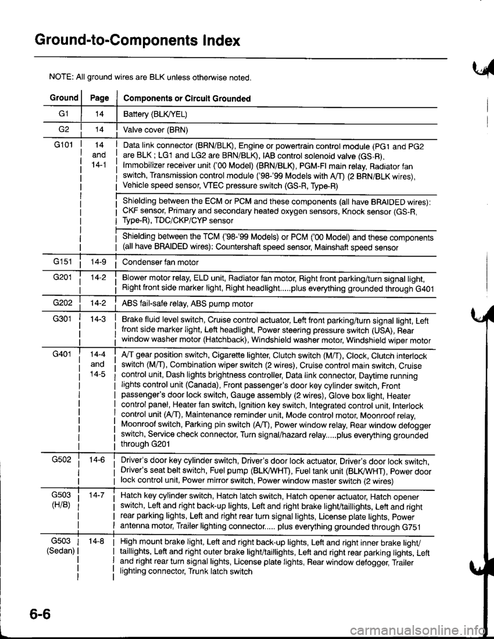
NOTE: All ground wires are BLK unless otherwise noted.
GroundPageComponents or Circuit Grounded
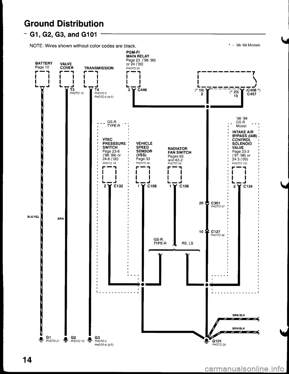
Battery (BLIVYEL)
--t'I Valve cover (BRN)
G101t.+
and
14-1
Daia link connector (BRN/BLK), Engine or powertrain controt module (pct and pG2
are BLK; LG1 and LG2 are BRN/BLR, IAB controt solenoid valve (GS-B),
lmmobilizer receiver unit ('00 Model) (BRN/BLR, PGM-Ft main retay, Radiator fan
switch, Transmission control module ('98.�99 Models with MD (2 BRN/BLK wires),
Vehicle speed sensor, WEC pressure switch (GS-R, Type-R)
Shielding between the ECM or PCM and these components (all have BRAIDED wires):
CKF sensor, Primary and secondary heated oxygen sensors, Knock sensor (GS-R,
Type-R), TDC/CKP/CYP sensor
Shielding between the TCM ('98-'99 Models) or PCM ('00 Model) and these components(all have BRAIDED wires): Countershaft speed sensor, Mainshaft speed sensor
G1s1 ii Condenser fan motor
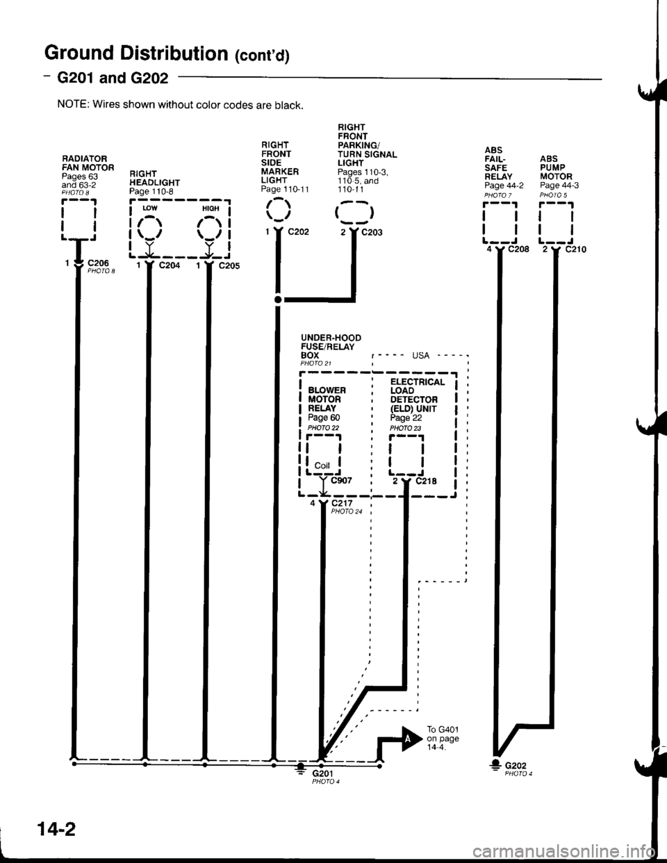
Brake fluid level switch, Cruise control actuator, Left front parking/turn signal light, Left
front side marker light, Left headlight, Power steering pressure switch (USA), Rear
window washer motor (Hatchback), Windshield washer motor, Windshield wiper motor
14-3
Blower motor relay, ELD unit, Badiator fan motor, Right front parking/turn signal light,
Right front side marker light, Right headlight.....plus everything grounded through G401
ABS fail-safe relay, ABS pump motor
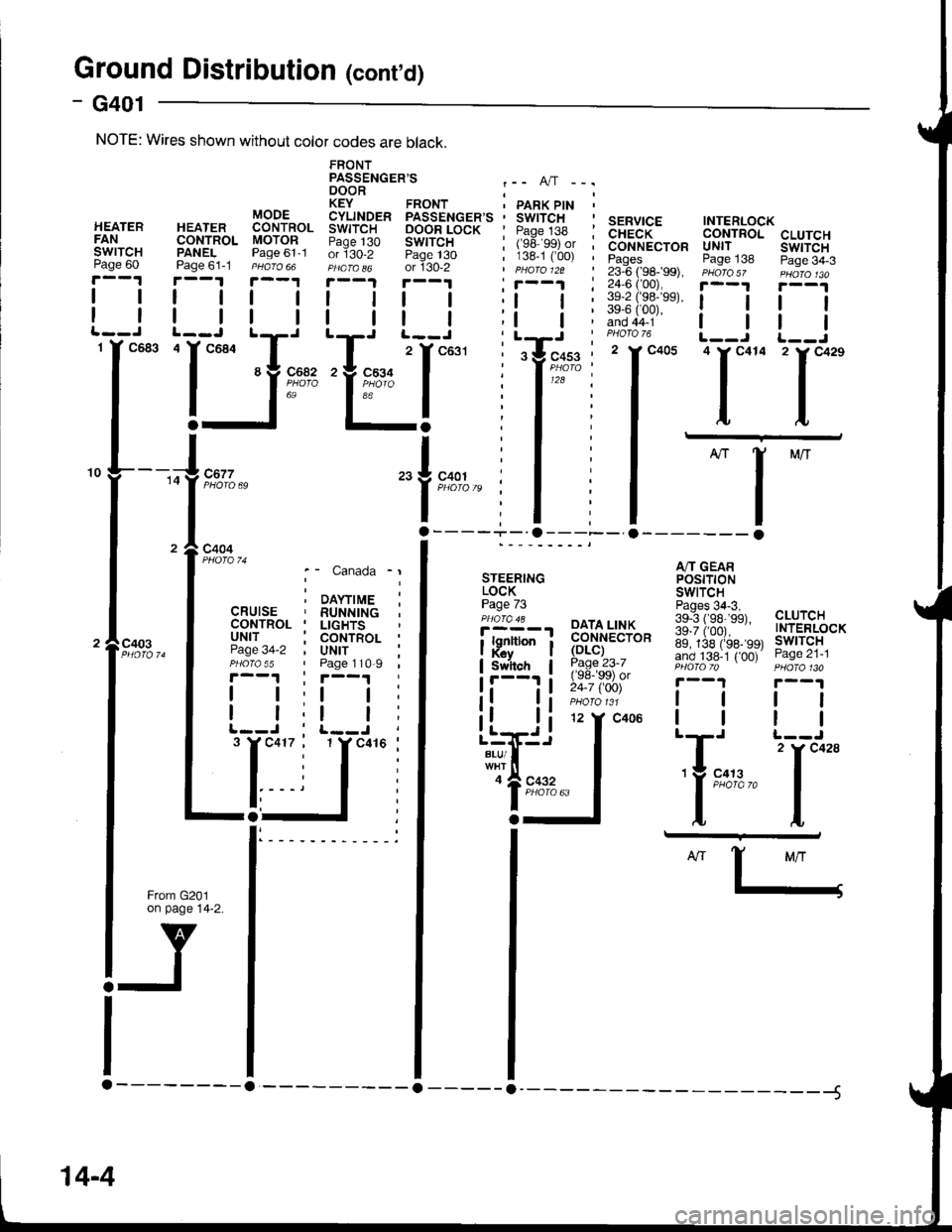
G40114-4
ano
l4-c
A,/T gear position switch, Cigarette lighter, Clutch switch (M,/T), Ctock, Ctutch interlock
switch (MfD, Combination wiper switch (2 wires), Cruise control main switch, Cruise
control unit, Dash lights brightness controller, Data link connector, Daytime running
lights control unit (Canada), Front passenger's door key cylinder switch, Frontpassenger's door lock switch, Gauge assembly (2 wires), Glove box light, Heater
control panel, Heater tan switch, lgnition key switch, Integrated control unit, Interlock
control unit (AfI), Maintenance reminder unit, Mode control motor, Moonroof relay,
Moonroof switch, Parking pin switch (AfD, Power window relay, Rear window defogger
switch, Service check connector, Turn signal/hazard relay.....plus everything grounded
throuoh G201
Driver's door key cylinder switch, Driver's door lock actuator, Drivels door lock switch,Driver's seat belt switch, Fuel pump (BLI(/WHT), Fuel tank unit (BLI(/WHT), power doorlock control unit, Power mirror switch, Power window master switch (2 wires)
Hatch key cylinder switch, Hatch latch switch, Hatch opener actuator, Hatch ooener
switch, Left and right back-up lights, Left and right brake light/taillights, Lett and right
rear parking lights, Left and right rear turn signal lights, License plate lights, power
antenna motor, Trailer lighting connector..... plus everything grounded through G751
6-6
'14-8G503
(Sedan)
High mount brake light, Left and right back-up lights, Lett and right inner brake tighv
taillights, Left and right outer brake light/taittights, Left and right rear parking tights, Leftand right rear turn signal lights, License plate lights, Rear window detogger, Trailer
lighting connector, Trunk latch switch
Page 1407 of 1681
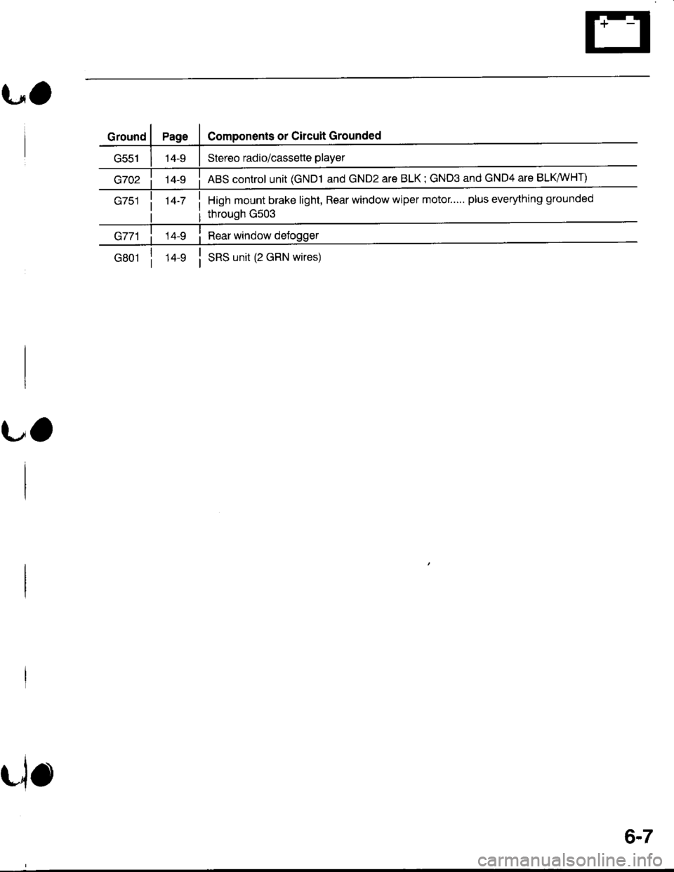
t-,O
i 14-7 i
Components or Circuit Grounded
Stereo radio/cassette player
ABS control unit (GND1 and GND2 are BLK; GND3 and GND4 are BLKWHT)
High mount brake light, Rear window wiper motor..... plus everything grounded
through G503
i Rear window delogger
G801luslSRS unit (2 GRN wires)
UO
rio
6-7
Page 1419 of 1681
TRANSMISSION
I
I
T4
PGM-FIMAIN RELAYPage 23 ('98-'99)or 24 ( 00)
tl
tlL-J
* : '98-'99 Models
i---------\L---------J(- 10) r-- -;-;.11, (c408.)(- 23)10
'98- 99.. GS.R' l/odel
inrrarerrn i
I
I
.-- GS-R. TYPE.R
VEHICLESPEEDSENSORRADIATOBFAN SWITCH
and 63 2
tl
tlL-Jcl08
(vss)Page
PHATO 6IIITJ
I
I
33
I
I
c3o1 ;
10
Ground Distribution
NOTE: Wires shown without color codes are black.
VALVECOVER
I
I
- G1, G2, G3, and G101
I
I
T3
BATTERYPage 10
r-'r
tl
ll'n'
I
I
I
I
I*-*rl
I
I
I
I
! F,to,o^_l1io,o,o *
14
Page 1421 of 1681
Ground Distribution (conrd)
- G201 and G202
NOTE: Wires shown without color codes are black.
BADIATORFAN MOTORPages 63and 63-2
ll
tl
RIGHTHEADLIGHTPage 110-8
RIGHTFRONTSIDEMARKERLIGHTPage 1 10-1 1
RIGHTFRONTPARKING/TURN SIGNALLIGHTPages 110-3,110 5, and110-11
()
ABSFAIL- ABSSAFE PUMPRELAY MOTORPage 44-2 Page 44-3PHO|A 7 PHOIA 5|.--1r--1
I tt I
I tt I
UNDER-HOODFUSE/RELAYBOX .---- USA ----'PHAfa 21
BLowER : aoAb --'
MOTOR ; DETECTORRELAY ' (ELD) UNITPage 60 ' Peq'e 22PIIOTO 22 . PHOTO2Sr--1.|.--1
| | :t I
[g"ri i l--J
Yc$7 ; 2 t'c218 a
;Y;,;-i---l---J
G201
IA Ai
LY___!jjc2061 Y C204
'l 'J"''L--J L-.J4 I' C208 2Y C210
14-2
Pll;**
Page 1423 of 1681
Ground Distributior (cont'd)
- G401
CLUTCHswtTcHPage 34-3
tl
tl
'l**
A/T GEARPOStTTONSWITCH
139""i#;3a, cLUrcH
ig.ii,oor.--" TNTERLOCK
89, 138 (rss- 99t lwlTcHand 138-1 { 00) Page zl-lPHO|OTo PHOfa 130
r--1 r--1
lttl
ttlll-J t--J
| 2 rc428'Y 9:t:,2." I
ttI,L
SERVICE INTERLOCKCHECK CONTROLCONNECTOR UNITPages Page 13823-6 ( 98-�99), PHoro5z24,6 ('00), i--t
iifiii;"' ! !PHOTO 76 L__J'I*- 'l*"
I -
I
-l
ll- o------- o
FRONTPASSENGER'S .-. A,/T -..DOOR ;KEY FRONT ' PARK PtN 'CYLINDER PASSENGER'S ' SWITCHSWITCH OOOR LOCK ' Paqe 138 :Paqe 130 SWITCH I (ge ggt or ior130-2 Page t30 ; 138-1 C00) ,PHafa o6 or 130-2 | pHaro 12a
!.--.! r--1 , r--1 :I | | | ;l | :
| | I | ;t | ;tT' t^-.--i^- , LrJ
"I ^^^-
z
l
t'or' : tY'"*u"" :'Yk91i t ' I'zi :a';"'" I : I
I I :lErl
"1i,.
| .
NOTE: Wires shown without color codes are black.
c403
STEERINGLOCKPage 73'i!Y-', PAIA,LT$
| . i ;;":,;i;
;p,'nron i ffi."ro*Switch I Page 23-7
!'---'' i !i:; iSii'
);
DAYTIMERUNNINGLIGHTSCONTROLUNITPage 110-9
tl
tl
't Y c41(
Canada
\YTIME
Page
I
I12 Y C406
c41
o
a
Llrri.i
i'#!"..,'lgl::""
14-4
Page 1425 of 1681
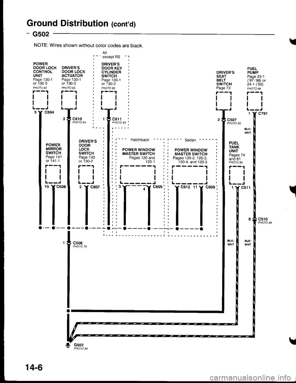
Ground Distribution (conrd)
- Gs02
FUELPUMPPage 23'1('97,'�98) or24 1 ('�00)
tl
tl
98
ORIVER'S PSEAT PiBELT ('IswrTcH 2'page 73 pr
!'--1 7
lll
ttltT' :Tz ! csoz
f
"oto "t
".^
l**' '---- se.ian ------ I
;i rlilFlPOWER WINDOW , f uNtT: : MASTER swtrcH i I F"g"" u+; : Pages 120-2. 120.3. i I ano er120 4. and 120.5 , I photass
':t t;lt I::t l:lt I"L-----J,lL--J
-fl
ll-
' - 31""0, r, - .,
PowER j oRven'sOOOR LOCK DRIVER'S ; DOOR KEY :CONTROL DOOR LOCK , CYLINOER :UNIT ACTUATOR . SWITCHPage 130-1 Page 130-1 : Page 130-1or 130 3 or 130'3 ; or 130-2 :Pnofo u PFofo $ | PtaQfoS5 |r--1 r--1
lttt;tt:
I I I | :t | :
FIFFTo
lTl'lili;-a-- a-- a ---o----a --o----a --
I l._il__-_--
NOTE: Wires shown without color codes are black.
BLlvBLK/c506
! csoz
14-6
Page 1427 of 1681
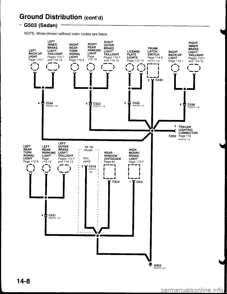
Ground Distributioh (cont'd)
- G503 (Sedan)
NOTE: Wkes shown without color codes are black.
LEFTIN NERBRAKELEFT LIGHT/BACK-UP TAILLIGHTLIGHT Paqes 110-7Paqe 110,1 and 110-13
r-,r ,--r\_,, r- -,
c534
L.JLIJL.J
TRAILERLIGHTINGCONNECTORPage 118
RIGHTINNERBRAKELIGHT/TAILLIGHTPages 110-7and 110-13
()
RrcHr l!-c.{r !'rqlt-
!iTfi^. iff#"" iilt[i",
b:::1,0. ii3:3 :i3::lts'
(:) (:) rllr
TRUNKLATCHswtTcHPage 114-3
tl
tl
2 Y C535
RIGHTBACK-UPLIGHTPage 110 1
/\
LEFTREARTURNSIGNALLIGHTPage 110-5
LEFTREARPARKINGLIGHTPage110-13
/\
LEFTOUTERBRAKELIGHT/TAILLIGHTPages 1'10-7and 110-13
()
'98-'�99
Model
(Notuseo)
cs22
HIGHMOUNTBRAKELIGHTPage 110-7
tl
REARwrNDowDEFOGGERPage 64
ll
14-8