ESP HONDA INTEGRA 1998 4.G Owner's Manual
[x] Cancel search | Manufacturer: HONDA, Model Year: 1998, Model line: INTEGRA, Model: HONDA INTEGRA 1998 4.GPages: 1681, PDF Size: 54.22 MB
Page 700 of 1681
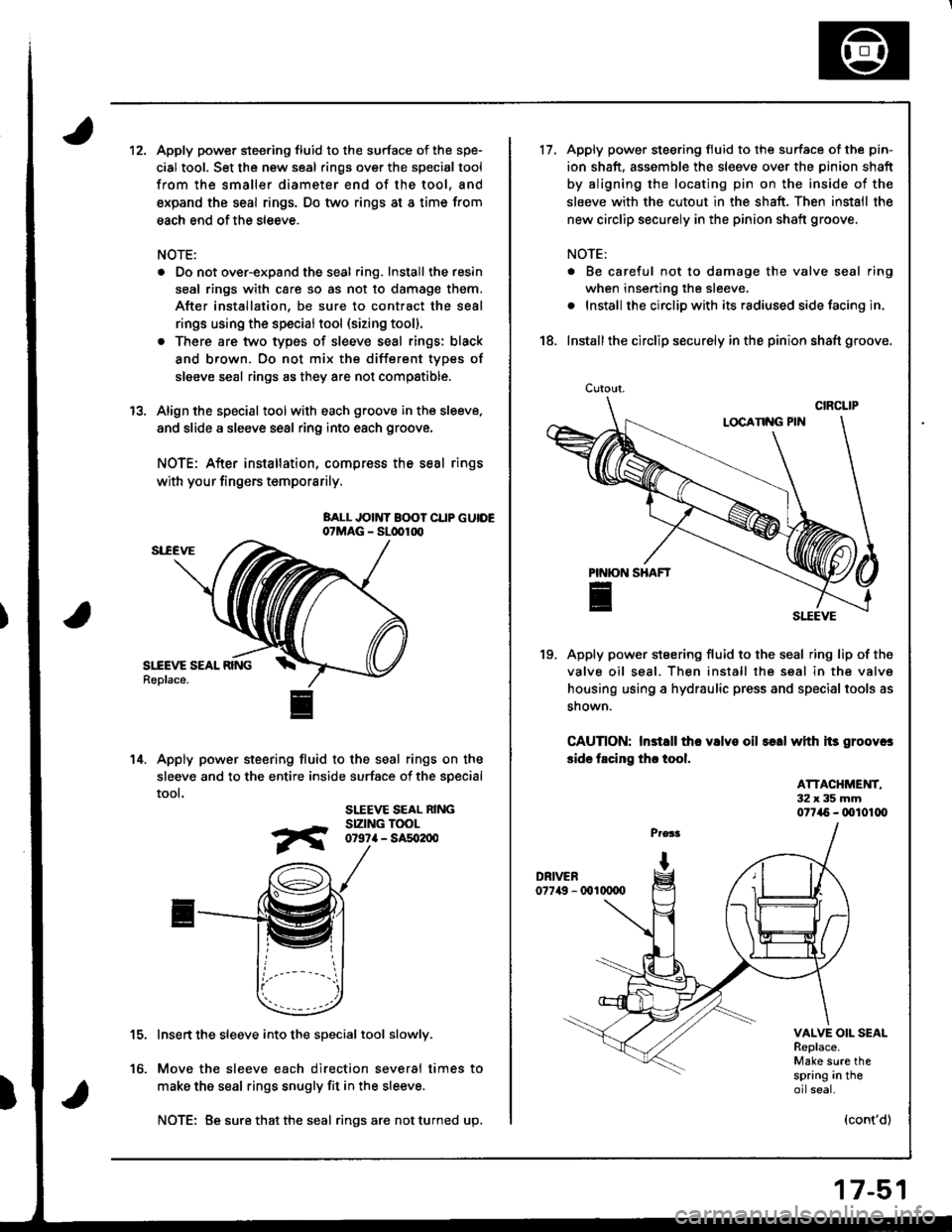
12.Apply power steering fluid to the surface of the spe-
cial tool. Set the new seal rings over the special tool
from the smaller diameter end of the tool, and
expand the seal rings. Do two rings at a time from
each end of the sleeve.
NOTE:
. Do not over-expand the seal ring. Install the resin
seal rings with care so as not to damage them.
After installation, be sure to contract the seal
rings using the specialtool (sizing tool).
. There are two types of sleeve seal rings: black
and brown. Oo not mix the different types of
sleeve seal rings as they are not compstible.
Align the special toolwith each groove in the sleeve.
and slide a sleeve seal ring into each groove.
NOTE: After installation, compress the seal rings
with your fingers temporarily.
BALL JOINT B(X)? CUP GUIDE07MAG - SLdrlrx,
Apply power steering fluid to the seal rings on the
sleeve and to the entire inside surface of the soecial
tool.
SLEEVE SEAL NINGSIZING TOOL0r9?a - sat02n0
Insert the sleeve into the special tool slowly.
Move the sleeve each direction several times to
make the seal rings snugly fit in the sleeve.
NOTE: Be sure that the seal ringsare notturned up.
13.
14.
to.
17-51
Cutout.
17.Apply power steering fluid to the surface of the pin-
ion shaft, assemble the sleeve over the pinion shaft
by aligning the locating pin on the inside of the
sleeve with the cutout in the shaft. Then install the
new circlip securely in the pinion shaft groove.
NOTE:
. Be careful not to damage the valve seal ring
when inserting the sleeve.
. Install the circlip with its radiused side facing in,
18. Installthe circlip securely in the pinion shaft groove.
Apply power steering fluid to the seal ring lip of the
valve oil seal. Then install the seal in the valve
housing using a hydraulic press and special tools as
snown.
CAUnON: Instsll tho valvo oil s€.| with its groovcs
side facing th. tool.
19.
ATTACHMET{T,32x35mm077i15 - (xll01lX,
VALVE OIL SEALReplace.Make sure thespring in theoilseal.
(cont'd)
Page 779 of 1681
IABS Control
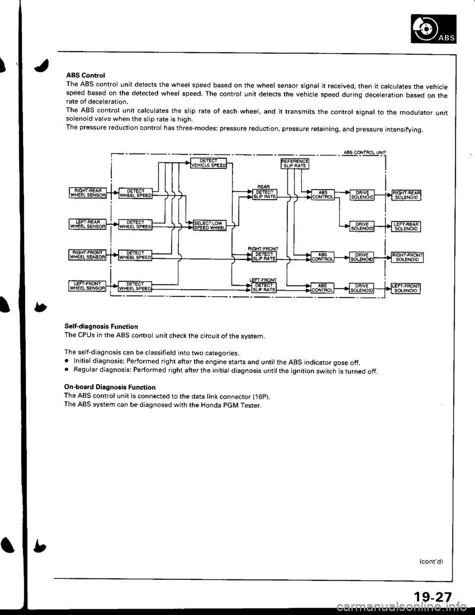
The ABS control unit detects the wheel speed based on the wheel sensor signal it received, then it calculates the vehiclespeed based on the detected wheel speed. The control unit detects the vehicle speed during deceleration based on therate of deceleration.
The ABS control unit calculates the slip rate of each wheel, and it transmits the control signal to the modulator unitsolenoid valve when the slip rate is high.
The pressure reduction control has three-modes: pressure reduction, pressure retaining, and pressure intensifying.
Self-diagnosis Function
The CPUS in the ABS control unit check the circuit of the system.
The self-diagnosis can be classifield into two categories.. Initial diagnosis: Performed right after the engine starts and until the ABS indicator gose off.. Regular diagnosis: Performed right after the initial diagnosis until the ignition switch isturnedoff.
On-board Diagnosis Function
The ABS control unit is connected to the data link connector fi6p).The ABS system can be diagnosed with the Honda PGM Tester.
(cont'd)
19-27
Page 877 of 1681
Rear Window
{
lnstallation
2.
3.
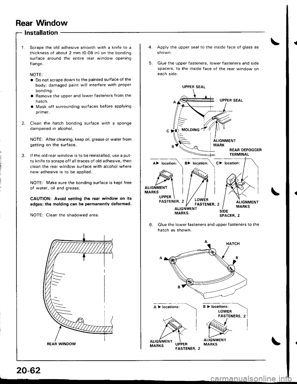
Scrape the old adhesive smooth with a knife to a
thickness of about 2 mm {O.08 in) on the bonding
surface around the entire rear window opening
tlange.
NOTE:
a Do not scrape down to the painted surface of the
body; damaged paint will interlere with proper
bonding.
a Remove the upper and lower fasteners trom the
hatc n.
a Mask oft surrounding surfaces belore applying
primer.
Clean the hatch bonding surface with a sponge
dampened in alcohol.
NOTEr After cleaning, keep oil, grease or water from
getting on the surface.
lf the old rear window is to be reinstalled, use a put-
ty knite to scrape off alltraces of old adhesive, then
clean the rear window surlace with alcohol where
new adhesive is to be applied.
NOTE: Make sure the bonding surface is kept free
of water, oil and grease.
CAUTION: Avoid setling ths rear window on its
edges; the molding can be permanently detormed.
NOTE: Clean the shadowed area.
REAfi WINDOW
20-62
Apply the upper seal to the inside face of glass as
shown.
Glue the upper fasteners, lower lasteners and side
spacers, to the inside face of the rear window on
each side.
UPPER SEAL
MOLDING
5.
ALIGNMENTMARK
REAR DEFOGGERTEEMINAL
C> locaiion:
ALIGNMENTMARKSUPPER
ALIGNMENTMARKSALIGNMENTMARKS
;>t";",i".",
)
SIDESPACER,2
6.Glue the lower lasteners and uooer {asteners to the
hatch as shown.
a > i*"ri".* -\
LOWERFASTENERS, 2I
'N^ |
ALIGNMENTMARKSMARKS
UPPER SEAL
Page 1061 of 1681
Troubleshooting
Tips and Precautions (cont'd)
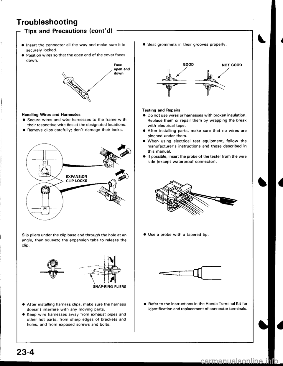
Insert the connector all the way and make sure it is
securely locked.
Position wires so that the open end of the cover faces
down.Faceopen end
V
Handling Wires and Harnesses
I Secure wires and wire harnesses to the frame with
their respective wire ties at the designated locations.
a Remove clips carefully; don't damage their locks.
Slip pliers under the clip base and through the hole at an
angle, then squeez€ the expansion tabs to release the
clro.
sNAP-R|NG PLtERS
After installing harness clips, make sure the harness
doesn't interlere with any moving parts.
Keep wire harnesses away from exhaust pipes and
other hot parts, trom sharp edges ol brackets and
holes, and from exposed screws and bolts.
GOOD NOT GOOD
MA/
lr lr\
Testing and Repairs
a Do not use wires or harnesses with broken insulation.
Replace them or repair them by wrapping the break
with electrical tape.
a Atter installing parts. make sure that no wires are
oinched under them.
a When using electrical test equipment. follow the
manulacturer's instructions and those described in
this manual.
a lI possible, insert the probe of the tester {rom the wire
side {except waterproot connector).
a Seat grommets in their grooves properly.
a Use a probe with a tapered tip.
Reler to the instructions in the Honda Terminal Kit for
identification and replacement oI connector terminals.
23-4
Page 1144 of 1681
J
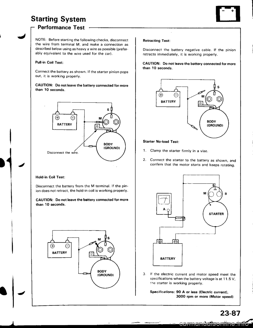
Starting System
Performance Test
NOTE: Before starting the following checks, disconnectthe wire from terminal M, and make a connection asdescribed below using as heavy a wire as possible (prefer
ably equivalent to the wire used for the car).
Pull-in Coil Test:
Connect the battery as shown. If the starter pinion pops
out, it is working properly.
CAUTION: Do not leave the battery connectsd Jor morethan 1O seconds.
Hold-in Coil Test:
Disconnect the battery from the M terminal. lf the pin-
ion does not retract, the hold-in coil is working properly.
CAUTION: Do not leave the battery connected for more
than 10 seconds.
J
Retracting Test:
Disconnect the battery negative cable. lf the pinion
retracts immediately, it is working properly.
CAUTION: Do not leave the battery connected fol more
than 1O seconds.
Starter No]oad Test:
1. Clamp the starter firmly in a vise.
2. Connect the starter to the battery as shown, andconfirm that the motor starts and keeps rotating.
3 lf the electric current and motor soeed meet thespecifications when the battery voltage is at 1 1.5 V,the starter is working properly.
Sp€cifications: 9O A or less (Electric currentl,
3O0O rpm or more {Motor speed}
Page 1153 of 1681
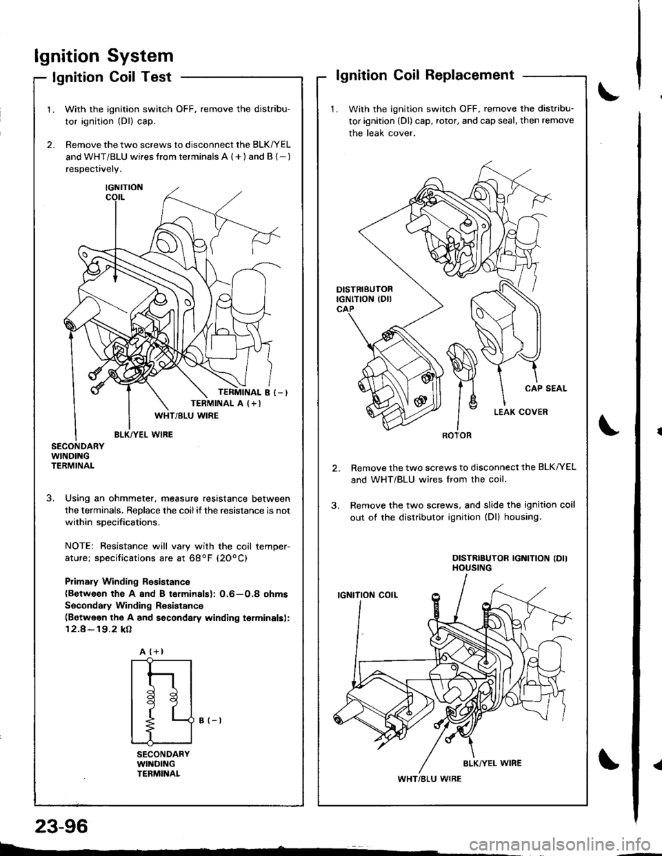
lgnitionSystem
Coil TestlgnitionlgnitionCoilReplacement
1. With the ignition switch OFF, remove the distribu-
tor ignition (Dl) cap, rotor, and cap seal, then remove
the leak cover.
Remove the two screws to disconnect the BLK/YEL
and WHT/BLU wires lrom the coil.
Remove the two screws, and slide the ignition coil
out of the distributor ignition (Dl) housing.
DISTRIBUTOR IGNITION {DIIHOUSING
ROTOR
WHT/BLU WIRE
2.
1.With the ignition switch OFF, remove the distribu-
tor ignition (Dl) cap.
Remove the two screws to disconnect the BLK/YEL
and WHT/BLU wi.es from terminals A ( + ) and B {- )
respectively.
SECONDARYWINDINGTERMINAL
3. Using an ohmmeter, measure resistance between
the terminals. ReDlace the coilif the resistance is not
within soecifications.
NOTE: Resistance will vary with the coil temper-
ature; specifications are at 68oF (20oC)
Plimary Winding Rssistance(Between th€ A 8nd B torminalsl: 0.6-O,8 ohms
Socondary Winding Resistance(Betwe€n the A and secondary winding torminalsl:
12.4-19.2 kA
B (-t
SECONDARYWllrlDlNGTENMINAL
TERMINAL A (+I
A {+}
{
t
l
tl
t9
t
L--
23-96
Page 1178 of 1681
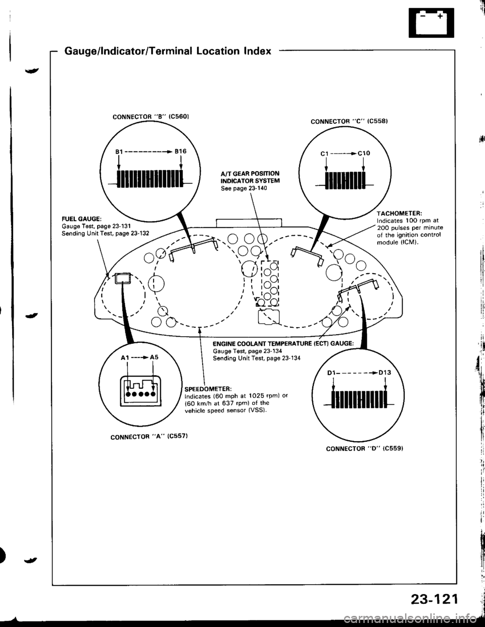
Gauge/lndicator/Terminal Location Index
coNNECTOR "8" (C5601
ltrii
rll
coNNECTOR "C" (Css8l
ACHOMETER:rdicates 10O rpm al
OO pulses per minutef the ignition controlrodule {lCM).
81 ------------ 816
ililllllilll
A,/T GEAR POS]TIONINDICATOR SYSTEMS€e page 23-140
c1 ------>cl0
I
Jilliltl
atespage 23-131t Test, page 23-132
^a1(
u;" u
7' /'- /n.u (,w.--
" oe)\r- -7 ttt'-1 r --
I 'l I z{.-a\y' | \-./^l
!t tr--',9I I l\-//11, I t,-\Jl
.r' to"-ei
I :rl
F<
elrle
ENGINE COOLANT TEMPERATUREGauge T€st, page 23-134Sending Unit Test, page 23'134
IECTI GAUGE:
A1 ----> A5
D1-------->D13
ililtl|illl
SPEEOOMETER:lndicates (60 mph at 1025 rpm) or
{60 km/h at 637 rpm) of the
vehicle speed sensor {VSS).
coNNECTOR "A" (C557)
coNNECTOR "D" (C5591
23-121
Page 1389 of 1681
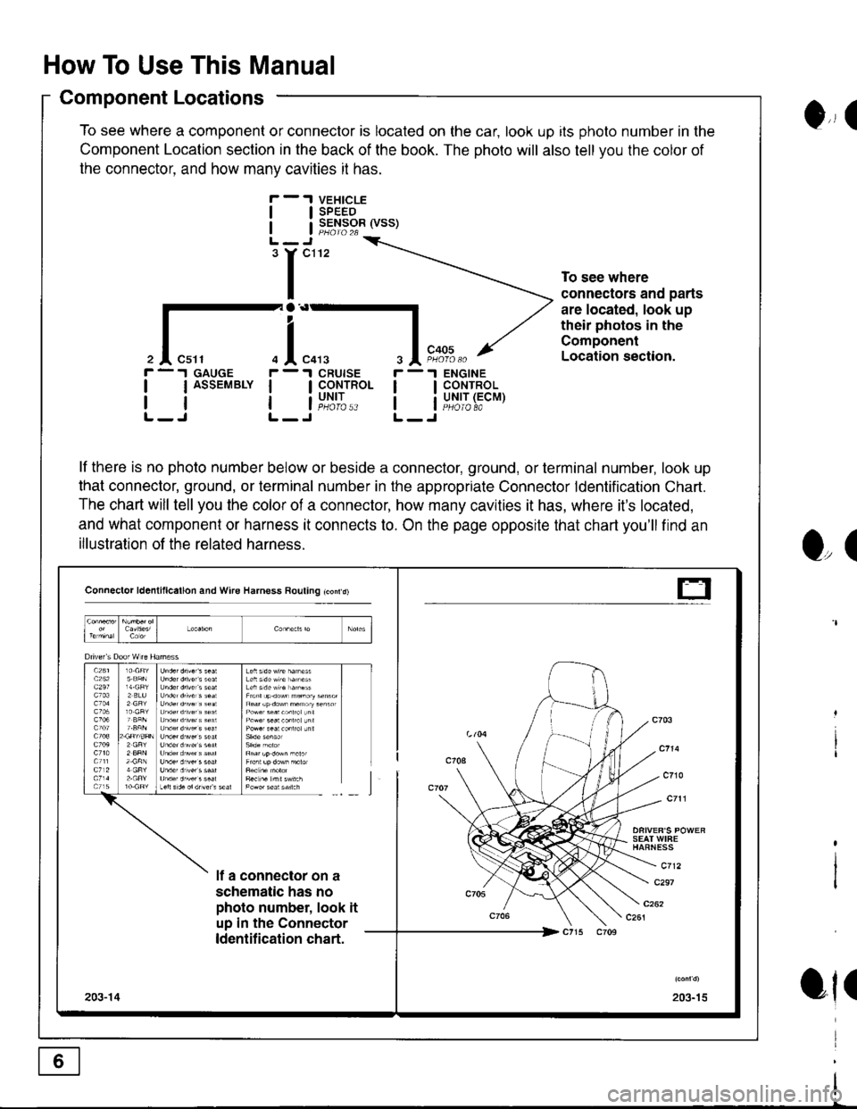
How To Use This Manual
Component Locations
To see where a component or connector is located on the car, look up its photo number in the
Component Location section in the back of the book. The photo will also tell you the color of
the connector. and how manv cavities it has.
VEHICLESPEEDSENSOR (VSS)
ENGINECONTROLUNIT (ECMPHOIO 8A
0,, I
tl
tl
'r"'
To see where
connectors and parts
are located, look up
their photos in the
Component
Location section.
r -.I GAUGE
| | ASSEMBLY I
rtlL-J L-
r -'l
ll
ll
O,(
ot(
il"l,*.I CRUISE
I CoNTROL
i"u,t',:..
lf there is no photo number below or beside a connector, ground, or terminal number, look up
that connector, ground, or terminal number in the appropriate Connector ldentification Chart.
The chart will tell you the color of a connector, how many cavities it has, where it's located,
and what component or harness it connects to. On the page opposite that chart you'll find an
illustration of the related harness.
Connector ld6nlillcallon and Wire Harness Rouling tconrd)
SEAT WIFEHAFNESS
c712lf a connector on a
schematic has no
photo number, look it
up in the Connector
ldentification chart.
c297
203-15203-14
t-
Page 1419 of 1681
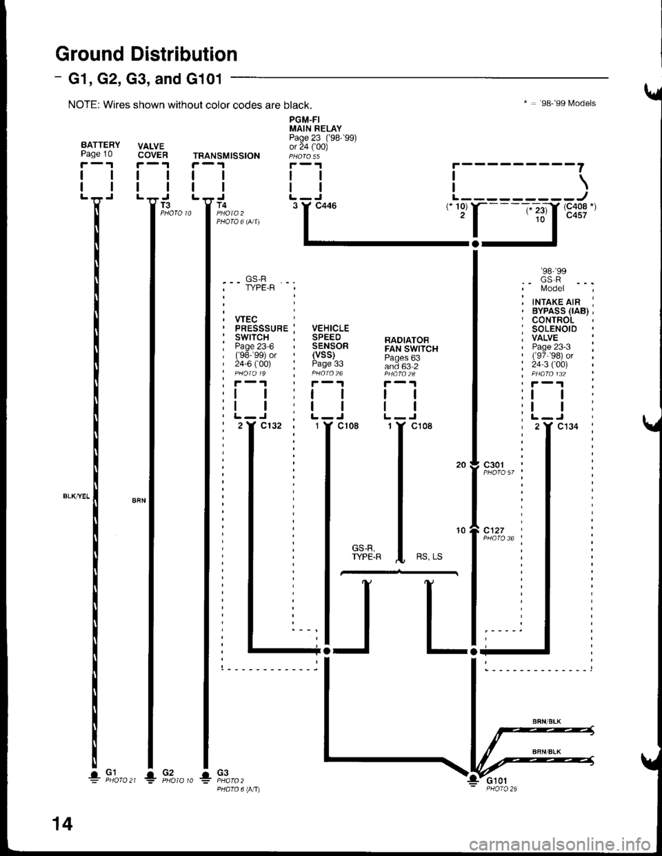
TRANSMISSION
I
I
T4
PGM-FIMAIN RELAYPage 23 ('98-'99)or 24 ( 00)
tl
tlL-J
* : '98-'99 Models
i---------\L---------J(- 10) r-- -;-;.11, (c408.)(- 23)10
'98- 99.. GS.R' l/odel
inrrarerrn i
I
I
.-- GS-R. TYPE.R
VEHICLESPEEDSENSORRADIATOBFAN SWITCH
and 63 2
tl
tlL-Jcl08
(vss)Page
PHATO 6IIITJ
I
I
33
I
I
c3o1 ;
10
Ground Distribution
NOTE: Wires shown without color codes are black.
VALVECOVER
I
I
- G1, G2, G3, and G101
I
I
T3
BATTERYPage 10
r-'r
tl
ll'n'
I
I
I
I
I*-*rl
I
I
I
I
! F,to,o^_l1io,o,o *
14
Page 1451 of 1681
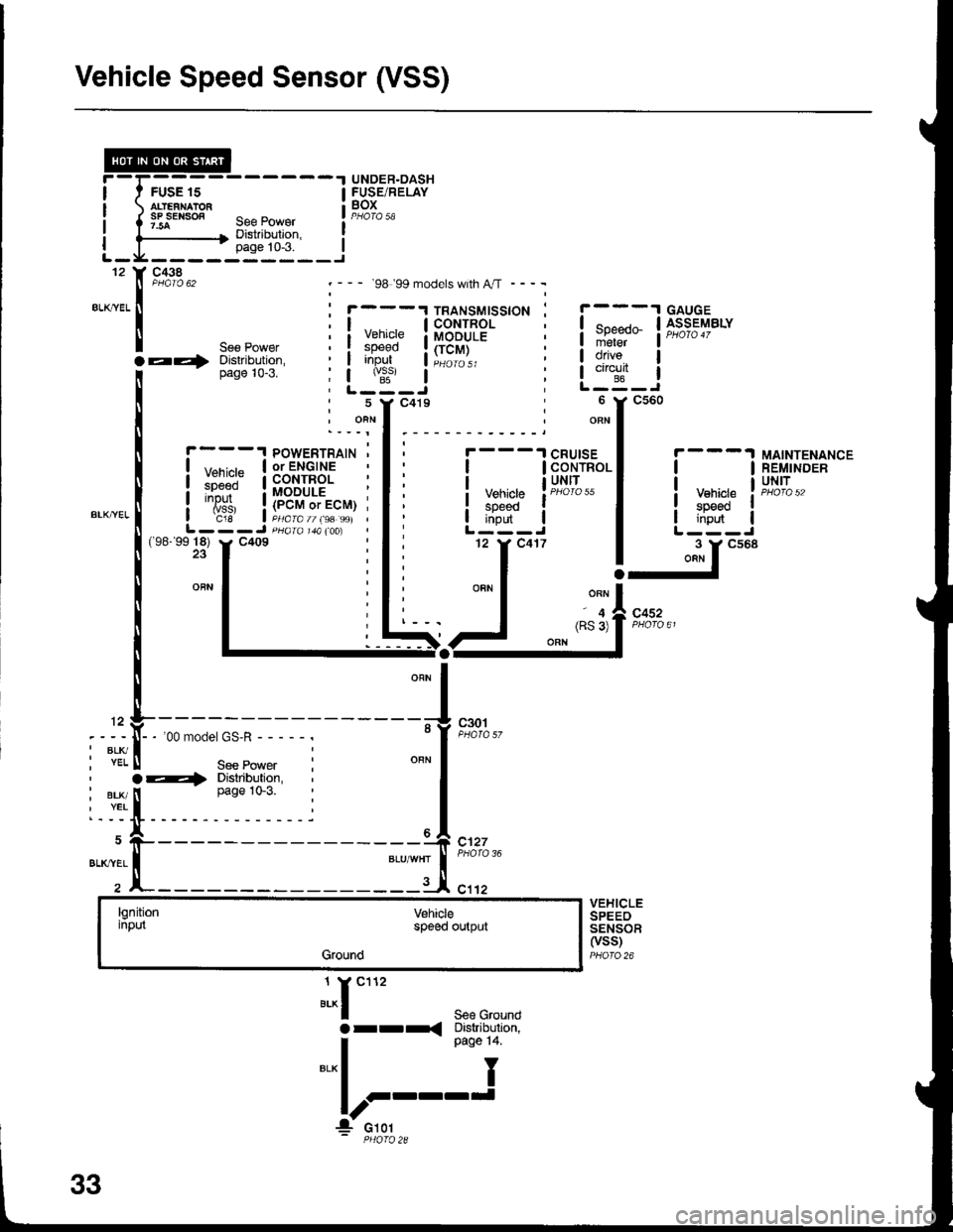
Vehicle Speed Sensor (VSS)
FUSE 15
.t UNDER.DASH
! SBiE/RELAY
'--- 98 99 models with A,rT ----
1
5
J^r""'See Groundarr< Diskibulion,
I o"o" t+
"'*l I
!r::'-'
c438
".,,::.x
POWERTRAIN '| ,,--,^,- | or ENGINEI l:li.:" a coNrRoLi ::J:" : MODULE :
i
'{is,
i!""""9;li"S, j
L---J pHaral&(oo)
ll
Vehiclespeedinput
c30t
CRUISECONTROLUNITtl
! y::g" II i,ifi- |L---J
-ir""'
MAINTENANCEREMINDERUNIT
(98-'9918) y. C409
c452
12
I BLK/. YEL
, BLK/I YEL
BLK'YEL
-'oomodel GS'R-----.
See Powera4 Distribution,
I
ease 1o-3.
x-----
l
c127
c1't2VEHICLESPEEOSENSOF(vss)PHOfO 26
lgnitioninputVehiclespoed output
Ground
33