service HONDA INTEGRA 1998 4.G Workshop Manual
[x] Cancel search | Manufacturer: HONDA, Model Year: 1998, Model line: INTEGRA, Model: HONDA INTEGRA 1998 4.GPages: 1681, PDF Size: 54.22 MB
Page 36 of 1681
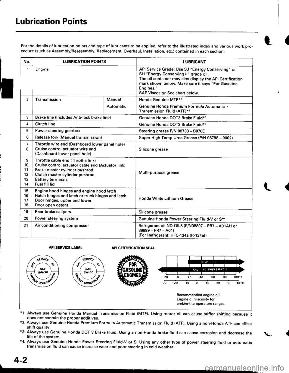
Lubrication Points
No. LUBRICAnON POINTSLUBRICANT
1 E^g,neAPI Service Grade: Use SJ "Energy Conserving" orSH "Energy Conserving ll" grade oil,The oil container may also display the API Certificationmark shown below. Make sure it savs "For GasolineEngines. "
SAE Viscositv: See chart below.
2TransmissionManualHonda Genuine MTF*1
AutomaticGenuine Honda Premium Formula AutomaticTransmission Fluid (ATF)*,
Brake line (lncludes Anti-lock brake line)Genuine Honda DOT3 Brake Fluid13
Clutch lineGenuine Honda DOT3 Brake Fluid*3
Power steering gearboxSteering grease P/N 08733 - 8070E
Release fork lManual transmission)Sup€r High Temp Urea Grease (P/N 08798 - 9002)
1
8
Throttle wire end (Dashboard lower oanel hole)Cruise control actuator wire end(Dashboard lower Danel hole)Silicone grease
o
10
11
14
Throttle cable end (Throttle link)Cruise control actuator cable end (Actuator link)Brake master cvlinder oushrodClutch master cylinder pushrod
Battery terminals
Fuel fill lid
Multi-purpose grease
to
17
18
Engin6 hood hinges and engine hood latchHatch hinges 8od latch or trunk hinges and latchDoor hjnges, upper and lowerDoor ooen detent
Honda White Lithium Grease
19Rear b.ake calipersSilicone grease
20Power steering systemGenuine Honda Power Steering Fluid-V or S*.
21Ai|' conditioning compressorRefrigerant oii ND-O|L8 {P/N38897 - PR7 - A01AH or38899-PR7-A01)(For Refrigerant: HFC-134a (R- 134a))
API SERVICE LABELAPI CERTIFICATION SEAL
Recommended engine oilEngin€ oil viscosity lorambrent lemperature ranges
r(For the details of lubrication points and type of lubricants to be applied, refer to the illustrated index and various work Dro-cedure (such as Assembly/Reassembly, Replacement, Overhaul, Installation. etc.) contained in each section,
*1: Always use Genuine Honda Manual Transmission Fluid (MTF). Using motor oil can cause stiffer shifting because itdoes not contain the proper addtuves.*2: Always use Genuine Honda Premium Formula Automatic Transmission Fluid (ATF). Using a non-Honda ATF can affectshift quality.*3: Always use Genuine Honda DOT 3 B.ake Fluid, Using a non-Honda brake fluid can cause corrosion and decrease thelife of the system.'4: Always use Genuine Honda Power Steering Fluid-V or S. Using any other type of power steering fluid or automatictransmission fluid can cause increase v,/ear and poor steering in cold weather.
L(
{
4-2
Page 45 of 1681
Engine Removal/lnstallation
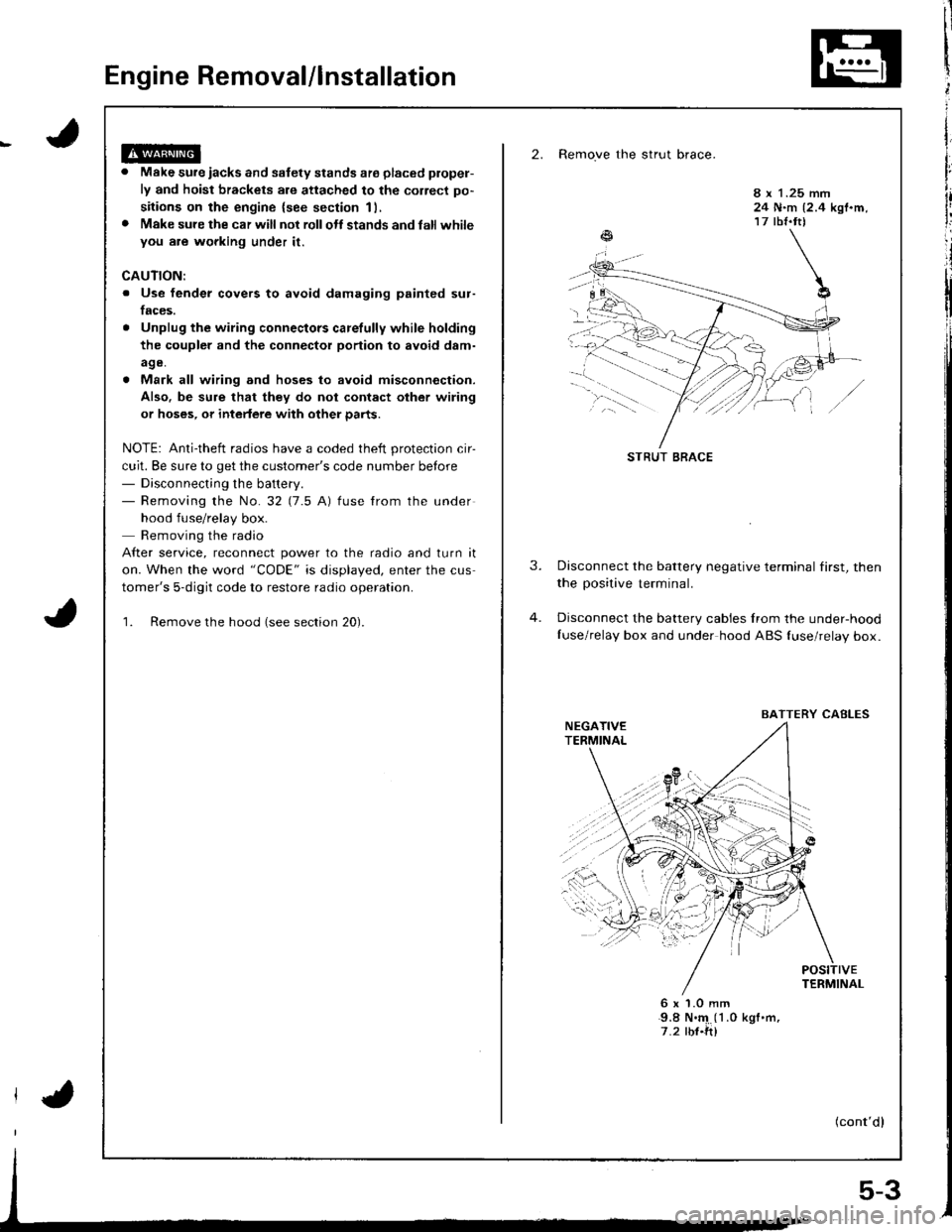
2. Remove the strut brace.
Make sure iacks and safety stands ate placed plopel-
ly and hoist brackets are attached to the correct po-
sitions on the engine {see section 11,
Make sure the car will not rollolt stands and latl whileyou are wgrking under it.
8 x 1.25 mm24 N.m {2.4 kgf.m,17 tbf.tt)
CAUTION:
. Use fender covers to avoid damaging painted sur-
faces.
Unplug the wiring connectors carelully while holding
the coupler and the connector portion to avoid d8m-
age.
Mark all wiring and hoses to avoid misconnection.
Also. be sure that they do not contact other wiring
or hoses, or intedere with other parts.
NOTE: Anti-theft radios have a coded theft protection cir-
cuit. Be sure to get the customer's code number betore- Disconnecting the battery.- Removing the No.32 (7.5 A) fuse from the under
hood fuse/relay box.
Removing the radio
After service, reconnect power to the radio and turn it
on. When the word "CODE" is displayed, enter the cus
tomer's 5-digit code to restore radio operation.
1. Remove the hood (see section 20).
3.Disconnect the battery negative terminal first, then
the positive terminal.
Disconnect the battery cables Irom the under-hood
Iuse/relay box and under hood ABS {use/relay box.
6x1.0mm9.8 N.'4 (1 .0 kgf .m,
7.2 rbf.ft)
(cont'dl
STRUT BRACE
BAITERY CABLES
5-3
Page 86 of 1681
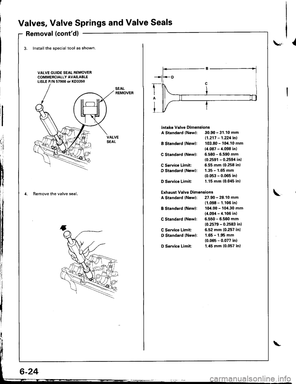
Valves, Valve Springs and Valve Seals
Removal (cont'dl
3. Installthe special tool as shown
VALVE GUIDE SEAL REMOVERCOMMERCIALLY AVAILABLELISLE P/N 57900 or KD3350
.i
'iii
tI
i{
lf
4. Remove the valve seal.
v,l
lntaks valve Dimsnsions
A Standard (Newl: 30.90 - 31.10 mm
B Standard (New):
C Standard {New):
C Sorvice Limit:
D Standard (Now):
D Service Limil:
B Standard (New):
C Standard {N6w}:
C Service Limit:
D Standsrd lNow):
D Servic€ Limit:
11-217 - 1.221inl
103.80 - 104.10 mm
14.087 - 4.098 in)
6.580 - 6.590 mm(0.2591 - 0.2594 in)
6.55 mm (0.258 inl
1.35 - 1.65 mm(0.053 - 0.065 in)'1.15 mm (0.0'15 inl
Exhaust Vslve Dimonsions
A Standard lNew): 27.90 - 28.10 mm\
11.098 - 1.106 in)
1O4.OO - 10,1.30 mm
l,[.09/t - 4.106 in)
5.550 - 6.560 mm
10.2579 - 0.2583 in)
6.52 mm (0.257 inl
1.65 - 1.95 mm
(0.065 - 0.077 in)
1.45 mm (0.057 in)
Page 88 of 1681
Valve Installation'alve Inslallauon -
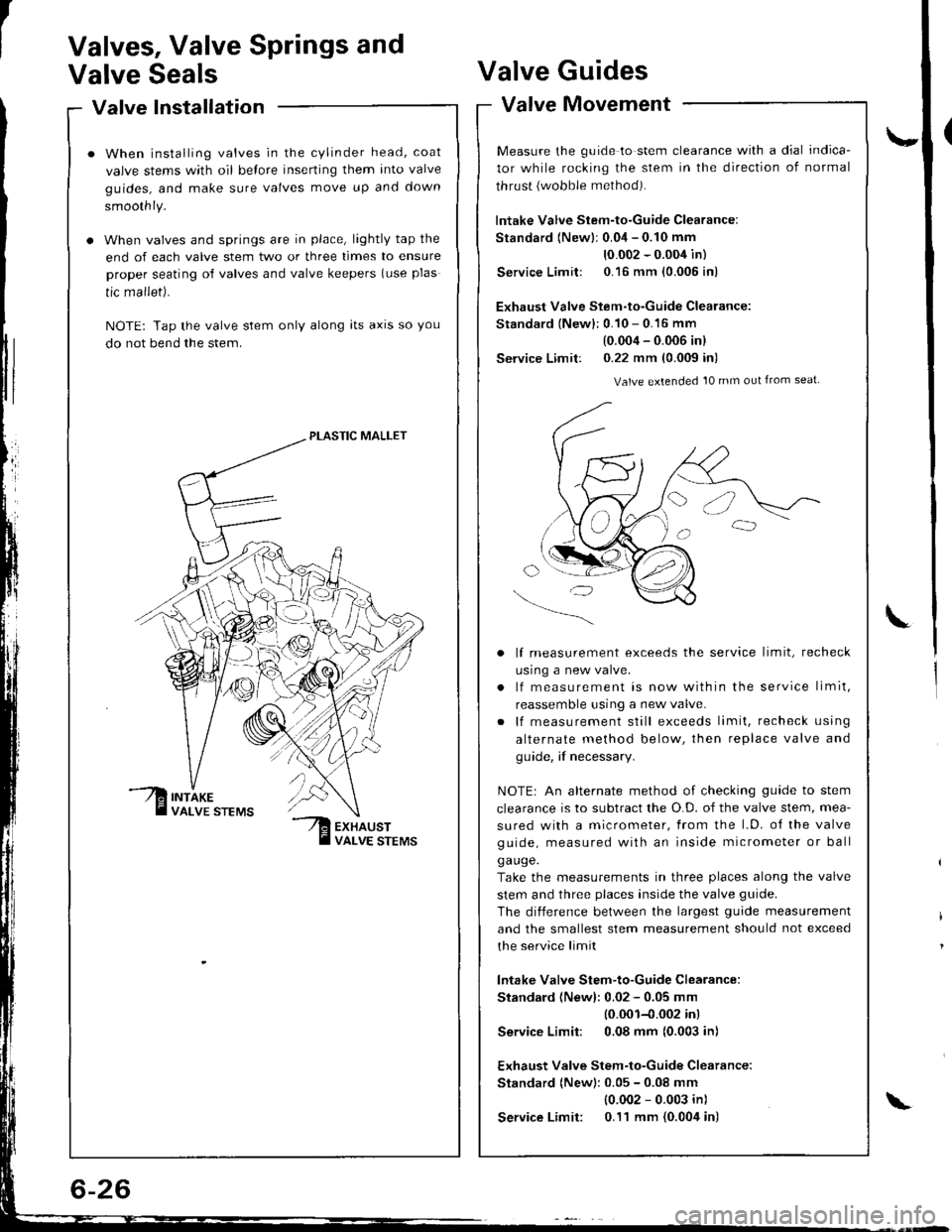
When installing valves in the cylinder head, coat
valve stems with oil belore inserting them into valve
guides, and make sure valves move up and down
smoothly.
When valves and springs are in place, lightly tap the
end of each valve stem two or three times to ensure
proper seating of valves and valve keepers (use plas
tic mallet).
NOTE: Tap the valve stem only along lts axrs so you
do not bend the stem.
PLASTIC MALLET
Valves, Valve Springs and
Valve SealsValve
Valve
Guides
Movement
\-
L
valve tvtovemenr -
Measure the guide to stem clearance with a dial indica-
tor while rocking the stem in the direction of normal
thrust {wobble method).
lntake Valve Stem-to-Guide Clearance:
Standard {Newlr 0.04 - 0.10 mm
10.002 - 0.004 in)
Service Limit: 0.16 mm {0.005 in)
Exhaust Valve Stem-to-Guide Clearance:
Standard {New}: 0.10 - 0.16 mm
(0.004 - 0.006 inl
Service Limit: 0.22 mm (0.009 in)
Valve extended 10 mm out from seat
lf measurement exceeds the service limit, recheck
usrng a new valve.
lf measurement is now within the service limit,
reassemble using a new valve.
lf measurement still exceeds limit, recheck using
alternate method below, then replace valve and
guide, if necessary.
NOTEr An alternate method of checking guide to stem
clearance is to subtract the O.D. of the valve stem, mea-
sured with a micrometer, from the l.D. o{ the valve
guide, measured with an inside micrometer or ball
ga uge.
Take the measurements in three places along the valve
stem and three places inside the valve guide.
The diiference between the largest guide measurement
and the smallest stem measurement should not exceed
the service limit
lntake Valve Stem-to-Guide Clearance:
Standard (Newl: 0.02 - 0.05 mm
10.001-{.002 inl
Service Limit: 0,08 mm (0.003 in)
Exhaust Valve Stem-to-Guide Clearance:
Standard (New): 0.05 - 0.08 mm
{0.002 - 0.003 in)
Service Limit: 0.11 mm {0.004 in)\
Page 91 of 1681
\
Valve Seats
Reconditioning
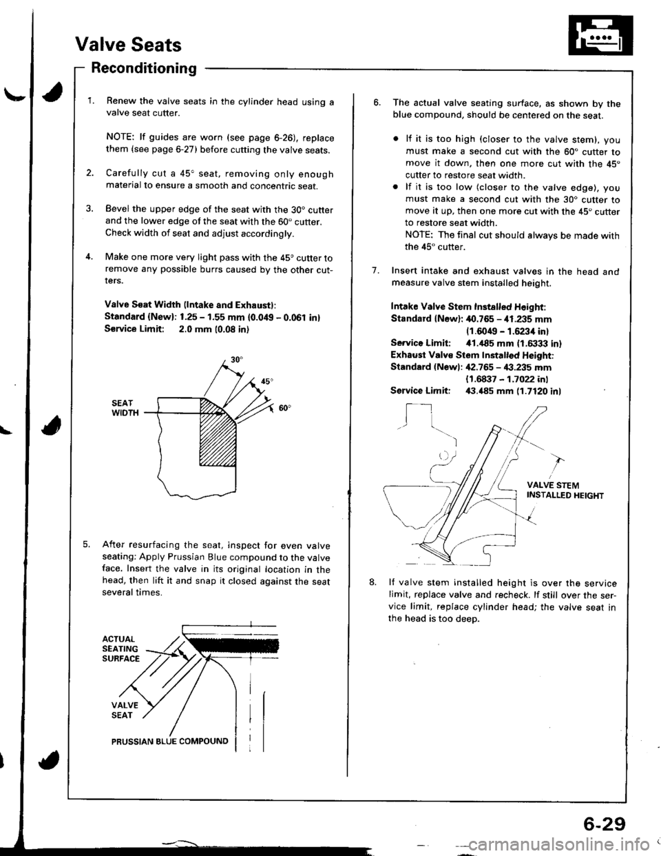
ACTUALSEATINGSURFACE
VALVESEAT
Renew the valve seats in the cylinder head using avalve seat cutter.
NOTE: lf guides are worn (see page 6-26), replace
them {see page 6-27) before cutting the valve seats.
Carefully cut a 45" seat, removing only enoughmaterial to ensure a smooth and concentric seat.
Bevel the upper edge of the seat with the 30. cutterand the lower edge of the seat with the 60. cutter.Check width of seat and adjust accordingly.
Make one more very light pass with the 45o cutter toremove any possible burrs caused by the other cut-rers.
V8lv6 S€at Width (lntake and Exhaustl:
Standard {New}: 1.25 - 1.55 mm {0.0/t{, - 0.061 in}
S€rvice Limit: 2.0 mm 10.08 in)
After resurfacing the seat, inspect for even valveseating: Apply Prussian Blue compound to the valveface. Insert the valve in its original location in thehead, then lift it and snap it closed against the seatseveral times.
PRUSSIAN BLUE COMPOUNO
6-29
o.The actual valve seating surface, as shown by theblue compound, should be centered on the seat.
lf it is too high (closer to the valve stem), you
must make a second cut with the 60" cutter tomove it down, then one more cut with the 45"
cutter to restore seat width.
lf it is too low (closer to the valve edge), you
must make a second cut with the 30. cutter tomove at up, then one more cut with the 45. cutterto restore seat width.
NOTE: The final cut should always be made with
the 45" cutter.
Insert intake and exhaust valves in the head andmeasure valve stem installed height.
Intake Valve Stem Inst8lled Height:
Standard lN6wl: 40.765 - i11.235 mm(1.6049 - 1.6234 in)
Servico Limiti i01.,|85 mm (1.6333 in)
Exhaust Valv€ Stem Installed Height:
Standard {Newl: ,[2.765 - 4:1.235 mm
1.
{1.68i}7 - 1.7022 inl,(1.485 mm 11.7120 inlService Limit:
I_1I
VALVE STEMINSTAI-LED HEIGHT
8.lf valve stem installed height is over the servicelimit, replace valve and recheck. lf still over the ser-vice limit, replace cylinder head; the valve seat in
the head is too deep.
Page 152 of 1681
/
li
l
Main Bearings
Clearance
2.
3.
1.
4.
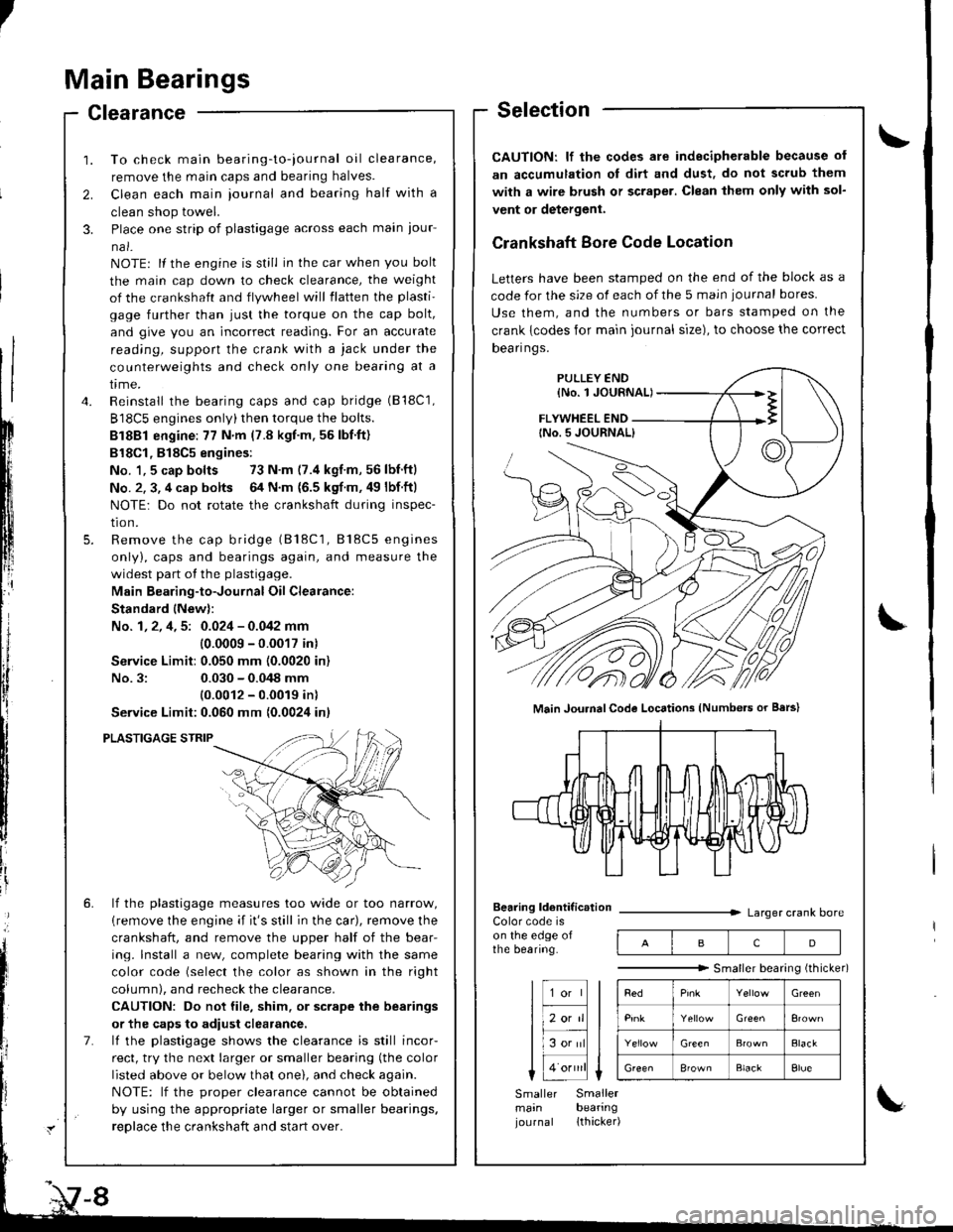
To check main bearing-to-iournal oil clearance,
remove the main caps and bearing halves.
Clean each main iournal and bearing half with a
clean shop towel.
Place one strip of plastigage across each main iour-
na l-
NOTE: lf the engine is still in the car when you bolt
the main cap down to check clearance, the weight
of the crankshaft and flywheel will flatten the plasti'
gage further than just the torque on the cap bolt,
and give you an incorrect reading. For an accurate
reading, support the crank with a jack under the
counterweights and check only one bearing at a
trme.
Reinstall the bearing caps and cap bridge (B18C1,
B18C5 engines only)then torque the bolts.
Bl8Bl engine: 77 N'm (7.8 kgt.m.56lbf.ft)
B18Cl,818C5 engines:
No. 1,5 cap bolts 73 N.m (7.4 kgf.m,56lbnftl
No. 2. 3, 4 cap bolts 64 N.m {6.5 kgf m. 49 lbf ftl
NOTE: Do not rotate the crankshaft during inspec-
tro n.
Remove the cap bridge (818C1, 818C5 engines
only), caps and bearings again, and measure the
widest part of the plastigage.
Main Bearing-to-Journal Oil Clearance:
Standard lNew):
No. 1, 2, 4, 5: 0.024 - 0.042 mm
10.0009 -0.0017 in)
Service Limit:0.050 mm (0.0020 in)
No.3:0.030 - 0.048 mm
10.0012 - 0.0019 inl
Service Limit:0.060 mm {0.0024 inl
PLASTIGAGE STRIP
lf the plastigage measures too wide or too narrow,
{remove the engine if it's still in the car), remove the
crankshaft, and remove the upper half of the bear-
ing. lnstall a new, complete bearing with the same
color code (select the color as shown in the right
column), and recheck the clearance.
CAUTION: Do not file, shim. or scrape the bearings
or the caps to adiust clearance.
lf the plastigage shows the clearance is still incor-
rect, try the next larger or smaller bearing (the color
listed above or below that one), and check again.
NOTE: lf the oroDer clearance cannot be obtained
by using the appropriate larger or smaller bearings.
reolace the crankshaft and start over.
Selection
CAUTION: lf the codes ale indecipherable because of
an accumulation oI dirt and dust, do not scrub them
with a wire bru6h or scraper. Clean lhem only with sol-
vent or detergent.
Crankshaft Bore Code Location
Letters have been stamped on the end of the block as a
code for the size of each of the 5 main iournal bores
Use them, and the numbers or bars stamped on the
crank {codes for main journal size), to choose the correct
Dean nqs,
FLYWHEEL END
Main JouhalCode Locations (Numbe.s or Bars)
Bearing ldentif ic.tionColor code ison the edge ofthe bearing.
Larger crank bore
acD
"""""""" Smallerbearingithicker)
Green
Elack
B'ownBlackElue
Smaller Smallermain bearingjournal lthacker)
Page 153 of 1681
I
IConnecting Rod Bearings
Clearance
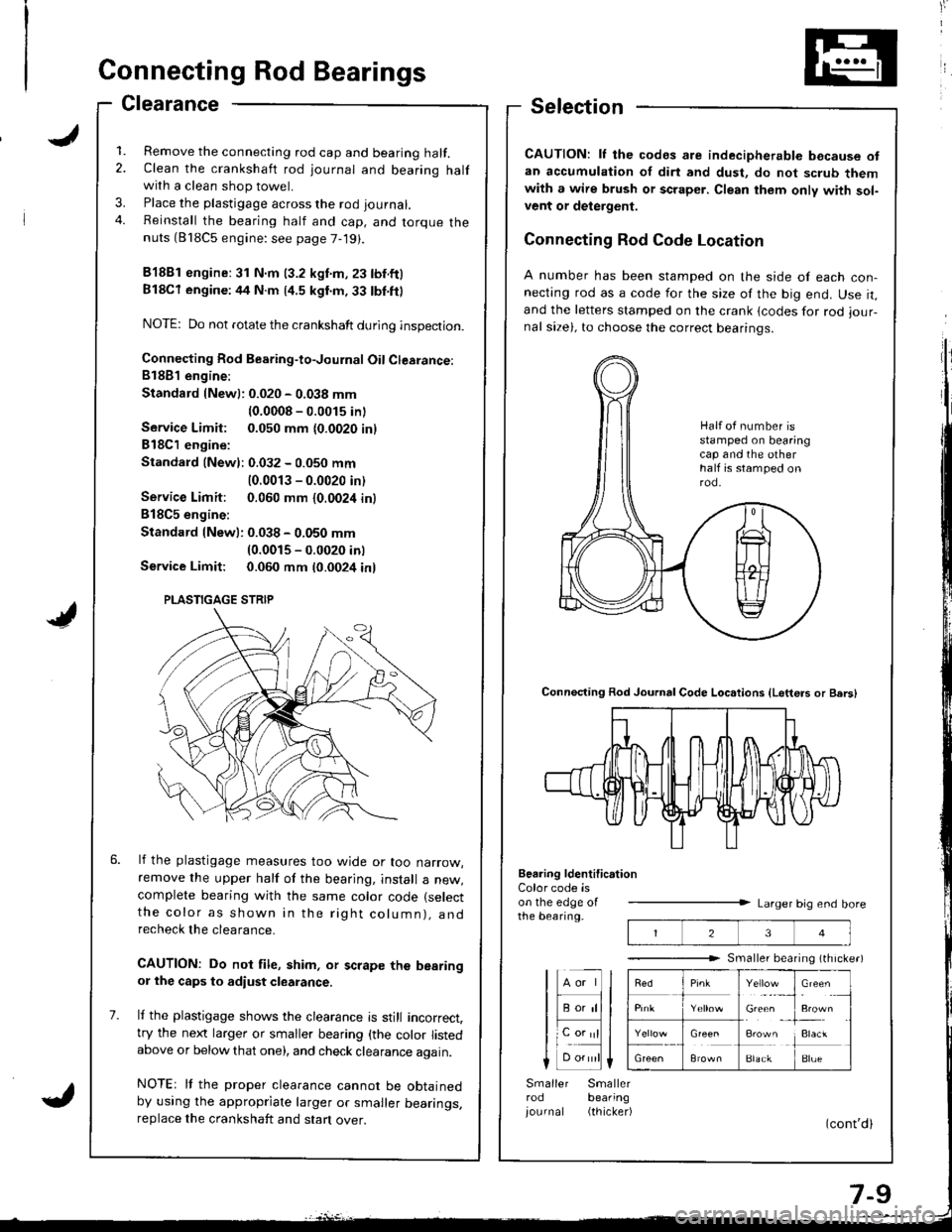
1. Remove the connecting rod cap and bearing half.2. Clean the crankshaft rod journal and bearing halfwith a clean shop towel.
3. Place the plastigage across the rod journal.
4. Reinstall the bearing half and cap, and torque thenuts (818C5 engine: see page 7-19).
81881 engine:31 N.m (3.2 kgnm,23 tbf.ftl
Bl8Cl engine:44 N.m (4.5 kgl.m.33 tbl.ft)
NOTE: Do not rotate the crankshaft during inspection.
Connecting Rod Bearing-to-Journal Oil Clearance:81881 engine:
Standard {Newl: 0.020 - 0.038 mm
{0.0008 - 0.0015 inl
Service Limit: 0.050 mm {0.0020 inl
818C1 engine:
Standald {Newl: 0.032 - 0.050 mm
10.0013 - 0.0020 in)
Service Limit: 0.060 mm {0.0024 in}
B18C5 engine:
Standard lNew): 0.038 - 0.050 mm(0.0015 - 0.0020 inl
Service Limit: 0.060 mm t0.0024 inl
lf the plastigage measures too wjde or too narrow,remove the upper half of the bearjng, install a new,complete bearing with the same color code (select
the color as shown in the rig ht column), andrecheck the clearance.
CAUTION: Do not file, shim, or scrape the bearingor the caps to adiust clearance.
It the plastigage shows the clearance is still incorrect,try the next larger or smaller bearing (the color listedabove or below that one), and check clearance again.
NOTEr It the proper clearance cannot be obtainedby using the appropriate larger or smaller bearings,replace the crankshaft and stan over.
Selection
CAUTION: lf the codes are indecipherable because ofan accumulation of dirt and dust, do not scrub themwith a wire brush or scraper. Clean them only with sol-vent or delergent.
Connecting Rod Code Location
A number has been stamped on the side of each con-necting rod as a code for the size of the big end. Use it,and the letters stamped on the crank lcodes for rod iour-nal size), to choose the correct bearinqs.
Connecting Rod Journal Code Loc.tions {Letters or Bers)
Beering ldentification
23
Y"rl.:_,
Gie& ,
!**
i:1"
BlackBlue
Color code ison the edge oIthe bearing.Larger big end bore
Smaller bearing (th rche.)
lHll
I F;;lll
lL".;|l
Smaller Smallerrod bearing
iournal (thicker)
Half ot number isstamped on bearingcap and the otherhalf is stamped onrod.
PLASTIGAGE STRIP
Page 156 of 1681
Grankshaft
Removal (cont'dl
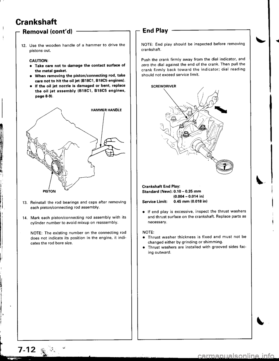
Use the wooden handle ot a hammer to drive the
pistons out.
CAUTION:
. Take care not to damage the contact surface ot
the metal gasket.
. When removing the piston/connecting rod, take
care not to hit the oil iet (818C1, 818C5 enginesl.
. ll the oil iet nozzle is damaged or bent, replace
the oil iet assembly {818C1, B18C5 engincs.
page 8-9).
Reinstall the rod bearings and caps after removing
each piston/connecting rod assembly.
l\4ark each piston/connecting rod assembly with its
cylinder number to avoid mixup on reassembly.
NOTE; The existing number on the connecting rod
does not indicate its position in the engine, it indi-
cates the rod bore size.
End Play
NOTE: End play should be inspected before removing
crankshaft.
Push the crank firmly away from the dial indicator, and
zero the dial against the end of the crank. Then pull the
crank firmly back toward the indicator; dial reading
should not exceed service limit.
Crankshaft End Play:
Standard (New): 0.10 - 0.35 mm
{0.00'l - 0.014 inl
Service Limit: 0.45 mm 10.018 inl
. lf end play is excessive, inspect the thrust washers
and thrust surface on the crankshaft. Replace parts as
necessary.
NOTE:
. Thrust washer thickness is tixed and must not be
changed either by grinding or shimming.
. Thrust washers are installed with grooved sides fac-
ing outward.
12.
14.
Frlfll
ftl
t
iffi[l
t,,tlr
lt
i
Page 157 of 1681
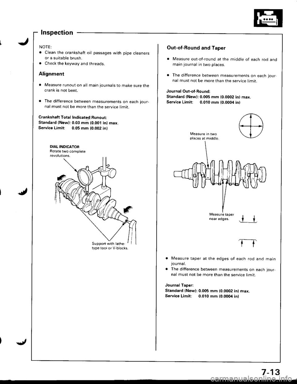
NOTE:
. Clean the crankshaft oil passages with pipe cleanersor a suitable brush.
. Check the keyway and threads.
Alignment
. Measure runout on all main journals to make sure thecrank as not bent.
. The difference between measurements on each ,our-nal must not be more than the service limit.
Crankshaft Total Indicated Runout:
Standard (New): 0.03 mm (0.001 inl max.Service Limit: 0.05 mm 10.002 in)
DIAL INDICATORRotate two complete
Suppon with lathe-type toolor V-blocks.
Out-of-Round and Taper
. Measure out-of-round at the middle of each rod andmain journal in two places.
. The difference between measurements on each jour
nal must not be more than the service limit.
Journal Out-oI-Round:
Standard {Newl:0,005 mm (0.0002 inl max.
Service Limit: 0,010 mm {0.0004 inl
places at middle.
Measure tapernear edges..r +
. Measure taper at the edges of each rod
JOUrnal.. The difference between measurements on
nal must not be more than the service limit.
Journal Taper:
Standard {New): 0.005 mm (0.0002 in) max.
Service Limit: 0.010 mm 10.0004 inr
and matn
each Jour-
7-13
Page 158 of 1681
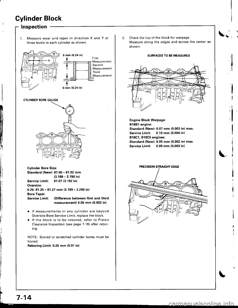
Cylinder Block
Inspection
1. Measure wear and taper in direction
three levels in each cylinder as shown.
XandYat
{0.24 in}6mm
tFirst
Second
ThirdMeasurement
6 mm 10.24 in)
CYLINDER BORE GAUGE
Cylinder Bore Size:
Standard (N€w): 81.00 - 81.02 mm
(3.189 - 3.190 inl
Service Limit: 81.07 (3.192 inl
Oversize:
0.251 81.25 - 41.27 mm 13.199-3.200 inl
Bore Taoer:
S€rvice Limit: lDifference betwcen first and third
measu;ement) 0.05 mm (0.002 inl
. lf measurements in any cylinder are beyond
Oversize Bore Service Limit, replace the block.
. lf the block is to be rebored, reler to Piston
Clearance Inspection (see page 7-16) after rebor-
I ng.
NOTE: Scored or scratched cylinder bores must be
noneo,
Reboring Limit: 0.25 mm (0.01 inl
ll
:i
I
I
Check the top oI the block for warpage.
Measure along the edges and across the center as
sh own.
SURFACES TO 8E MEASURED
Engine Block Warpage:
B188l engine:
Standard {New}: 0.07 mm (0,003 inl max.
Service Limit: 0.10 mm {0.004 in)
818C1, 818C5 engines:
Standard (Newl:0.05 mm 10.002 inl max.
Service Limit: 0.08 mm (0.003 in)
I
I
rl
LC
'/rz
PRECISION STRAIGHT EDGE