indicator HONDA INTEGRA 1998 4.G Owner's Manual
[x] Cancel search | Manufacturer: HONDA, Model Year: 1998, Model line: INTEGRA, Model: HONDA INTEGRA 1998 4.GPages: 1681, PDF Size: 54.22 MB
Page 483 of 1681
Electrical Troubleshootin g
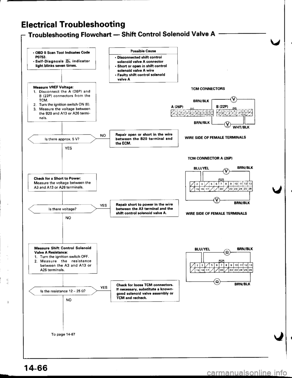
Troubleshooting Flowchart - Shift Gontrol Solenoid Valve A
,
Possiblc Cause
. Dbconnoctod shift controlsolonoid vrlv€ A conneclot. Short or oDen in 3hift controlsolenoid valve A wire. Faulw 3hift control solanoid
Morsure VREF Vohag6:1. Disconnect the A (26P) andB (22P) connectors trom theTCM,2. Turn the ignition switch ON (ll).
3. Measure the voltage betweenthe 820 and A13 or 426 termi-nals.
TCM CONNECTORS
WIRE SIDE OF FEMALE TERMINALS
WIRE SIDE OF FEMALE TERMINALS
14-66
TCM CONNECTOR A (26PI
. OBD ll Scan Tool Indicat . Codem7$.. Self-Diagnosis E indicatorligln blinb sovon times.
Repair open or 3hort in the wirobetwoon tho 820 terminal 3nd
the ECM.ls there approx. 5 V?
Chock lol a Short to Power:Measure the voltage between the
43 and Al3 or 426terminals.
Repail short to powgr in the wirebelwoon the A3 termin.l and th6shift control solonoid valvo A.
Measure Shift Contlol SolenoidValvo A R63btenc.:1. Turn the ignition switch OFF.2. Measure the resista ncebetween the 43 and A13 or426 torminals.
Chock for loo3. TCM connectors.ll nec€ssary, 3ubsthute a known-good solenoid v.lve sssombly orTCM and r6check.
ls the resistance 12 - 25 O?
To page 14-67
Page 485 of 1681
Electrical Troubleshootin g
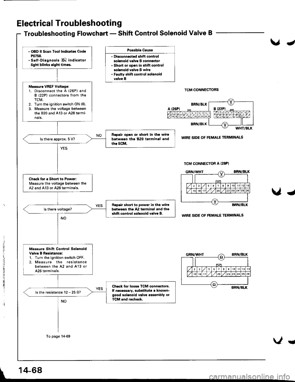
Troubleshooting Flowchart - Shift Control Solenoid Valve B
Po3sibl. Cauao
' Diaconncctad ahift controlsolanoid valve B connoc'tor. Short ol op.n in shift contlolsolanoid valvo B wiro. Faulty lhift control solonoidvalvo B
TCM CONNECTORS
WIR€ SIDE OF FEMALE TERMINALS
WIRE SIDE OF FEMAI."E TERMII{ALS
Me.sure Shift Control Solenoidvalvo B Raliatanco:l. Turn the ignition switch OFF.2. Measure the resistancebetween the 42 and A'13 orA26 terminals.
J
Ug
TCM CONNECTON A (26PI
. OBD ll Scan Tool Indicrt.3 Codem758.. sell"Diagnosi3 [Q indicatorlight blink3.igl|ttlm.!.
Moasur. VREF Voh.go:1. Disconnect the A (26P) andB (22P) connectors from thoTCM.2. Turn the ignition switch ON (lll.
3. Measure the voltage betweenthe 820 and Al3 or A26 termi-nals.
R.pair opan or 3hort in thc wirab.twrqn th. 820 tormin.l and
th. ECM.ls there approx. 5 V?
Check for . Short to Powor:Measure the voltage bstween theA2 and A13 or 426termin8ls.
Rapair Bhort to power in tho wilobotwecn thr 42 laiminal and th.3hift control solanoid valvo B.
Chack lor loos. TCM connactoB.lf n.ceasary, subsiituto a known-good sol.noid valv6 tasambly olTCM rnd rech.ck.
ls the resistance 12 - 25 O?
To page 14-69
Ug
Page 491 of 1681
Electrical Troubleshooting
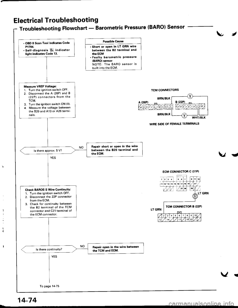
Troubleshooting Flowchart - Barometric Pressure (BARO) Sensor
t\l,
l
'|
. OBD ll Scan Tool lndicatos Code
P1794.. Self-diagnosis El indicator
light indicatos Code 13.
Check BAROS S Wire ContinuitY:1. Turn the ignition switch OFF.
2. Disconnect the 22P connedortrom the ECM.3. Check for continuity betweenthe 82 terminal ot the TCM
connector and C21 terminal of
the ECM connector.
PGsible cau3€
' Short ot oDen in LT GRN wite
betwoen the 82 lcrminal and
ihe ECM. Faulty baromotric PrelsureIBAROI ignsolNOTE: Tho BAFO sensor is
built into the ECM.
VqJ
WIRE SIDE OF FEMALE TERMINALS
Measure VREF Volttge:1. Turn the ignition switch OFF.
2. Disconnect the A (26P) and B(22 P) connectors from the
TCM.3. Turn the ignition switch ON {ll}.
4. Measure the voltage between
the 820 and 413 or 426 termi-
nals,
Repair shon or oPen in the wite
betwcon the 820 tsrminal and
tho EcM.ls there approx.5 V?
Repair open in the wiro betwoon
the TcM and ECM.ls there continuity?
To page 14-75
14-74
V!
Page 498 of 1681
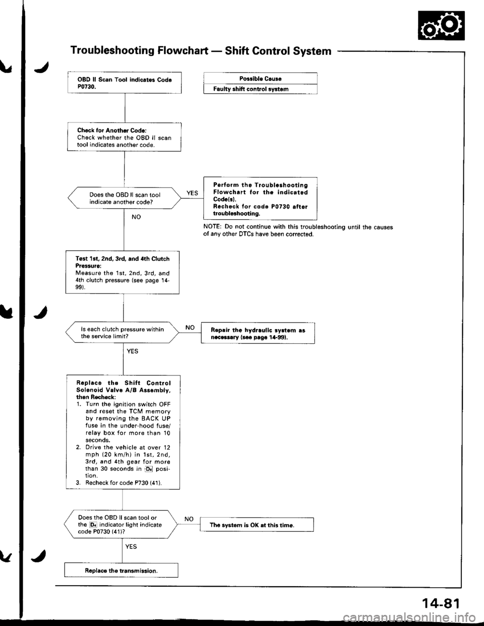
Troubleshooting Flowchart - Shaft Control System
NOTE: Do not continue with this troubleshootlng until the causesof any other DTCS have been corrected.
Chock foi Another Code:Check whether the OBD ll scantool indicates another code.
Psrtorm tho Tioubla3hootingFlowch.rt fo. th. indicatodCodcl.l.Rechsck tor code P0730 attoltroublolhooting.
Does the OBD ll scan toolindicate anothor code?
Tost 1st, 2nd, 3rd, and 4th ClutchProssuro:Measure the 1st,2nd,3rd, and4th clutch pressure (see page 14-
ls each clutch pressure withinthe service limit?R.p!ir lhG hydraulic ry3t.m ranac.3!.ry l3€e pago 1+991.
Roplace the Shilt ContiolSolonoid Valve A/B Assombly,thon Recheck:1. Turn the ignition switch OFFand reset the TCM memoryby removing the BACK UPfuse in the under-hood fuse/relay box for more than '10
seconds.2. Orive the vehicle at over 12mph (20 km/h) in lst,2nd,3rd, and 4th gear for morethan 30 seconds in E posi-tion.3, Recheck for code P730 (41).
Does the OBD llscan toolorthe E indicator light indicatecode P0730 (4'1)?Tho systom is OX etthi3 timo.
Poitible C.uBe
F""lty "hlft ".^t..t ",/"t".
Page 499 of 1681
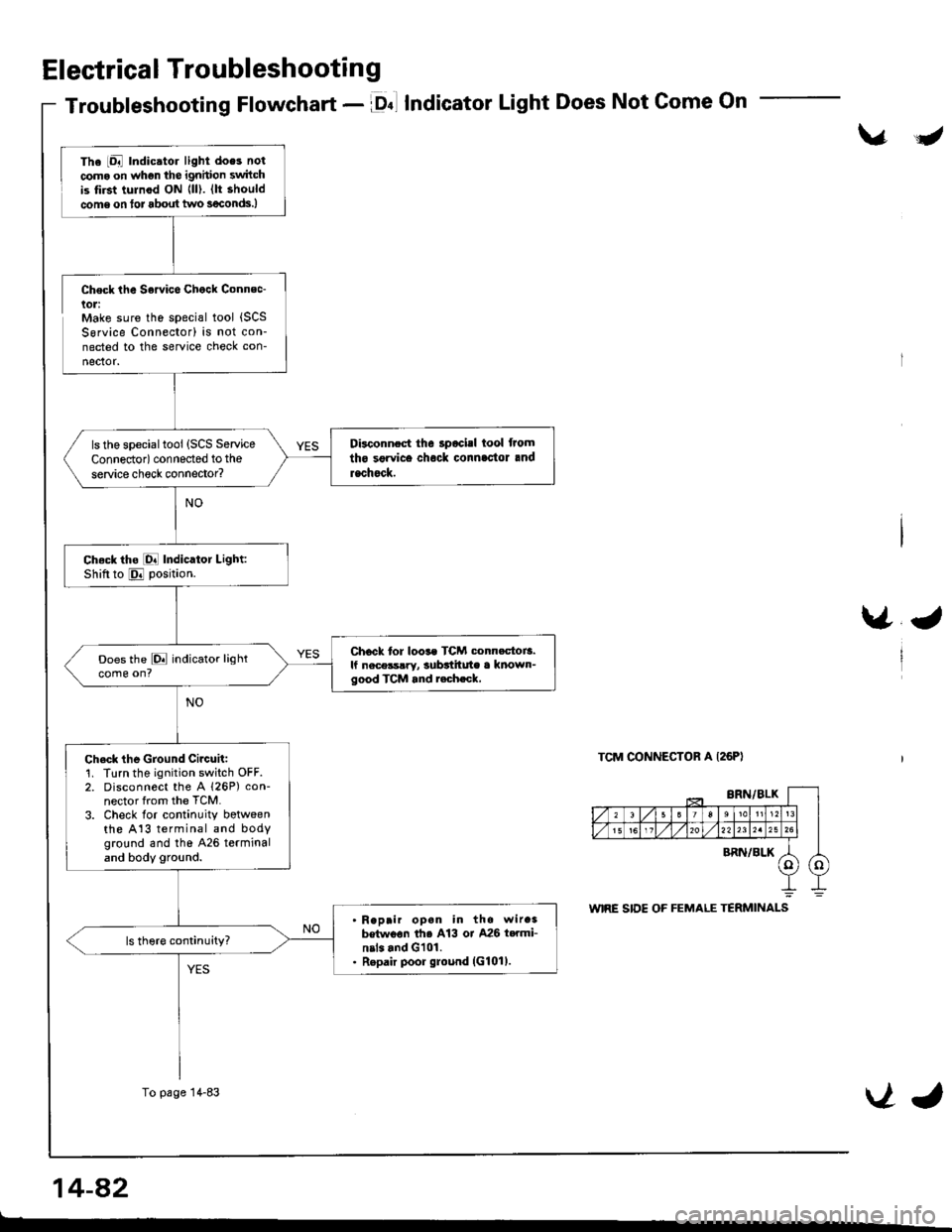
Electrical Troubleshooting
Troubleshooting Flowchart - lDnl IndicatorLight Does Not Come On
\/J
Check the Sowice Chock Connec-lol:Make sure the special tool {SCSSorvice Connector) is not con-nected to the service check con-
nector.
\/J
TCM CONNECTOR A I26PI
The iDal Indic.tor light does not
coma on whgn the ignhion switchis tirst tulnod ON {ll). (lt should
come on tor about two s€conds.)
Disconnect the 3pocisl tool from
tho sgrvice chock connlc'tor and
rachock.
ls the specialtool (SCS Service
Connedor) connected to the
service check connector?
Ch.ck tho [O! Indicator Light:Shiftto E position.
Chock tor loos. TCM conn.ctoi3.lf nece3s!ry, subttitute a known-good TCM and r.ch.ck,
Does the E indicator lightcome on?
Ch.ck the Ground Circuit:1. Turn the ignition switch OFF.2. Disconnect the A 126P) con-nector from the TCM.
3. Check lor continuity botweenthe A13 terminal and bodyground and tho 426 terminaland body ground.
Reprir opan in the wir.3betwoon th6 A13 or A26 t..mi-nil. and G101.Repair poor ground (G101).
To page 14-83VJ
14-a2
t-
Page 500 of 1681
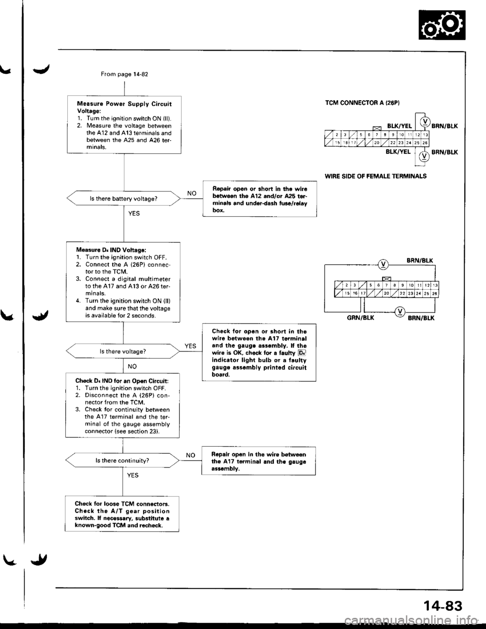
\.
\.
Measure Power Supply CircuitVoltage:1. Turn the ignition switch ON (ll).2. Measure the voltage betweenthe A12 and A13 terminals andbetween the A25 and 426 ter
Repeir open or short in tha wirebgtwoon th6 A12 .nd/or A25 tor-minrls and under-dash fu3e/r6layDox.
ls there battery voltage?
Measure O. IND Vohag.:1- Turn the ignition switch OFF.2. Connect the A (26P) connector to the TCIL3. Connect a digital multimeterto the A17 and A13 or 426 ter-minals.4. Turn the ignition switch ON (ll)
and make sure that the voltageis available for 2 seconds.
Check for open or short in thowire betweon the A17 torminaltnd the gauge as3emblv. ll thewire is OK, chock tor a faulty Eliindicator light bulb or a f.ultygauge assgmbly printgd circuitboard.Ch€ck D. IND for an Open Circuitr1. Turn the ignition switch OFF.2. Disconnect the A {26P} con,nector from the TCM.3. Check tor continuity betweenthe A17 terminal and the teFminal of the gauge assemblyconnector (see section 23).
Rap.ir open in tho wire betweenth. A17 tgrminal and the gsugeassembly.
ls there conlinuity?
Check lor loose TCM connectoB.Check the A/T goar positionswitch. lf necessary, substitute eknown-good TCM and.echock.
From page 14-82
TCM CONNECTOR A I26PI
BI-K/YELBRN/BLK
BLK/YELBRN/BLK
wlRE SIDE OF FEMALE TERMINALS
BRN/BLK
GRN/BLKBRN/BLK
14-83
Page 501 of 1681
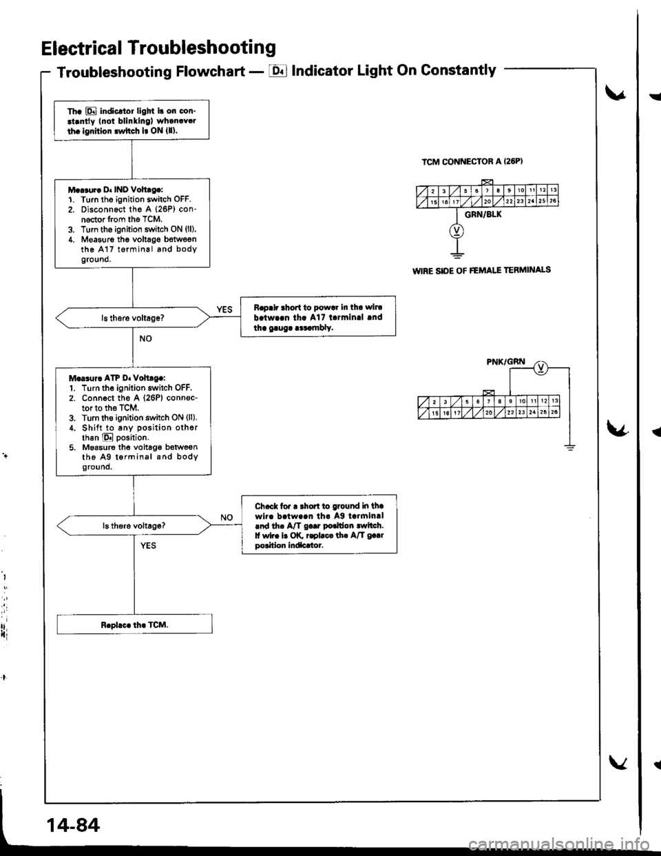
Electrical Troubleshooting
Troubleshooting Flowchart - EIndicator Light On Gonstantly
v
ICM CONNECTOR A I26PI
\4
I
i
rlIti
Th. E indicltor ligM i! on cor.
.t.ntly Inoi blinllng) wh.n.Y.l
th. lgrhior lwftch l. ON {ll).
M...ur. D. INO Vohtg.:1. Turn tho ignition switch OFF.
2. Disconnect th€ A (26P) con-noctor from the TCM.3. Turn the ignition switch ON (ll).
4. Measure thg voltag€ bstwegnthe A17 t6rminal and bodyground.
Rapalr ahort to powar In tha wiru
b.tw..n th. A17 l.rmin.l lnd
tha gaug. .cr.mbly.
M.a3ur. ATP D. voh.g.:1. Turn the ignition switch OFF.2. Conn€ct th€ A (26P) conn€c-tor to the TCM.3. Turn th€ ignition switch ON (ll).
4, Shift to any position otherthan E position.
5. Moasure the vohag€ b€tweenthe A9 tormin.l and bodyground.
Ch.ck tor r rhort to ground in thawir. b!tw..n th. Ag tarmin.l.nd th. A/T g..r potfion lwltch.f wi.e b OK r.pllca th. A/T g.|rpolition Indacrtor.
WIRE SIDE OF FEMAI.I TERMINALS
!
{
Page 507 of 1681
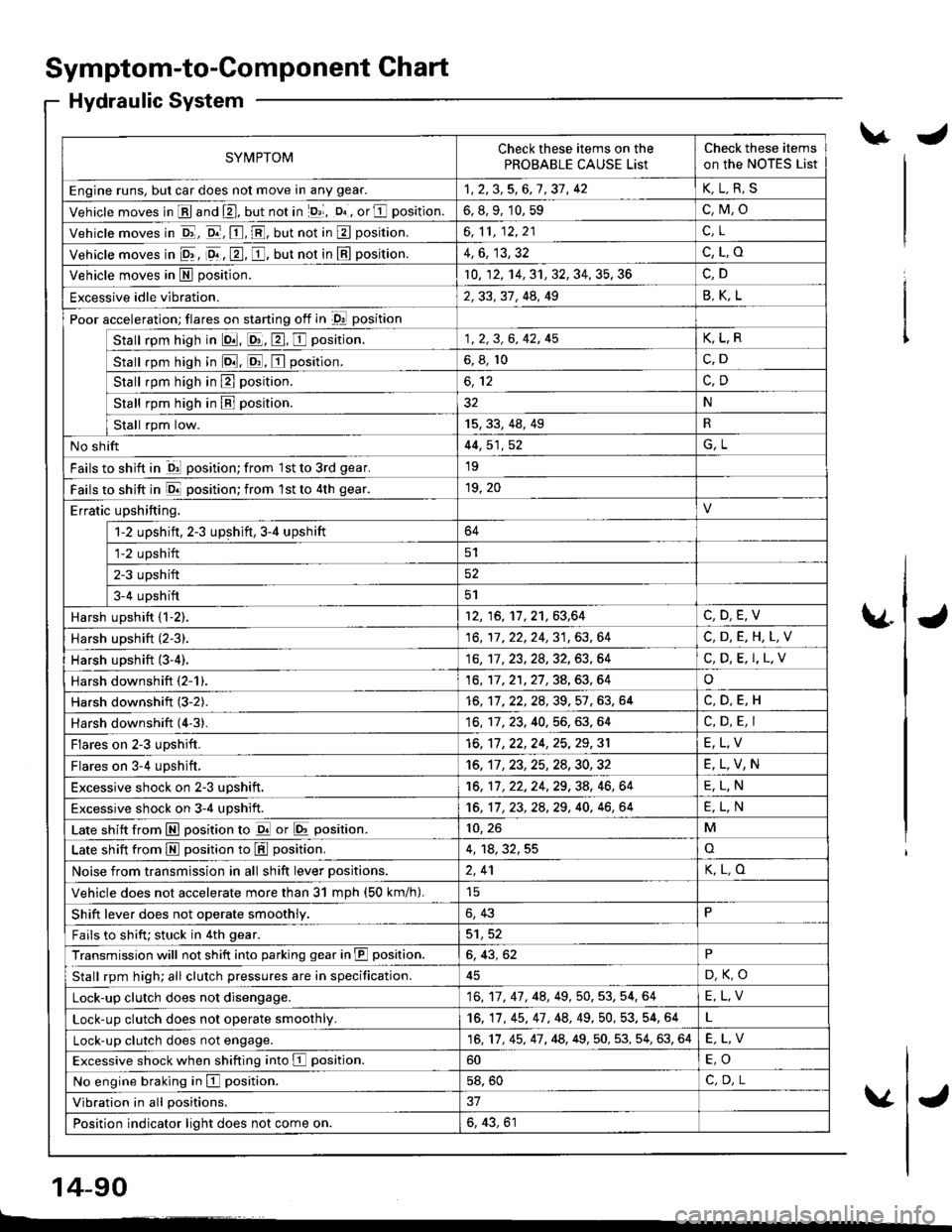
Symptom-to-Component Chart
Hydraulic System
SYMPTOMCheck these items on the
PROBABLE CAUSE List
Check these items
on the NoTES List
Engine runs, but car does not move in any gear.1,2,3,5,6,7,37, 42K,L.R,S
Vehicle moves in E and E, but not in lD,l, D. , or E position.6, 8, 9, 10, 59c,M,o
Vehicle moves in E, o.-, E, E, but not in E position.6,11,12,21c.L
Vehicle moves in 9r, 9. , E, E, but not in E position.4,6, 13,32c,L,o
Vehicle moves in E position.10, 12, 14, 31, 32, 34, 35, 36
Excessive idle vibration.2,33, 31, 44, 49B,K,L
Poor acceleration; flares on starting off in D! position
Stall rpm high in lQ|. E, E, E position.1, 2, 3, 6, 42, 45K,L,R
stall rpm high in lo.tl. ld, E position.6, 8, 10c.D
Stall rpm high in E position.
Stall rpm high in B position.32N
tat"tkp,ril"*'15,33,48,49R
No shift44, 51, 52G,L
Fails to shift in ql position; from 1st to 3rd gear.19
Fails to shift in E position; from lst to 4th gear.19, 20
Erratic upshifting.
1-2 upshift, 2-3 upshift,3-4 upshift64
fiz upshift
ETupshift52
Ia-+ upstrifi5l
Harsh upshift {1-2).12, 16, 11,21,63,64C,D,E,V
Harsh upshift (2-3).16,17,22,24,31,63,64C,D,E.H,L,V
Harsh upshift (3-4).16,'�tl. 23, 28, 32, 63, 64C, D, E. I,L.V
Harsh downshift (2-1).16, 17,21,27,34,63,64o
Harsh downshift (3-2).16, 11 ,22,2A,39,57 ,63, 64
Harsh downshift (4'3).16, 17, 23. 40, 56, 63. 64C, D, E, I
Flares on 2-3 upshift.16, 17 ,22,24, 25,29,31E,L,V
Flares on 3-4 upshift,16, 11 ,23,25,24,30,32E,L,V,N
Excessive shock on 2-3 uDshift.16, 11, 22, 24, 29, 38, 46, 64E,L.N
Excessive shock on 3-4 upshift.16, 11 , 23, 2a,29, 40, 46, 64E,L,N
Late shift from E position to d or E position.10, 26M
Late shift from M position to L!!l position.4, 18,32,55o
Noise from transmission in all shift lever Dositions.2,41K,L,O
Vehicle does not accelerate more than 31 mDh (50 km/h).
Shift lever does not operate smoothly.6, 43P
Fails to shifu stuck in 4th gear.5'1,52
Transmission will not shift into parking gear in JII position.6, 43, 62P
Stall rpm high; all clutch pressures are in specification.D,K,O
Lock-up clutch does not disengage.16,17, 47, 48,49, 50, 53, 54, 64E,L,V
Lock-up clutch does not operate smoothly.16, 17, 45, 47 , 48, 49,50, 53. 54, 64
Lock-up clutch does not engage.16,17, 45, 47, 48, 49,50, 53, 54, 63, 64E,L,V
Excessive shock when shifting into E position.60
No engine braking in E position.58, 50C,D.L
Vibration in all positions.
Position indicator light does not come on.6, 43, 61
\.J
\4J
v
14-90
L------�
J
Page 570 of 1681
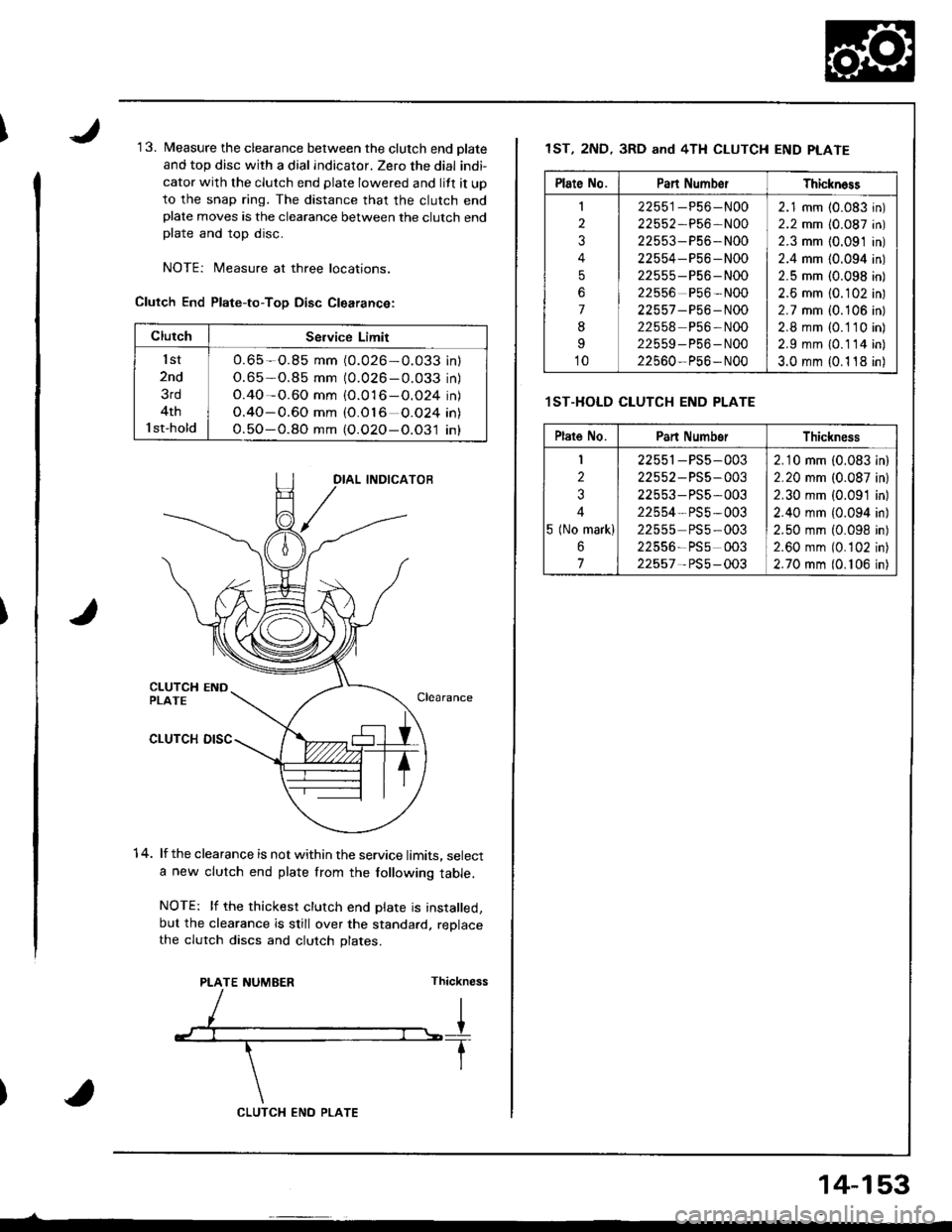
1 3. Measure the clearance between the clutch end olate
and top disc with a dial indicator. Zero the dial indi-
cator with the clutch end plate lowered and lift it up
to the snap ring. The distance that the clutch endplate moves is the clearance between the clutch endplate and top disc.
NOTEi Measure at three locations.
Clutch End Plate-to-ToD Disc Clearance:
1 4. lf the clearance is not within the service limits, selecta new clutch end plate from the following table.
NOTE: lf the thickest clutch end plate is installed,but the clearance is still over the standard. replacethe clutch discs and clutch plates.
PLATE NUMEERThickness
ClutchSeNice Limit
lst
2nd
3rd
4th
l st-hold
O.65 -O.85 mm (0.026-O.033 inl
O.65-0.85 mm (0.026 - 0.033 in)
O.40-0.60 mm {O.016-O.O24 in)
O.40-0.60 mm (O.O16 O.O24 in\
O.5O-O.8O mm (O.O2O-O.O31 in)
CLUTCX ENO PLATE
14-153
1ST, 2ND, 3RD and 4TH CLUTCH END PLATE
.lST.HOLD CLUTCH END PLATE
Plate No.Pan Numb€rThickn6ss
I
2
3
4
5
6
7
8
I
10
22551-P56-N00
22552,P56-N00
22553-P56-N00
22554-P56 -N00
22555 -P56- N00
22556 P56 -N00
22557 -P56 - N00
22558 P56-N00
22559-P56-N00
22560-P56- N00
2.1 mm (0.083 in)
2.2 mm (0.087 in)
2.3 mm {0.091 in)
2.4 mm (0.094 in)
2.5 mm (0.098 in)
2.6 mm {0.102 in)
2.7 mm i0.106 in)
2.8 mm (0. 1 10 in)
2.9 mm {0.114 in)
3.0 mm {0.1 18 in)
Plate No.Pan NumborThickness
I
2
3
4
5 (No mark)
6
7
22551-PS5-003
22552 - PS5-003
22553- PS5,003
22554- PS5 -003
22555 PS5-003
22556-PSs 003
22557- PS5-003
2.10 mm (0.083 in)
2.20 mm (0.087 inl
2.30 mm {0.091 in)
2.40 mm {0.094 in)
2.50 mm (0.098 in)
2.60 mm (0.102 in)
2.70 mm (0. 106 in)
Page 592 of 1681
Adiustment
CAUTION:
a All SRS wile harnesses are covered with yellow insu-
lation. Belore you disconnect any part ol an SRS wire
harness, disconnect the akbag connectors'
a Whenever the ignition switch is ON (ll), or has been
tumed OFF tol less than three minutes, be caletul not
to bump the SRS unit; the airbags could accidentally
deploy and cause damage or injuries'
a For additionalprecautions, referto the SRS sub-section
SBS MAIN HARNESS(Covered with yellow inslrlationl
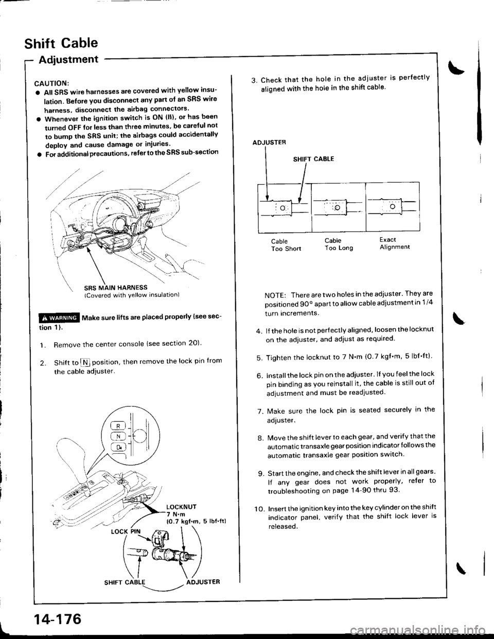
$!@ rtl"t . "ure lifts are placed plope y lsee sec-
tion 1 l.
'1. Remove the center console lsee section 20)'
2. Snitt to $ position, then remove the lock pin lrom
the cable adjuster'
LOCKNUT7 N.m10.7 kgf.m, 5 lbf.fl)
t
]H
@
@
@
{l
LOCK PIN
14-176
shift cable
3. Check that the hole in the adjuster is perfectly
sligned with the hole in the shift cable'
CableToo Short
NOTE: There are two holes in the adjuster. They are
positioned 9Oo apart to allow cable adiustment in 1/4
turn Incremenrs.
4. lJ the hole is not per{ectly aligned, loosen the locknut
on the adjuster, and adiust as required.
5. Tighten the locknut to 7 N'm (0.7 kgf'm, 5lbf'ftl
6. Installthe lock pin on the adiuster. lI you feelthe lock
pin binding as Vou reinstall it, the cable is still out ot
adjustment and must be readjusted.
7. [/ake sure the lock pin is seated securely in the
aoJusrer.
8. Move the shift lever to each gear, and verify that the
automatic transaxle gear position indicator follows the
automatic transaxle gear position swatch.
9. Start the engine, and check the shift lever in allgears'
lf any gear does not work properly, refer to
troubleshooting on page 14-90 thru 93.
10. Insert the ignition key into the key cylinder on the shift
indicator panel, verify that the shift lock lever is
released.
CableToo Long
ExactAlignment
\
ADJUSTER