air filter HONDA INTEGRA 1998 4.G Workshop Manual
[x] Cancel search | Manufacturer: HONDA, Model Year: 1998, Model line: INTEGRA, Model: HONDA INTEGRA 1998 4.GPages: 1681, PDF Size: 54.22 MB
Page 217 of 1681
![HONDA INTEGRA 1998 4.G Workshop Manual System Description
Vacuum Connections (contdl
Bl8Cl engine:
rl
llj
lli;r
Fil
ryl
xr
flti
li
tl
I
lr; I
,l{9^h;L-r
-1] PRIMARY HEATED OXYGEN SENSOR IPRIMARY HO2SItsENsoR 1l
O SECONDARY HEATED OXYGE HONDA INTEGRA 1998 4.G Workshop Manual System Description
Vacuum Connections (contdl
Bl8Cl engine:
rl
llj
lli;r
Fil
ryl
xr
flti
li
tl
I
lr; I
,l{9^h;L-r
-1] PRIMARY HEATED OXYGEN SENSOR IPRIMARY HO2SItsENsoR 1l
O SECONDARY HEATED OXYGE](/img/13/6069/w960_6069-216.png)
System Description
Vacuum Connections (cont'dl
Bl8Cl engine:
rl
llj
lli;r
Fil
ryl
xr
flti
li
tl
I
lr; I
,l'{9^h;'L-r
'-1] PRIMARY HEATED OXYGEN SENSOR IPRIMARY HO2SItsENsoR 1l
O SECONDARY HEATED OXYGEN SENSOR (SECONDARY
HO2SI ISENSOR 2)
.3) MANIFOLD ABSOLUTE PRESSUBE {MAPI SENSORii ENGINE COOLANT TEMPERATURE (ECT} SENSORii INTAKE AIR TEMPERATURE IIAT) SENSORi6-- CRANKSHAFT SPEEO FLUCTUATION ICKF} SENSOR
a7) KNocK sENsoR lKslO IDLE AIR CONTROL IIAC) VALVE
i' FUEL INJECTOR
@ FUEL FILTER
O FUEL PRESSURE REGULATOR
[4 FUEL PUMP {FP}@ FUEL TANKI.13 FUEL TANK EVAPORATIVE EMISSION (EVAP) VALVE
.19 FUEL PULSATION DAMPER{!9 AIR CLEANER
O RESONATOR
I t-az
I: Vacuum hose No.
iio INTAKE AIR BYPASS IIAE) CONTROL DIAPHRAGM VALVE(!9) INTAKE AIR BYPASS {IABI CONTROL SOLENOID VALVE
6I INTAKE AIR BYPASS (IAB) VACUUM TANK
CI INTAKE AIR BYPASS {IABI CHECK VALVE
€9 THREE WAY CATALYTIC CONVEFTER (TWC)
2jI POSITIVE CRANKCASE VENTILATION (PCV} VALVE
€! EVAPORATIVE EMISSION (EVAPI CONTROL CANISTER
?9 EVAPORATIVE EMISSION {€VAPI PURGE CONTNOLSOLENOID VALVE0d EVAPORATIVE EMISSION (EVAP}TWO WAY VALVE
iii) EVAPORANVE EMISSION {EVAP) BYPASS SOLENOID VALVE,3 EVAPORAIVE EMTSSTON {EVAP} CONTROL CANISTER VENTSHUT VALVE?9 FUEL TANK PRESSUR€ SENSORi3O] EVAPORATIVE EMISSION IEVAP} THREE WAY VALVE
Page 218 of 1681
![HONDA INTEGRA 1998 4.G Workshop Manual 818C5 engine:
il] PRIMARY HEATED OXYGEN SENSOR {PRIMARY HO2SI{SENSOR 1)O SECONDARY HEATED OXYGEN SENSOR ISECONDARYHO2S) {SENSOR 2)O MANIFoLD ABSoLUTE PFESSURE (MAPI sENsoRi4] ENGINE COOLANT TEMPERATUR HONDA INTEGRA 1998 4.G Workshop Manual 818C5 engine:
il] PRIMARY HEATED OXYGEN SENSOR {PRIMARY HO2SI{SENSOR 1)O SECONDARY HEATED OXYGEN SENSOR ISECONDARYHO2S) {SENSOR 2)O MANIFoLD ABSoLUTE PFESSURE (MAPI sENsoRi4] ENGINE COOLANT TEMPERATUR](/img/13/6069/w960_6069-217.png)
818C5 engine:
il] PRIMARY HEATED OXYGEN SENSOR {PRIMARY HO2SI{SENSOR 1)O SECONDARY HEATED OXYGEN SENSOR ISECONDARYHO2S) {SENSOR 2)O MANIFoLD ABSoLUTE PFESSURE (MAPI sENsoRi4] ENGINE COOLANT TEMPERATURE {ECT} SENSOR(9) INTAKE AIR TEMPERATURE IIAT} SENSORG) CRANKSHAFT SPEED FLUCTUATTON TCKFI SENSON[t KNOCK SENSOR tKSt@ IDLE AIR coNTRoL {IACI vALvEO FUEL INJECToR{D FUEL FILTERO FUEL PRESSURE REGULAToR(} FUEL PUMP {FP}(} FU€L TANK
FUEL TANK EVAPORATIVE EMISSION (EVAPI VALVEFUEL PULSATION DAMPERAIR CLEANERRESONATORTHREE WAY CATALYTIC CONVERTER {TWCIPOSITIVE CRANKCASE VENNLATION (PCV) VALVEEVAPOMTIVE EMISSION {EVAP} CONTNOL CANISTEREVAPONATIVE EMISSION {EVAP) PURGE CONTROLSOLENOID VALVEEVAPORATIVE EMISSION IEVAP} TWO WAY VALVEEVAPORATIVE EMISSION IEVAP) BYPASS SOLENOID VALVEEVAPORATIVE EMISSION IEVAP) CONTROL CANISTER VENTSHUT VALVEFUEL TANK PRESSURE SENSOREVAPORATIVE EMISSION IEVAP}THREE WAY VALVE
@4a\
(D
o(D
G)@
@@@
.@
@
11-13
Page 281 of 1681

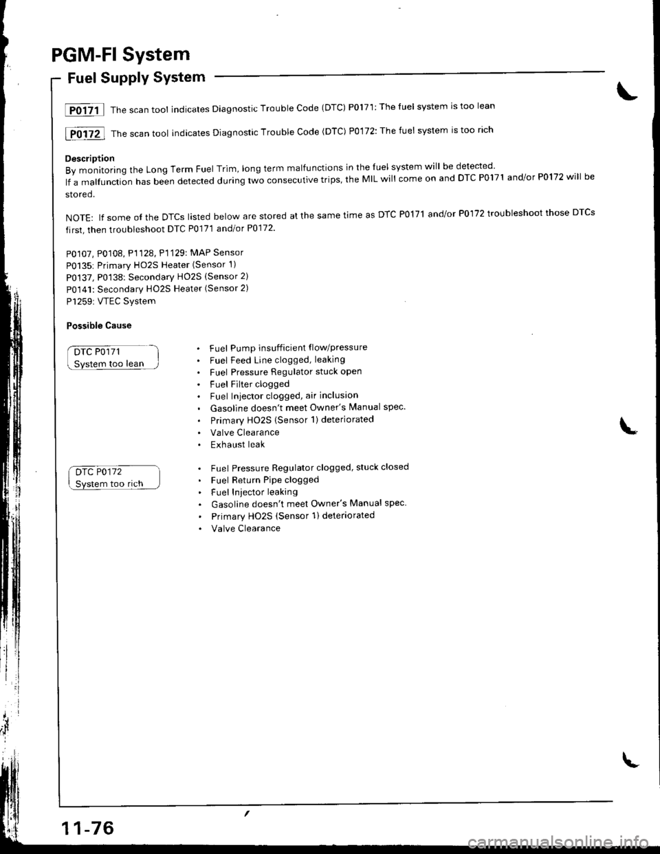
PGM-Fl System
Fuel Supply System
lF0{7il Thescantool indicates Diagnostic Trouble Code (DTC) P0171:Theluel system rstoo lean
[F0i72l Th" ""un tool indicates Diagnosric Trouble code (DTc) p0,172: The fuet system is too rich
Description
By monitoring the Long Term Fuel Trim, long term malfunctions in the luel system will be detected
lf a malfunction has been detected during two consecutive trips, the MIL will come on and DTC P0171 and/or P0172 will be
stored.
NOTE: lf some ol the DTCS lasted below are stored at the same time as DTC PolTl and/or P0172 troubleshoot those DTCS
first, then troubleshoot DTC P0171 andlot P0172
PO107, P0108, P1128. P1129: MAP Sensor
P0135: Primary HO2S Heater (Sensor 1)
P0137, P0138: Secondarv HO2S (Sensor 2)
P0141: Secondary HO2S Heater (Sensor 2)
P1259: VTEC Svstem
Possible Cause
DTC P0171
too lean
Drc P0172
Svstem too rich
. Fuel Pump insufficient flowpressure
. Fuel Feed Line clogged, leaking
. Fuel Pressure Regulator stuck open
. Fuel Filter clogged. Fuel Iniector clogged, air inclusion
. Gasoline doesn't meet Owner's Manual spec.
. Primary HO2S (Sensor 1)deteriorated
. Valve Clearance. Exhaust leak
. Fuel Pressure Regulator clogged, stuck closed
. Fuel Return Pipe clogged
. Fuel Iniector leaking
. Gasoline doesn't meet Owner's Manual spec
' Primary Ho2s (Sensor 1) deteriorated
. Valve Clearance
Page 545 of 1681

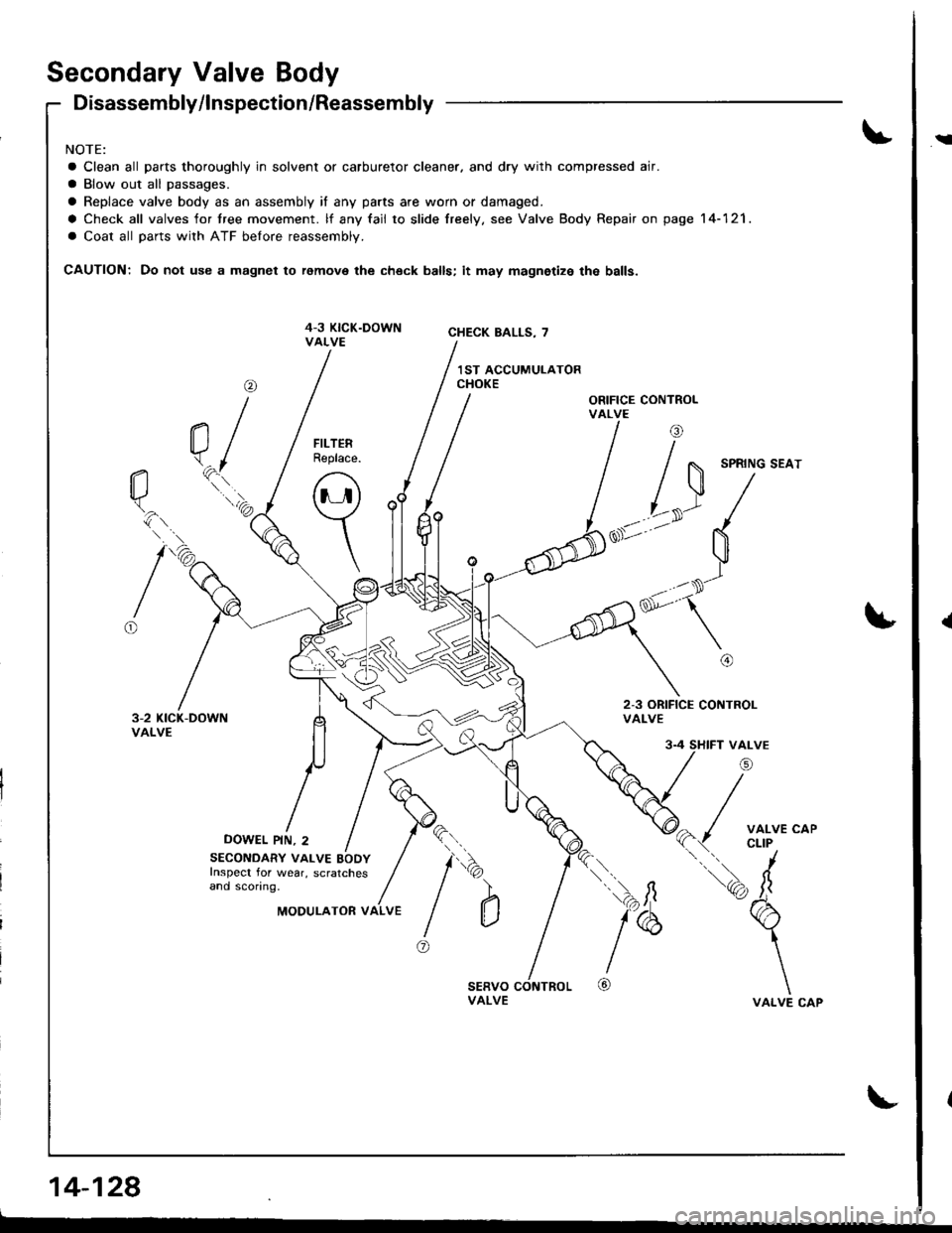
Secondary Valve Body
Disassembly/lnspection/Reassembly
NOTE:
a Clean all parts thoroughly in solvent or carburetor cleaner. and dry with compressed air.
a Blow out all passages.
a Replace valve body as an assembly if any parts are worn or damaged.
a Check all valves for tree movement. lf any fail to slide freely. see Valve Body Repair on page 14-121.
a Coat all parts with ATF belore reassembly.
CAUTION: Do not use a magnet to remove the check balls; it may magnetize the balls.
ORIFICE CONTROLVALVE
2-3 ORIFICE CONTROLVALVE
DOWEL PIN, 2
@
a/\.^fl*..'a
tio.
16
FILTERReplace.
o
\
SECONDARY VALVE BODYInspect for wear, scratchesand sconng.
4 SHIFT VALVE
/i
( / ;fl'J'*'
tq, fr
b
\
\VALVE CAP
l"
@
\
)
@
da')
aMODULATOR VALVE
14-128
i
{
Page 589 of 1681
![HONDA INTEGRA 1998 4.G Workshop Manual 17. Make sure the transmission is in E] position.
Fill the transmission with ATF, and run the engineJor 30 seconds or until approximately one quart isdischarged.
18. Remove the drain hose, and reconn HONDA INTEGRA 1998 4.G Workshop Manual 17. Make sure the transmission is in E] position.
Fill the transmission with ATF, and run the engineJor 30 seconds or until approximately one quart isdischarged.
18. Remove the drain hose, and reconn](/img/13/6069/w960_6069-588.png)
17. Make sure the transmission is in E] position.
Fill the transmission with ATF, and run the engineJor 30 seconds or until approximately one quart isdischarged.
'18. Remove the drain hose, and reconnect the coolerreturn hose to the transmission.
19. Refillthe tiansmission with ATF to the propef level.
FILLER CAP
TOOL MAINTENANCE
1. Empty and rinse after each use. Fill the can withwater and pressurize the can. Flush the dischargeline to ensure that the unit is clean.
2. lf discharge liquid does not foam, the orifice may beblocked.
3, To clean, disconnect the plumbing from the tank atthe large coupling nut,
4. Remove the in-line filter trom the discharge side andclean if necessary.
5. The fluid oritice is located behind the filter.
Clean it with the pick stored in the bottom of the tankhandle or blow it clean with air. Securely reassem-
ble all parts.
COUPLING NUT
FILTER
\
IO-RINGORIFICE
14-173