service indicator HONDA INTEGRA 1998 4.G Owner's Manual
[x] Cancel search | Manufacturer: HONDA, Model Year: 1998, Model line: INTEGRA, Model: HONDA INTEGRA 1998 4.GPages: 1681, PDF Size: 54.22 MB
Page 1124 of 1681
Battery
a Battery fluid (electrolytel contains sulfuric acid. lt may causo severe burns if it gsts on yout skin or in your eyes.Wear piotective clothing and a face shield.- ll electrolyte gets on your skin or clothes, rinse it ofl with water immediately.- lf electlolyte gets in your eyes, tlush it out by splashing water in your eyes for at least 15 minutes; call a physicianimmediately.
a A battery gives off hydlogen gas. lf ignited, the hydrogen will explode and could crack the battery case and splatte.acid on you. K6ep sparks, flames, and cigarettes away from the battery.a Overchalging will raisc the temperatulg of the electrolyte. This may force electrolyte to spray out ol the battery vents.Follow the chatge. manutacturer's instructions and charge the baftely at a ptope. rate.
NOTE: The original radio has a coded theft protection circuit. lf service to the car requires any of the tollowing, be sureto get the customer's code number before- disconnecting the battery.- removing No. 47 (7.5 A) fuse from the under-hood fuse/relay box.- removing the radio.
After service, reconnect power to the radio and turn it on. When the word "CODE" is displayed, enter tne customer's5-digit code to restore radio operation,
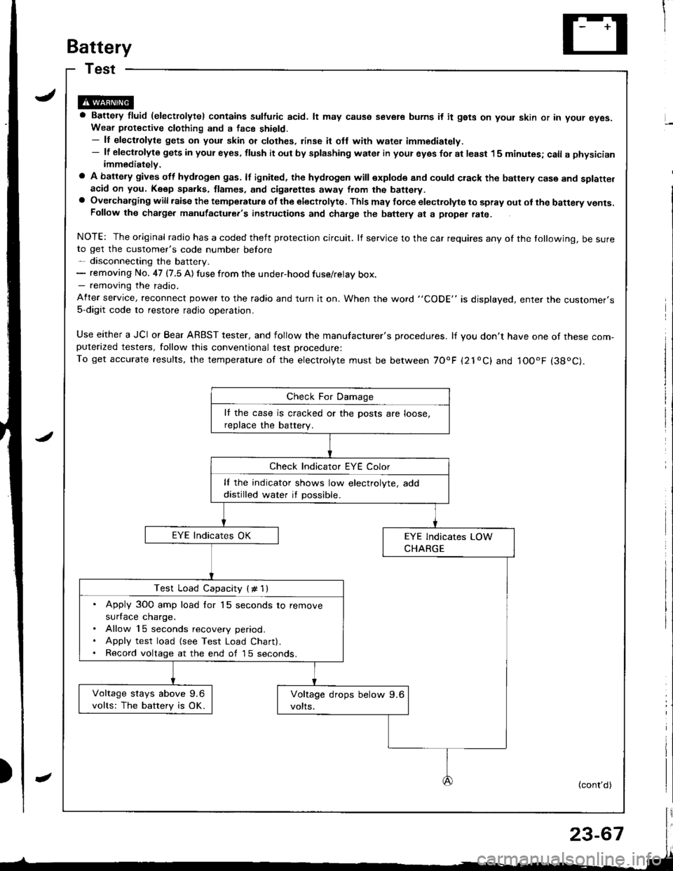
Use either a JCI or Bear ARBST tester, and follow the manufacturer's procedures. lf you don't have one of these com-puterazed testers, follow this conventional test Drocedure:To get accurate results, the temperature of the electrolyte must be between 70'F {21oC} and IOOoF (38oC).
lf the case is cracked or the posts are loose,
reDlace the batterv.
lf the indicator shows low electrolyte, add
distilled water if possible.
Test Load Capacity (# 1l
. Apply 3O0 amp load for 15 seconds to remove
surface charge.. Allow 15 seconds recovery period.. Apply test load {see Test Load Chart).. Record voltage at the end of l5 seconds.
Voltage stays above 9.6
volts: The battery is OK.
(cont'd)
Page 1332 of 1681
!
Gomponent/Wiring Locations Index
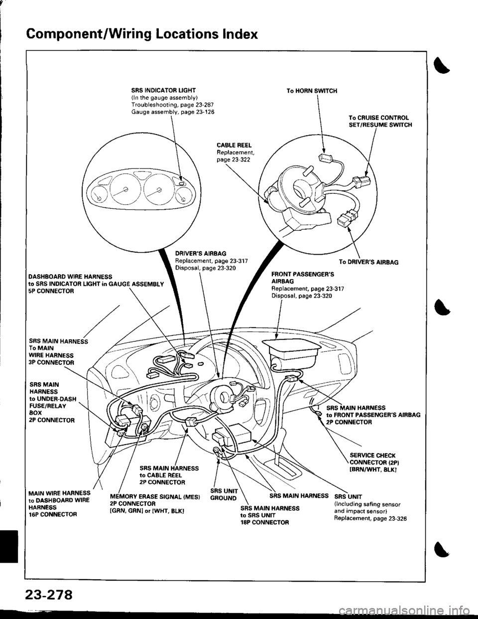
SRS INDICATOR LIGHT(ln the gauge assembly)Troubleshooting, page 23-287Gauge assembly, page 23-126
To HORN SWITCH
CABLE REELReplacement,page 23-322
DRIVER'S AIRBAGReplacement. page 23-317Disposal, page 23-320To DRIVER'S AIRBAG
DASHBOARD WIRE HARNESSFRONT PASSENGER'SAIRBAGBeplacement, page 23-317Disposal, page 23-320
to SRS INDICATOR LIGHT in GAUGE ASSEMBLY5P CONNECTOR
SRS MAIN HARNESSTo MAINWIRE HARNESS3P CONNECTOR
SRS MAINHARNESSto UNDER-DASHFUSE/RELAYBOX2P CONNECTOR
HARNESSto FRONT PASSENGERS AIRBAG2P CONNECTOR
SRS MAIN
SERVICE CHECXCONNECTOR {2PIIBRNAAIHT, BLK]to CABLE REEL2P CONNECTOR
MAIN WIRE HARNESSto DASHBOARD WIREHARNESS16P CONNECTOR
ERASE SIGNAL (MES}SRS UNITGBOUNOSRS MAIN HARNESSSRS UNIT(lncluding safing sensorano rmpact sensor)R6placement, page 23-326
2P CONNECTORSRS MAIN HARNESSto SRS UNIT18P CONNECTOR
S\--0
[GRN, GRNI or IWHT, BLKI
23-27A
Page 1333 of 1681
Description
I
J)
)
'\' '\, ili \.-.-1 i^\\,,; i \
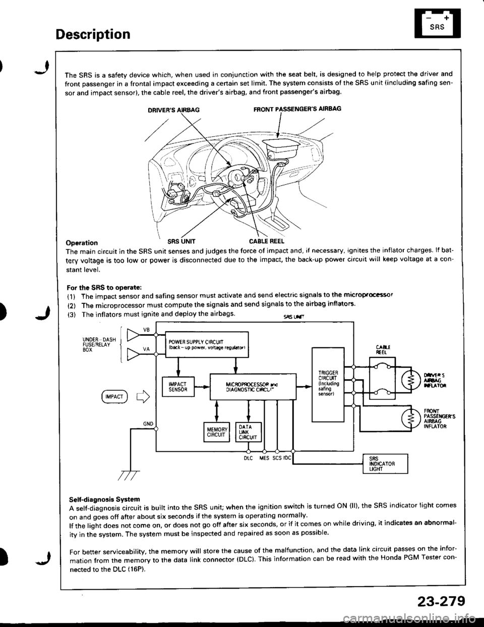
The SRS is a safetv device which, when used in coniunction with the seat belt, is designed to help protect the driver and
front passenger in a frontal impact exceeding a cenain set limit. The system consists ot the SRS unit (including safing sen-
sor and imDact sensor), the cable reel, the driver's airbag, and front passenger's airbag
Operation t'Its
The main circuit in the SRS unit senses and judges the force ot impact and, il necessary, ignites the inflator charges. If bat-
tery voltage is too low or power is disconnected due to the impact, the back-up power circuii will keep voltage at a con-
stant level.
For the SRS to operate:
(1) The impact sensor and safing sensor must activate and send electric signals to lhe mictop.Goi
{2) The microprocessor must compute the signals and send signals to the airbag inflators'
(3) The inflators must ignite and deploy the airbags sE Lr.r
UNDER DASHFUSE/RELAYBOX
Dnftr sAtacranroq
IIMPACT I ] )
F80t{TPASSEI{GEffSAIRSAGINFLAIOR
Drc MES SCS rDC
Self-diagnosis System
A self-diagnosis circuit is built into the sRs unit; when the ignition switch is turned oN (ll), the sRS indicator light comes
on and goes off after about six seconds if the system is operating normally'
lf the light does not come on, or does not go off after six seconds, or if it comes on while driving. it indicates an abnormal-
ity in the system. The system must be inspected and repaired as soon as possible'
For better servicesbility. the memory will store the cause of the malfunction, and the data link circuit passes on the infor-
mation from the memory to the data link connector (DLC). This information can be read with the Honda PGM Tester con-
nected to the DLc (16P).
23-279
J
Page 1334 of 1681
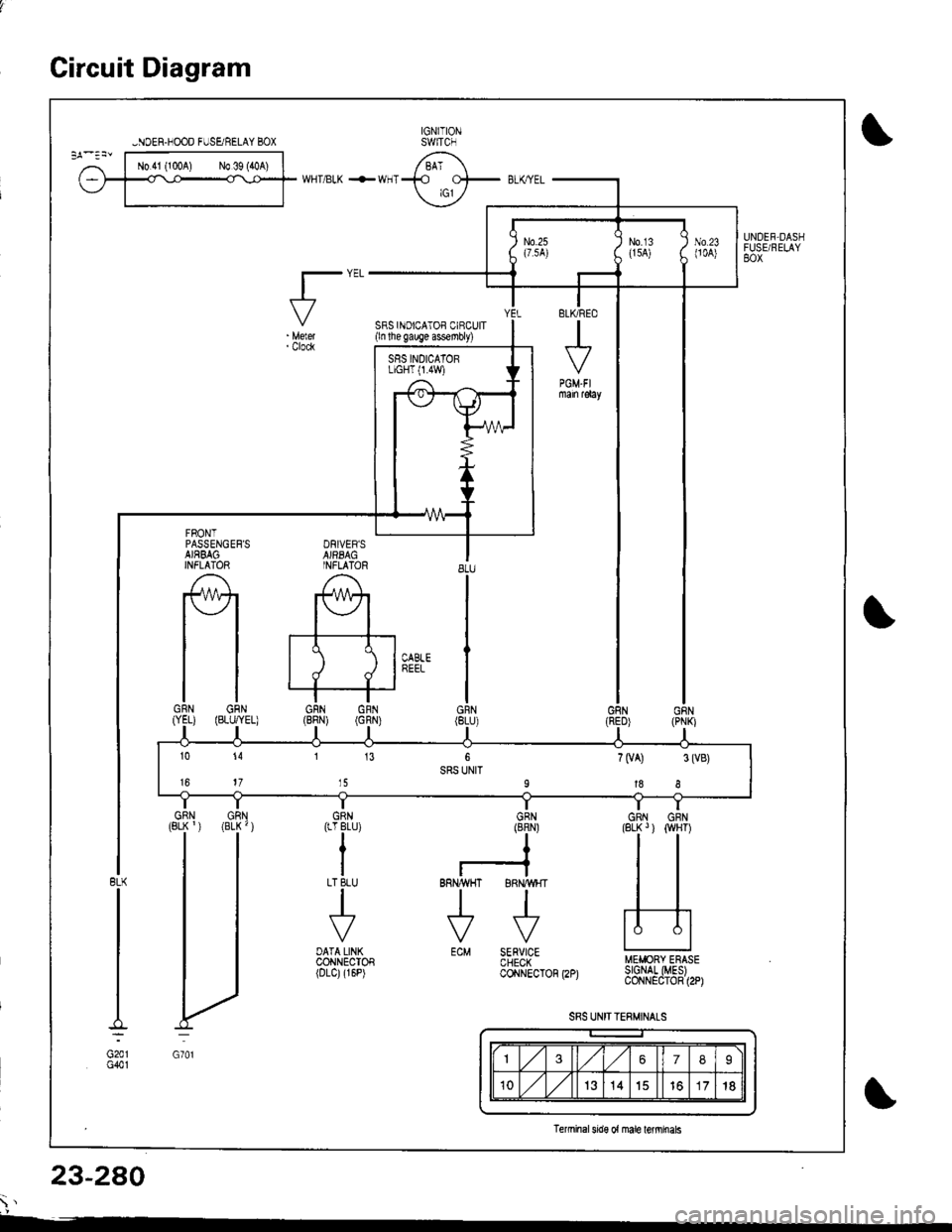
Circuit Diagram
FRONTPASSENGEF'SAJRBAGINFLATOR
f\4r
tlGRN GRN(YEL) (BLi.,'YEL)
I
G701
IGNITIONswtTcH
SRS INOICATOF CIBCUIT(ln the gauge assembly)
8LU
I
I
siEi'
IGRN
GRN(8RN)
I?
RNAVHT BRII/WHTlltl\---7 \*7
ECM SERVICECHECKcoirNEcTon
WHT/BLK +WHT
t"'
DATA LINKCONNECTOF(DLC)(r6P)
UNDEF-DASHFUSURELAY80x
ELKRED
J
PGM-FImain r€lay
MEIiIORY ERASEr2pt SIGNAL (MESIcoNNECToR (2P)
SRS UNIT TERMJNALS
BLX
G201G401
-NOER.NOOD FUSE/RELAY BOX
SRS INDICATORLIGHT 0.4W)
10 14 1 13 6 7(VA) 3(VB)SRS UNIT16 17 15 9188
DRIVER'SAJFBAGINFLATOR
1367I
10,/1,/1314151718
lerminal sde o{ male tefinnals
23-280
\'
Page 1341 of 1681
)
Troubleshooting
Self-diagnostic Procedures
The self-diagnostic function of the SRS system allows it to locate the causes of system problems and to store this informa-
tion in memorv. For easier troubleshooting, this data can be retrieved via 8 dats link circuit.
o When you turn the ignition switch ON (ll), the SRS indicator will come on. lf it goes off after six seconds, the system is
normat.
. lf there is 8n abnormality, the system locstes and defines the problem, stores this information in memory, and turns
th€ SRS indicator light on. The data will remain In the memory even when the ignition switch is turned off or if the bat-
terv is disconnected.
. When you connect the SCS service connector to the service check connector (2P), and turn the ignition switch ON {ll),
the sRs indicator light will indicate the diagnostic trouble code (DTCI by th€ number of blinks.
. After reading and recording the DTC, proceed with the troubleshooting for this code
Pr6crution!
. Use only a digital multimeter to check the system, lf it's not a Honda multimeter, make sure its output is 10 mA (0.01 A)
or less when switched to the smallest value in the ohmmeter range. A tester with a higher output could damsge the
airbag circuit or cause sccidental airbag deployment and possible injury.
. Whenever the ignition switch is ON (ll), or has been turned OFF for less than three
SRS unit; the airbags could accidentally deploy and cause damage or injuries'
. Before you remove the SRS main harness, disconnect the driver's airbag connector
conneclor.
and the front passenger's airbag
. Make sure the battery is sufficiently charged (s6e psge 23-67). lf the battsry is dead or low, msasuring values won't be
correct,
a Do not touch a tester probe to the terminals in the SRS unit or harness connectors, and do not connect the terminals
with a jumper wire. Use only the backprobe set and the SCS service connector.
For backprobing spring-loaded lock type connectors, refer to psge 23-283.
Reading the DTC
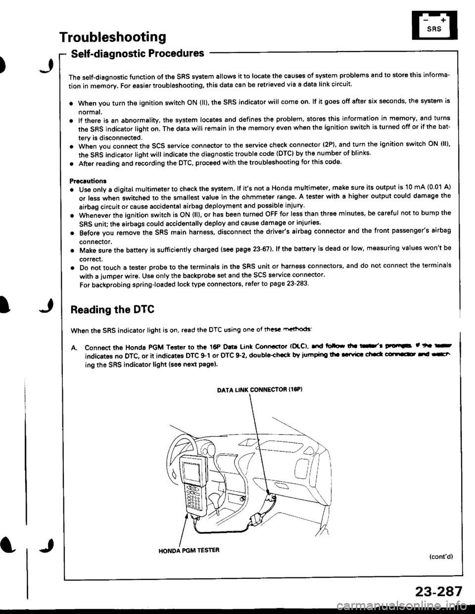
When the SRS indicator light is on, read the DTC using one ot th"sc rn"ihod<
A. Connect the Honda PGM Toster io the 16P D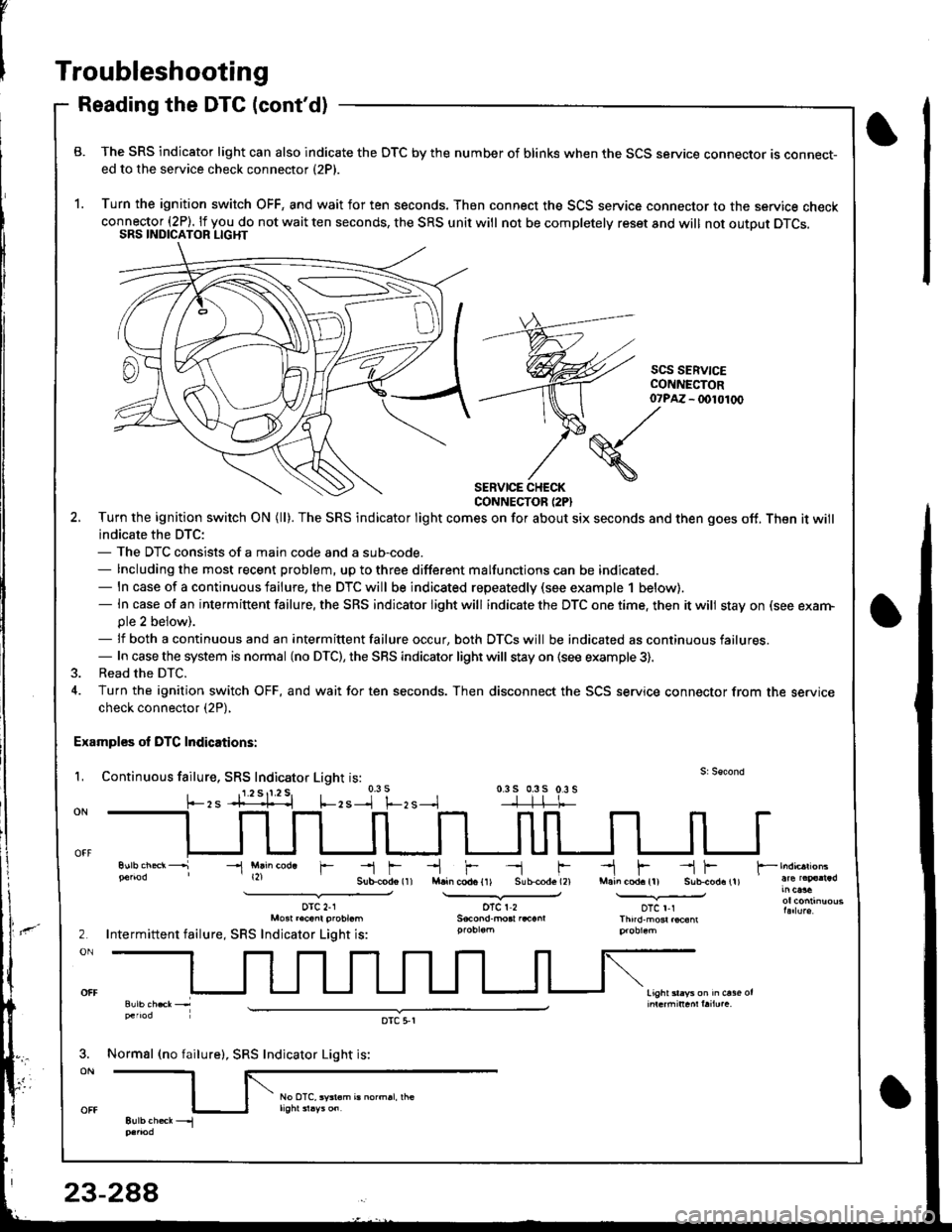
v
-t f--.l r --1 f-M.in cod. {11 S!b{od. (2}
oTcr2
-l F --{ FMain cod. (l) Sub-cod.11).--.Y-oTc r-rThnd'm6r.@6m
2
ON
light sl.ys on h ct36 or
Troubleshooting
Reading the DTC (cont'd)
B. The SRS indicator light can also indicate the OTC by the number of blinks when the SCS service connector ts connect-ed to the service check connector (2P).
1. Turn the ignition switch OFF, and wait for ten seconds. Then connect the SCS service connector to the service checkconnector (2P). lf you do not wait ten seconds, the SRS unit will not be completelv reset and will not outout DTCS.SRS INDICATOR LIGHT
scs SERV|CECONI{ECTOR- (x)l01(x)
SERVICE CHECKCONNECTOR (2PI
2. Turn the ignition swilch ON (ll). The SRS indicator light comes on for about six seconds and then goes off. Then it will
indicate the DTC:- The DTC consists of a main code and a sub-code.- Including the most recent problem, up to three different malfunctions can be indicated.- ln case of a continuous failure, the DTC will be indicated repeatedly (see example 1 below).- In case of an intermiftent failure, the SRS indicator light will indicate the DTC one time. then it will stay on (see exarn-ple 2 beiow).- lf both a continuous and an intermittent failure occur, both DTCS will be indicated as continuous failures.- In case the system is normal (no DTC), the SRS indicator light will stay on {see example 3).
3. Read the DTC.
4. Turn the ignition switch OFF, and wait for ten seconds. Then disconnect the SCS service connector from the servicecheck connector (2P),
Examples ol DTC Indications:
L Continuous failure, SRS Indicator Light is:0.3 s 0.3s 0.3 s-]-]-l-t-
07?M
(S./'
\
-l Mlin cod. r
orc 2-1Mo3t r.cant probt.m
Intermittent failure, SRS Indicator Light is:
Normsl (no failure), SRS Indicator Light is:
oTc 5,r
Page 1343 of 1681
)
Erasing the DTC Memory
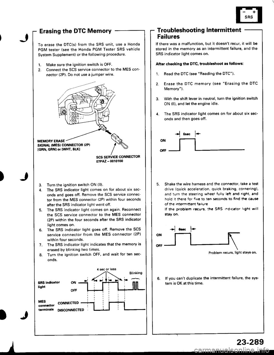
To erase the DTC(S) from the SRS unit, use a Honda
PGM tester (see the Honda PGM Tester SRS vehicle
System Supplement) or the following procedure.
1. Make sure the ignition switch is OFF.
2. Connect the SCS service connector to the MES con-
nector (2P). Do not use a jumper wlre.
MEMORY EMSESIGNAL {MESI CONNESTOR I2P)
[GRN, GBNI or IWHT, BLKI
Turn the ignition switch ON (ll).
The SBS indicator light comes on for about six sec-
onds and goes off. Remove the SCS service connec-
tor from the MES connector (2P) within four seconds
after the SRS indicator light went off.
The SRS indicator light comes on again. Reconnect
the scs service connector to the MES connector
(2P) within the four seconds after the SRS indicator
light comes on.
The SRS indicator light goes off. Remove the SCS
service connector from the MES connector (2P)
within four seconds.
The SRS indicator light indicates that the memory is
erased by blinking two times.
Turn the ignition switch OFF. and wait for ten sec-
onos.
Troubleshootin g Intermittent
Failures
lf the.e was a malfunction, but it doesn't recur, it will be
stored in the memory as an intermittent failure, and the
SRS indicator light comes on,
Atter chocking ths DTC, troubleshoot as follows:
1. Read the DTC (see "Reading the DTC").
2. Erase the DTC memory (see "Erasing the DTC
Memory").
3. With the shift l€ver in neutral, turn the ignition switch
ON (ll), and let the engine idle.
4. The SRS indicator light comes on for about six sec-
onds and then goes off.
I o"* 1--
ONllI
Shake the wire harness and the connector, take a test
drive (quick acceleration, quick braking, cornering),
and turn the steering wheel fully left and righi, and
hold I there for fve to ten s€conds lo 6nd tt|e caus€
of the intermnem farlure
It lhe problem .!curs, lha SRS nd'calor r'ghl will
$aY on.
,l soc or less
Problem recurs, Iight stays on
lf vou can't duplicate the intermittent failure, the sys-
tem is OK at this time.SRS indic.lollight
MESconnaclottarrninlll
CONNECTED
DISCONNECTED
23-289
Page 1355 of 1681
)
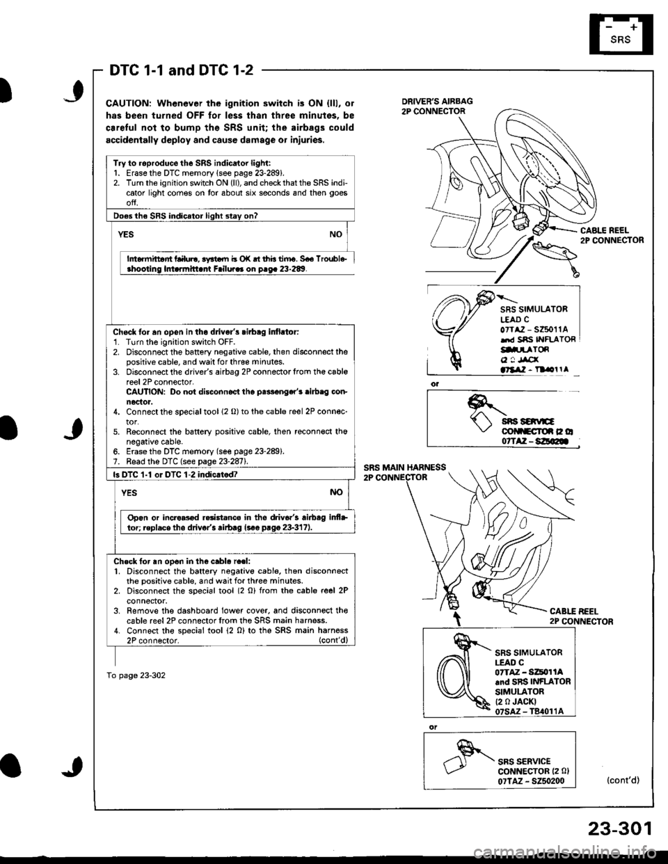
DTC 1-1 and DTC 1-2
CAUTION: Whenever the ignition switch is ON {lll, or
has been turned OFF for less thsn three minutes, be
ca.eful not to bump the SRS unit; the airbags could
accidentally deploy and cause damage or iniuries.
CABLE REEL2P CONNECTOR
SRS SIMULATORL€AD CoTtaz - s6011Alrd Sns IYFLATORg.prToR
o ! Jrcxatllil - n olrl
*.t sns savE\,' colltcroe c o07TAZ-8E@
CABLE BEEL2P CONNECTOR
SRS SERVICEGoNNECTOR (2 0l
07TAZ - 5250200(cont'd)
Try to roproduce the SRS indicator light:1. Erase the DTC memory lsee page 23-289).2. Turn the ignition switch ON (ll), and check that the SRS indicator light comes on tor about six seconds and then goes
ofJ.
Do€s the SRS indicator light stay on?
YES
h6rmittar'rt Lalul!, 3yrtdll b o|( rt thb tiiru. 5€6 lroubl6-ahootino lmarmitlant Failura. on o.oa 23-289.
Chock fo. an opGn in the dlivgl's cirbag infirtor:'1. Turn the ignition switch OFF.2. Disconnect the battery negative cable, then disconnect thepositive cable, and wail for thrce minutes.3. Disconnect the driver's airbag 2P connectorlrom th€ cablereel 2P connector-CAUTION: Do not disconnoct tho palF€nger'r .ilb.g con-nector.4. Connect the sDecial tool 12 o) to the cable reel 2P connec-tor.5. Reconnect the bsftery positive cable, then reconn€ct thonegative cable.6. Erase the DTC memory (se€ page 23-289).7. Bead the DTC (see page 23-2811.
ls DTC 1-1 oI DTC 1-2 indic.tod?
YESNO
Opon or incro8od r.rist.nco in tho driv6.'3 airbag inf+
lor; replacs tho drivor'3 rirb.g lsoe prgg 23-317).
Ch.ck for an op6n in the cablo re.l:1. Disconnect the battery negativo cabl6, thon disconnectthe positive cable, and wait for three minutes.2. Disconnect the soecial tool (2 o) from rhe cable reel 2Pconnector.3. Remove the dashboard lower cover. and disconnoct thecable reel2P connectorfrom the SRS main harness.4. Connect tho special tool (2 0) to thg SRS main harness2P connector. (cont'dl
To page 23-302
SRS SIMULATOR|.EAO C07TAZ - Si4tor lAand SRS INFLATORSIMULATOR(2 0 JACK)
23-301
Page 1359 of 1681
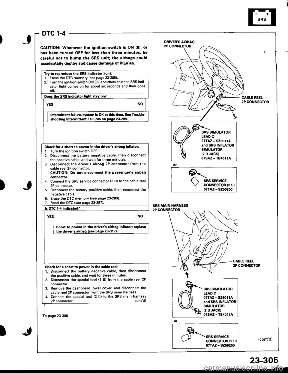
DTC 1-4
GAUTION: Whenever the ignition ewitch i! ON (ll), or
has been turned OFF tor l€ss than ihre€ minutes, be
caroful not to bump the SRS unit; tho airbag3 could
accidrnta[y deploy and caus€ damage or iniuries.
9--'-.- sns sERvrcE\,/ cli|f\FgfoR {2 ol07TAZ - SZqI200
ol
SRS SERVICEcot{ltEcToR {2 0}07TAZ - S:Zso2qt
CABLE REEL2P CONNECTOR
(cont'd)
Try to r.p.oduco tho SRS indicator light:1. Erase the DTC memory (see page 23-289).2. Turn the ignition switch ON (ll), and check that the SRS indi-
cator light comes on lor about six seconds and then goes
off.
Doo3tho SBS indic.tor light stry on?
YESNO
lnt rmittont tsiluio, systom i! (X tt thb timc. Soo Troublc
shooting Inte.mittani Failutca on P.g. 23-289.
Chock tor a shortto power in tha drivo/! ritbag inflllor:
l. Turn the ignition switch OFF.2. Disconnect the battery negativ€ cable, then disconnsct
th6 oositive cable, and wait for three minutes.
3. Disconn€ct the driver's airbtg 2P connector from the
cable reel 2P conn6ctor.CAUTION: Do not disconnost tha p!r3ong.t's rirbag
connoclor.4. Connect the SRS service connector (2 O) to the cable reel
2P connector,5. Reconnect the battery positive cable, then reconnect thenegative cabl€.6. Erase the DTC memory lsee page 23-289).7. Read the DTC (see gage 23-2aiL
|3 DTC 1-4 indicrtod?
YESNO
Shon to powa. in tha d val's tiabag itlflltor; iopl.cathe ddv.r'. airbag {t€c prge 23-317).
Check for ! short to pow.r in the cabls.oali1. Disconnect the battery negative cable. then disconnectthe positive cable, and wait for three minutes.2. Disconnect th€ special tool (2 o) from the cable reel 2P
conneclor.3. Remove the dashboard lower cover, and disconnect the
cable reel 2P connector from the SRS main harness./t. Connect the special tool (2 o) to tha SRS main harness
2P connector. (cont'd)
To page 23-306
)
,\fr)d
cffi
SRS SIMULATORLEAD C07TAZ - SZ5011Arnd SRS INFLATORSIMULATORt2 0 JACKI07SAz - TBil011A
23-305
Page 1361 of 1681
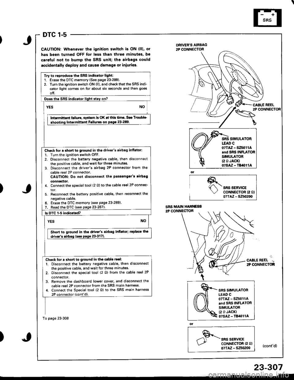
DTC 1-5
CAUTION: Whenever thc ignition switch i3 ON (lll, ot
has been turned OFF for less than throe minutss, bo
caretul not to bump the SRS unit; the airbsgs could
accidcntally deploy and cause damage or iniuri6.
DRIVER'S AIRBAG2P CONNECTOR
\"o""'"o'
CABI.E REEL
{cont'd}
)SRS SERVICECoNNECTOR 12 0)07TA2 - S250200
';
CABLEREEL.,2P OONNECTOF
)
ol
SRS SERVICECoNNECTOR (2 0l
07TAZ - SZSo2(xt
Try to ..produco the SRS indicator light:1. Erase the DTC memory (See page 23-289).2. Torn the ignition switch ON (ll), and chockrhattho SRS indi-cator light comes on for about six seconds and then goes
off.
Ooes ihe SRS indicator lighl slay on?
rffit
i .hooting ldt.rnittont Frilul.. on p.g. 23-289. I
Chock to. a 3hort to glound in tho drivor's airbag inflato.:
1. Turn the ignition switch OFF.2. Disconnect the battery nggative cable, then disconnect
the oositive cable, and wait forth.oe minutes.
3. Disconnect the driver's airbag 2P connoctor from the
cable reel 2P connector.CAUTION: Do not disconnsct tha pt!3onga]'t rirbrg
connoctor.4. Connect the special tool (2 0) to tho cable reel 2P connec_
tor,5. Reconnect tho battery positive cablo, then reconnoct the
negativ€ cable.6. Erase the DTC memory (see page 23-289)
7. Read the DTC (see pag623-2871.
k DTC 1-5 indicated?
YESNO
Sho.t to gtound in tha drive/s ri6ag infi.tor; ruplaco tho
drivor'3 .irbss (s.o p.g€ 23-3171.
Ch.ck tor a 3ho.t to gtound in tha cable ?ral:
1. Disconnect the battery negative cable. then disconnect
the oositive cable, and wait for three minutes.
2. oisconnect the special tool (2 0) lrom the cable reel 2P
connector,3. Remove the dashboard low€r cove., and disconnecl thg
cable reel 2P connector lrom the SRS main harn6ss,1. Connect the Special tool (2 0) to the SRS main harness
2P connoctor lcont'd).
To page 23-308
07TAZ - SZ50t1A.nd SRS INFLATORSIMULATOR{2 0 JACK}07SAZ - TB/OI lA
SRS SIMULATORLEAD C07TAZ - SZ501rAand SRS INFLATORSIMULATOR(2 0 JACKI07SM - TBi|t}l1A
23-307