roof rack HONDA INTEGRA 1998 4.G Workshop Manual
[x] Cancel search | Manufacturer: HONDA, Model Year: 1998, Model line: INTEGRA, Model: HONDA INTEGRA 1998 4.GPages: 1681, PDF Size: 54.22 MB
Page 892 of 1681
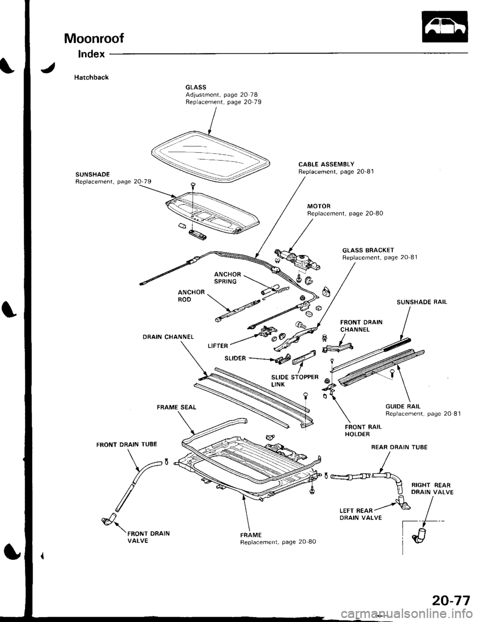
Moonroof
lndex
Hatchback
CAELE ASSEMBLYReplacement, page 20-81SUNSHAOEReplacement, page
MOTOBReplacement, page 20-80
GLASS BRACKETReplacement, page 20 81
SUNSHADE RAIL
FRONT DRAINCHANNELDRAIN CHANNEL
FRAME SEAL
FRONT DRAIN TUBE
V,
/
SLIDE STOPPERLINK
FRAMEReplacement, page 20 80
FRONT RAILHOLDER
REAR DRAIN TUSE
GUIDE RAILReplacement, page 20 81
(@
II RIGHT REARllj DRA|N vaLVE.fr/
,rr, ^*^/& IDRAIN VALVE I
[il
ir/l
@'\'FRoNT DRATNVALVE
20-77
Page 893 of 1681
Moonroof
Troubleshooting
SymptomP.obable Cause
Clogged drain tube.
Gap between glass weatherstrip and roof panel
De{ectrve or improperly Installed glass weatherstrip
Gap between drain seal and rool panel.
Excessive clearance between glass weatherstrip and roof panel-
Loose motor.
Worn gear or bearing.
Cable assemblv deformed.
1
2
3
4
1
2
3
1.
Water leaks
Wind noise
Motor noise
Glass does not move, but motor
turns
Clutch out ol adiustment.
Foreign matter stuck between guide rail and slider'
lnner cable loose.
Cable assembly not attached properly
,l
2
3
4
Glass does not move and motor
does not turn (glass can be moved
with moonroof wrench)
1. Blown fuse.
2. Faulty switch.
3. Battery run down.
4. Delective motor.
5. Faulty relay.
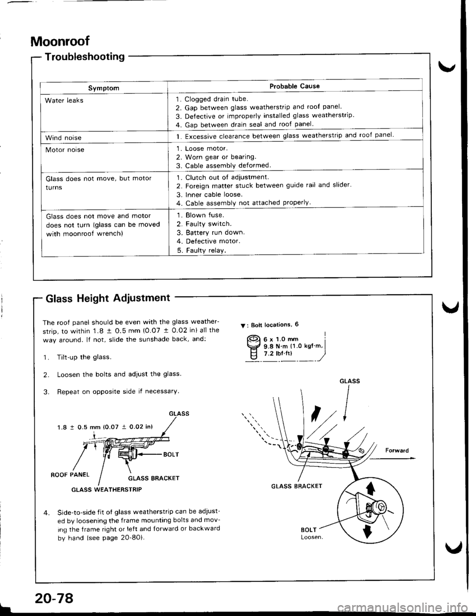
Glass Height Adiustment
The roof panel should be even with the glass weather-
srrip, to within 1.8 t O.5 mm {O.07 t 0.02 in} all the
way around. lf not, slide the sunshade back, and:
1. Tilt-up the glass.
2. Loosen the bolts and adjust the glass.
3. Repeat on opposite side if necessary.
1.8 i 0.5 mm 10.07 i 0.02 inl
V : Boll locations, 6
]-
ROOF PANELGLASS BRACKET
Side-to-side iit of glass weatherstrip can be adJust-
ed by loosening the frame mounting bolts and mov-
ing the frame right or left and {orward or backward
by hand (see page 2O-8Oi.
GLASS BRACKETGLASS WEATHERSTRIP
{
$
I
!
20-78
Page 894 of 1681
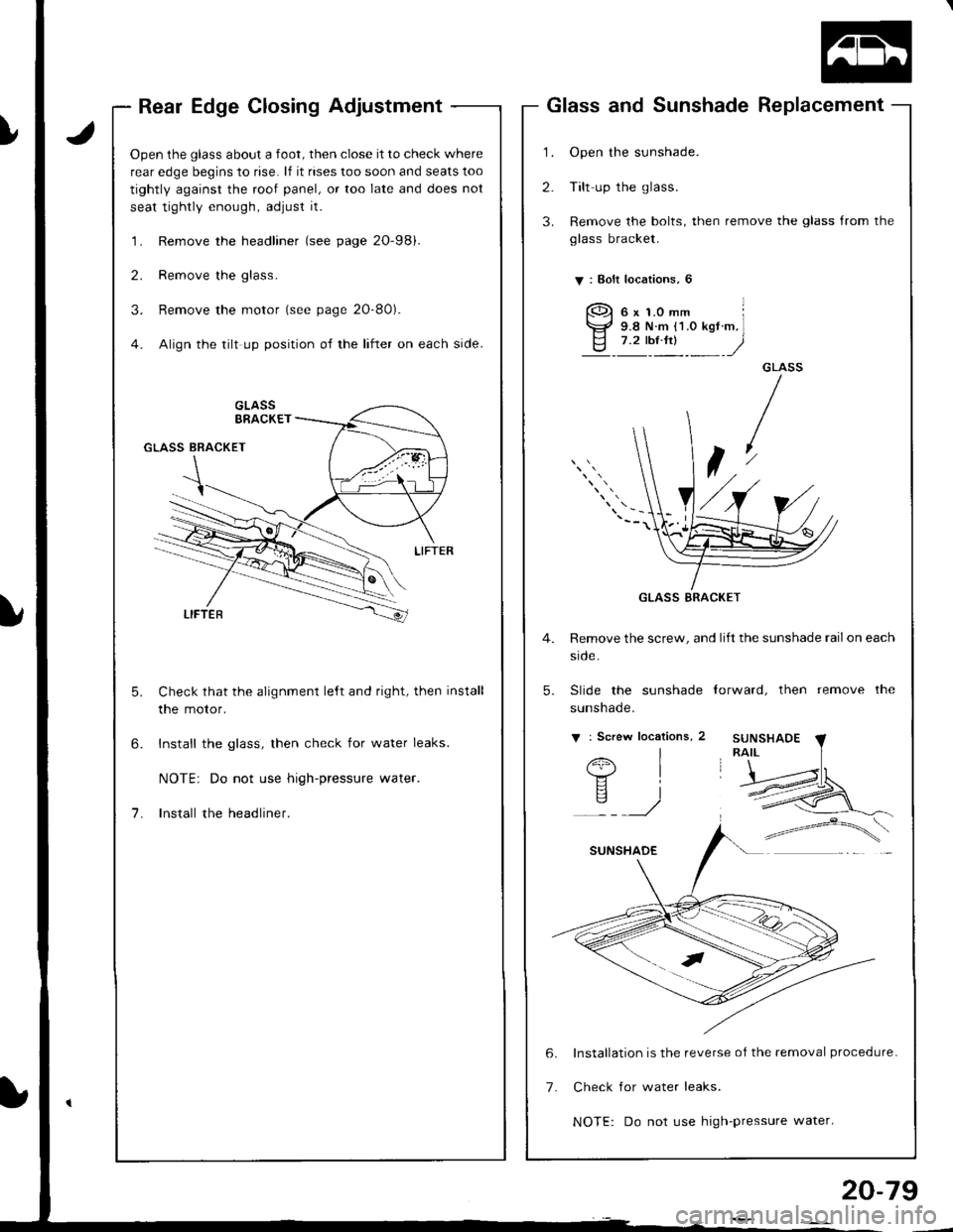
Rear Edge Closing Adjustment
Open the glass about a foot, then close it to check where
rear edge begins to rise. lf it rises too soon and seats too
tightly against the roof panel, or too late and does not
seat tightly enough, adjust it.
'l . Remove the headliner (see page 2O-98).
2. Remove the glass.
3. Remove the motor (see page 2O-80).
4. Align the tilt up position of the lifter on each side.
Check that the alignment le,ft and right, then install
the motor.
Install the glass, then check for water leaks.
NOTE: Do not use high-pressure water.
Install the headliner.
1.
2.
3.
Glass and Sunshade Replacement
Open the sunshade.
Tilt up the glass.
Remove the bolts, then remove the glass from the
glass bracket.
V : Bolt localions, 6
GLASS
t
4. Remove the screw, and lift the sunshade railon each
srcle.
5. Slide the sunshade torward, then remove the
sunshade.
v : Screw locations, 2
I
I
i
6x1.0mm l9.8 N.m {1.O kgt.m,l7.2 tbt.ftt )
Installation is the reverse of the removal procedure-
Check for water leaks.
NOTE: Do not use high-pressure water.
GLASS BRACKET
20-79
Page 897 of 1681
Moonroof
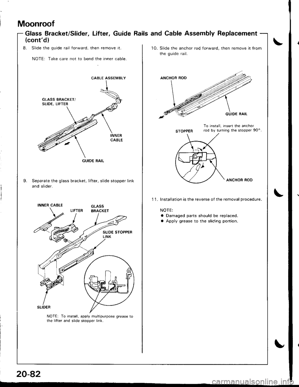
Glass Bracket/Slider, Lifter, Guide Rails and Cable Assembly Replacement
20-82
\
i
I
(cont'dl
8. Slide the guide rail forward, then remove it.
NOTE: Take care not to bend the inner cable.
10.Slide the anchor rod forward, then remove it lrom
the guide rail.
STOPPER
To install, insert the anchorrod by turning the sropper 90o
9.Separate the glass bracket, lifter, slide stopper link
and slider.
ANCHOR ROD
11.Installation is the reverse of the removal procedure.
NOTE:
a Damaged parts should be replaced.
a Apply grease to the shding portion.
INNERCABLE
\o
GLASSERACKETLIFTER
SLIOER
NOTEr To install, apply multipurpose grease tothe lifter and slide stopper link.
CABLE ASSEMBLY
GUIDE RAIL
L
Page 899 of 1681
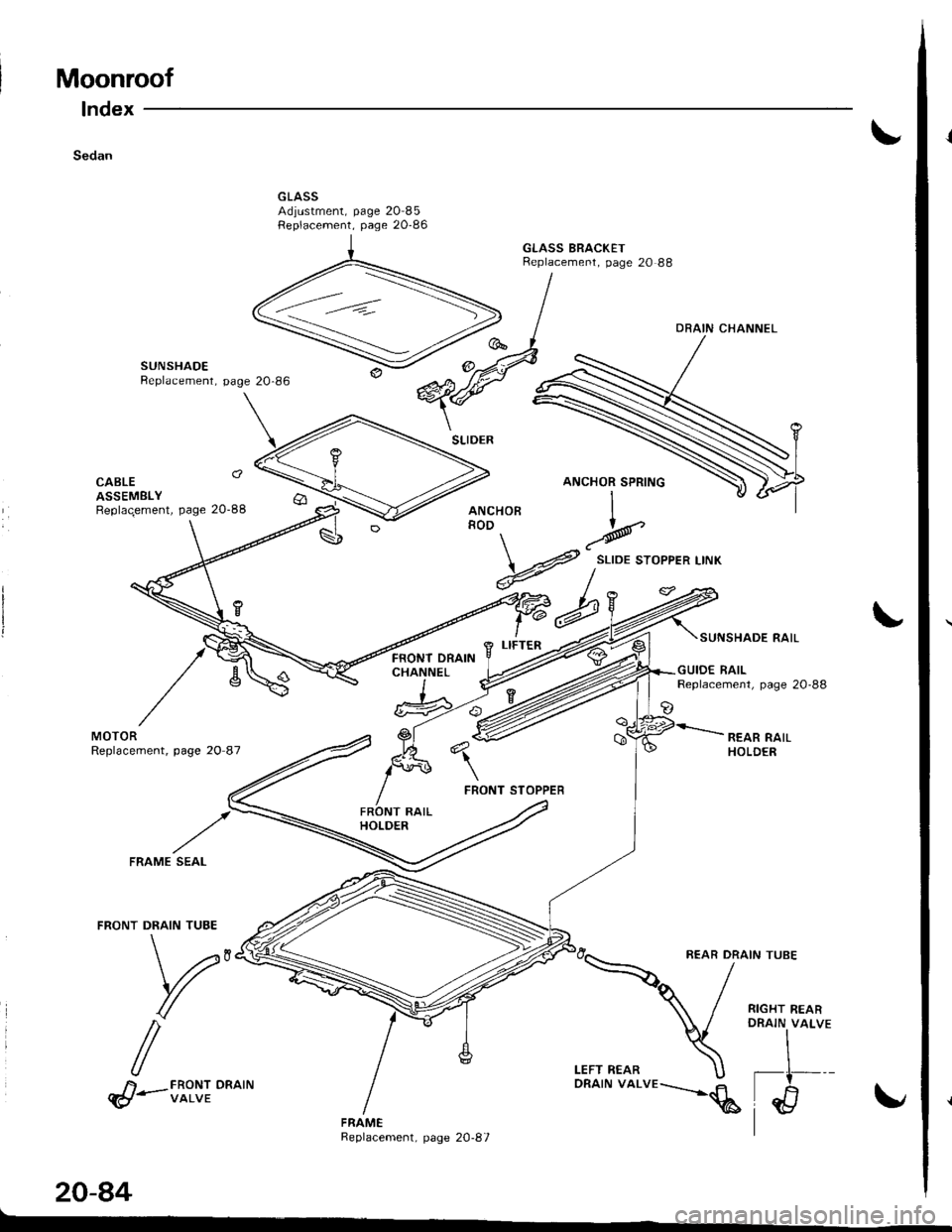
Moonroof
lndex
Sedan
GLASS BRACKETReplacement, page 20 88
SUNSHADEBeplacement, page
MOTORReplacement, page 20 87
FRONT DRAINCHANNEL
SUNSHADE RAIL
GUIOE RAILReplacemenl, page 20-88
REAR RAILHOLDER
SEAL
FRONT DRAIN TUBE
\,r,
r
/
REAR DRAIN TUBE
RIGHT REARORAIN VALVE
A FRONT ORAINq!-vawe
20-84
z=2,>
ORAIN CHANNEL
HoR I
v#,o**,"*
%bYP
FRAMEReplacement, page 20-87
\u 51-'--q€ \"
I
Page 900 of 1681
)
Troubleshooting
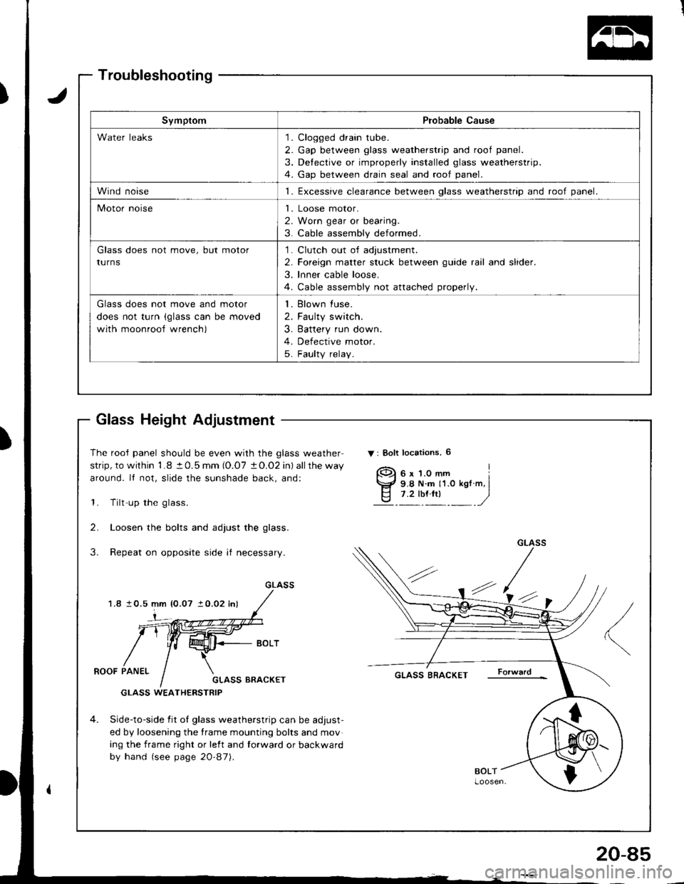
Glass Height Adjustment
The rooJ panel should be even with the glass weather
strip, to within 1.8 t 0.5 mm (O.O7 tO.O2 in) allthe way
around. It not, slide the sunshade back, and:
1. Tilt-up the glass.
2. Loosen the bolts and adjust the glass.
3. Repeat on opposite side if necessary.
1.810.5 mm {0.07 } 0.02 inl
Gr_ASS
4-(.'
ROOF PANELGLASS BRACKET
GLASS WEATHERSTRIP
4. Side-to-side fit oI glass weatherstrip can be adjust-
ed by loosening the frame mounting bolts and mov
ing the frame right or left and forward or backward
by hand (see page 20-87).
GLASS BRACKET
SymptomProbable Cause
Water leaks1. Clogged drain tube.
2. Gap between glass weatherstrip and roof panel.
3. Detective or improperly installed glass weatherstrip.
4. Gap between drain seal and roof panel.
Wind noise1. Excessive clearance between qlass weatherstriD and roof oanel.
Motor noiseI
2
3
Loose motor.
Worn gear or bearing.
Cable assembly deformed.
Glass does not move, but motor
turnS
1
2
3
Clutch out of adjustment.
Foreign matter stuck between guide rail and slider.
lnner cable loose.
Cable assembly not attached properly.
Glass does not move and motor
does not turn (glass can be moved
with moonroof wrench)
I
2
3
Blown fuse.
Faulty switch.
Battery run down.
Defective motor.
Faulty relay.5
{
s
I
20-85
Page 901 of 1681
Moonroof
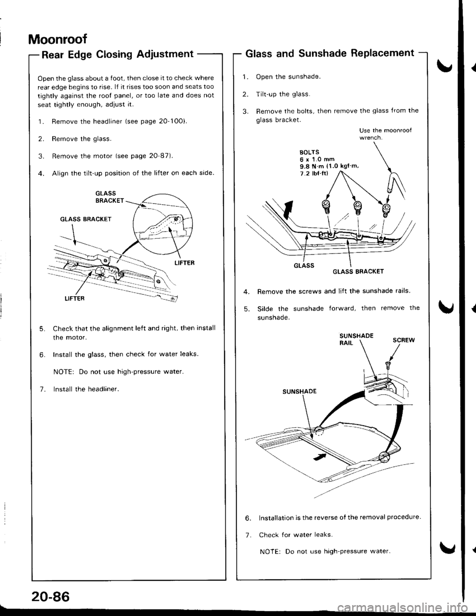
Rear Edge Closing Adjustment
Open the glass about a foot, then close it to check where
rear edge begins to rise. l,f it rises too soon and seats too
tightly against the root panel, or too late and does not
seat tightly enough, adjust it.
1. Remove the headliner (see page 20-1O0).
2. Remove the glass.
3. Remove the motor (see page 20'87).
4. Align the tilt-up position of the lifter on each side.
Check that the alignment left and right, then install
the motor.
Install the glass, then check for water leaks.
NOTE: Do not use high-pressure water.
lnstall the headliner.
20-86
Glass and Sunshade RePlacement
1. Open the sunshade.
2. Tilt-up the glass.
3. Remove the bolts, then remove the glass lrom the
glass bracket.
Use the moonroof
GLASS ERACKET
Remove the screws and lift the sunshade rails
Silde the sunshade forward, then remove the
sunsnaqe.
SUNSHADERAIL
lnstallation is the reverse ofthe removal procedure.
Check for water leaks.
NOTE: Do not use high-pressure water.
9.8 N m (1.0 kgl m,
6.
7.
Page 903 of 1681
Moonroof
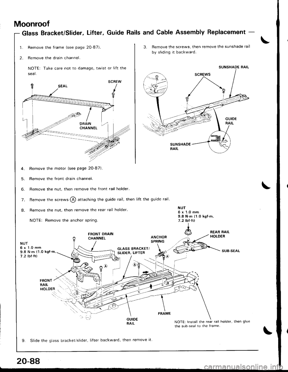
Remove the frame (see page 20-87).
Remove the drain channel.
NOTE: Take care not to damage, twist or lift the
seal.
SCREW
Remove the motor (see page 20-87).
Remove the tront drain channel.
Remove the nut, then remove the front rail holder'
Glass Bracket/Slider, Lifter. Guide Rails and Cable Assembly Replacement -
1.
2.
5.
6.
NUT6x1.0mm9.8 N m 11.0 kgf rrt,7 .2 lbl.lrl
GLASS BRACKET/SLIDER, LIFTERSUB.SEAL
rnorur / r.l .i:'r
RAIL . ',.;.
"o.ol.. i\
9. Slide rhe qldss brackel slrder, liftel backward, then remove it
NOTE: Install the rear rail holder, then glue
the sub seal to the lrame.
FRAME
20-88
3. Remove the screwg, then remove the sunshade rail
by sliding it backward.
SUNSHADERAIL
SUNSHADE RAIL
7. Remove the screws @ attaching the guide rail, then lilt the guide rail.
8. Remove the nut, then remove the rear rail holder.
NOTE: Remove the anchor spring.
FRONT DRAINCHANNEL
NUT6 x 1.0 mm9.8 N m {1.0 kgl m,
7.2 tbf ft)
L-
Page 954 of 1681
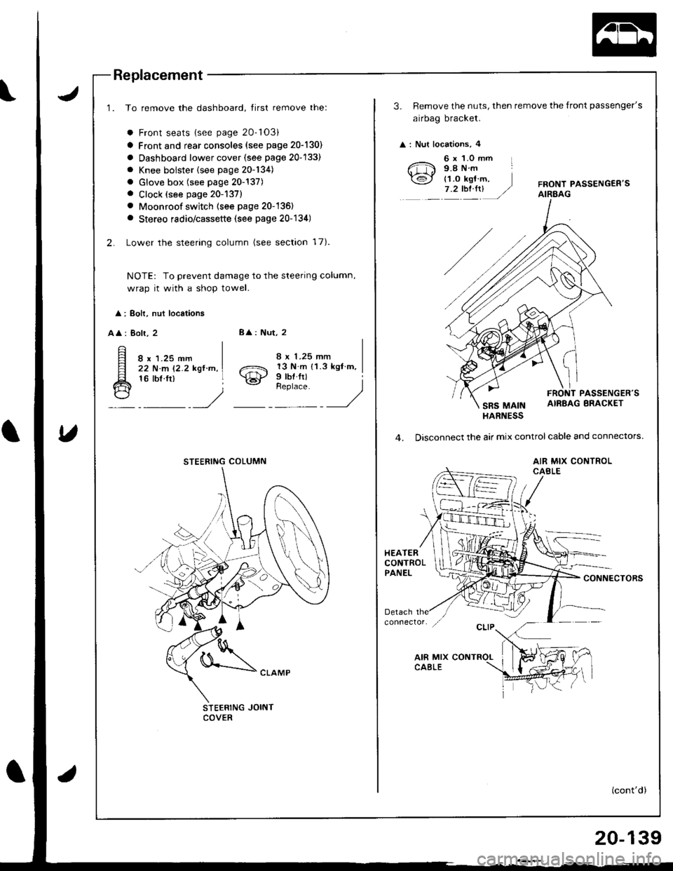
Replacement
1. To remove the dashboard, tirst remove the:
a Front seats {see page 20-'103)
a Front and rear consoles (see page 20-130)
a Oashboard lower cover {see page 20-133)
a Knee bolster (see page 20-134)
. Glove box (see page 20-137). Clock (see page 20-1371
. Moonroof switch (see page 20-136)
a Stereo radio/cassette (see page 20-134)
2. Lower the steering column (see section 17).
NOTE: To prevent damage to the steering column,
wrap it with a shop towel.
l ; Boh, nut locations
AA : Bolr, 28
: Nut, 2
8 x 1.25 mm22 N.m 12.2 kgl.n,16 tbf.ft)o21 13 N m 11.3 kgl m,
\€J' Prbl rll
_Urr'rr,t __)
STEERING JOINTCOVER
STEERING COLUMN
3. Remove the nuts, then remove the front passenger's
airbag bracket.
: Nut locations, 4
6 x 1.0 mm L9.8Nm
{1.o kgt m,7.2tbt.rrUFRONT PASSENGEB'SAIRBAG
PASSENGER'S
SRS MAINAIRBAG BRACKET
HARNESS
4. Disconnect the air mix control cable and connectors.
AIR MIX CONTROLCABLE
HEATERCONTROLPANELCONNECTORS
(cont'd)
20-139
Page 979 of 1681
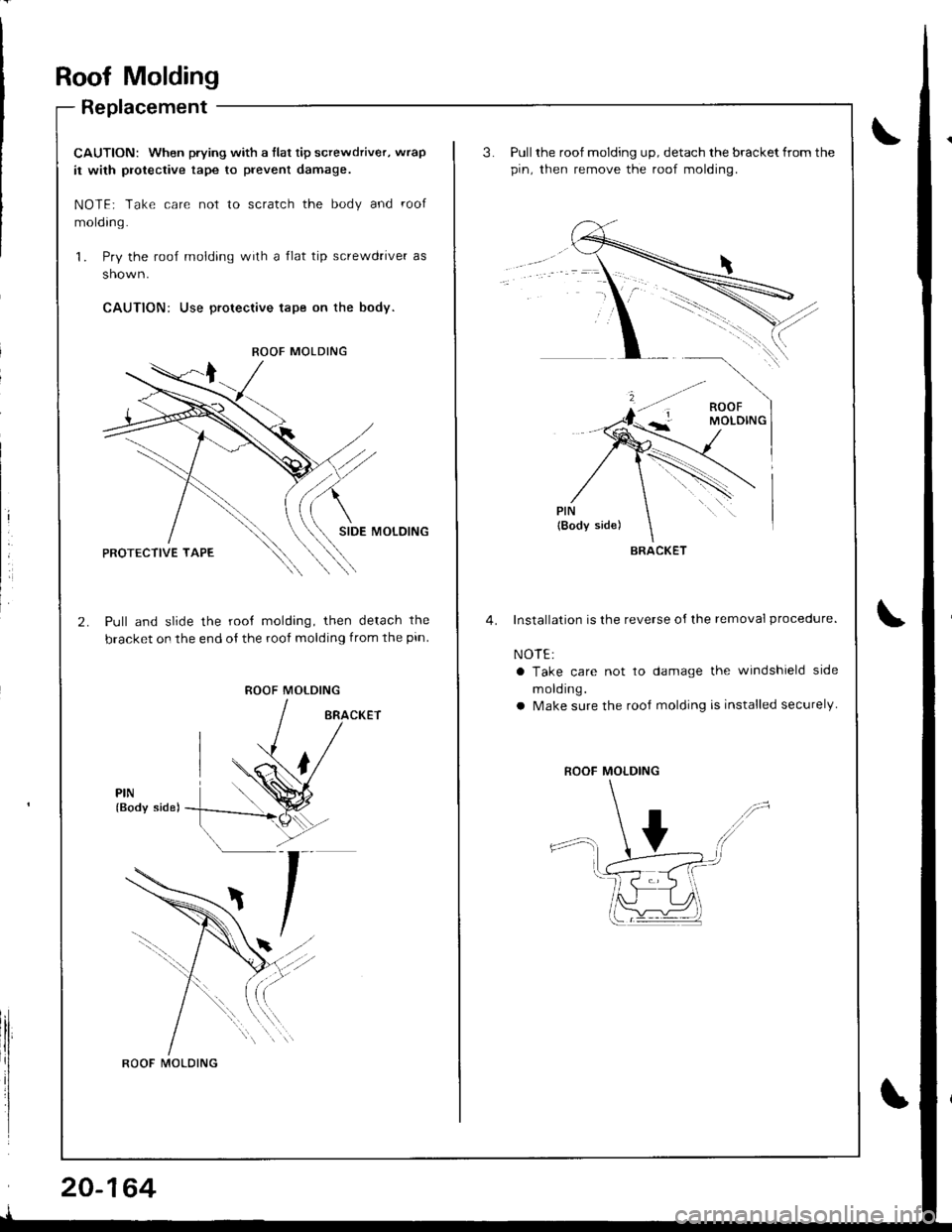
Roof Molding
Replacement
CAUTION: When prying with a flat tip screwdriver, wrap
it with protective tape to prevent damage.
NOTE; Take care not to scratch the body and roof
molding.
1. Pry the roof molding with a flat tip screwdrive. as
shown.
CAUTION: Use proteclive tape on the body.
SIDE MOLOING
Pull and slide the root molding, then detach the
bracket on the end of the roof molding from the pin
ROOF MOLDING
PIN(Body side)
ROOF MOLDING
ROOF MOLDING
20-164
Pull the roof molding up, detach the bracket from the
pin. then remove the roof molding.
Installation is the reverse oI lhe removal procedure.
NOTE:
a Take care not to damage the windshield side
m old ing.
a Make sure the rooJ molding is installed securely
BRACKET
ROOF MOLDING