wheel HONDA INTEGRA 1998 4.G Owner's Manual
[x] Cancel search | Manufacturer: HONDA, Model Year: 1998, Model line: INTEGRA, Model: HONDA INTEGRA 1998 4.GPages: 1681, PDF Size: 54.22 MB
Page 511 of 1681
Road Test
NOTE: Warm up the engine to operating temperature (the radiator fan comes on).
1. Apply parking brake and block the wheels. Start the engine, then shift to @ position while depressing the brake pedal-
Depress the accelerator pedal, and release it suddenly. The engine should not stall.
2. Repeat same test in E position.
3. Test drive the vehicle on a flat road in the @ position. Check that the shift points occur at approximate speeds shown.
Also check for abnormal noise and clutch slippage.
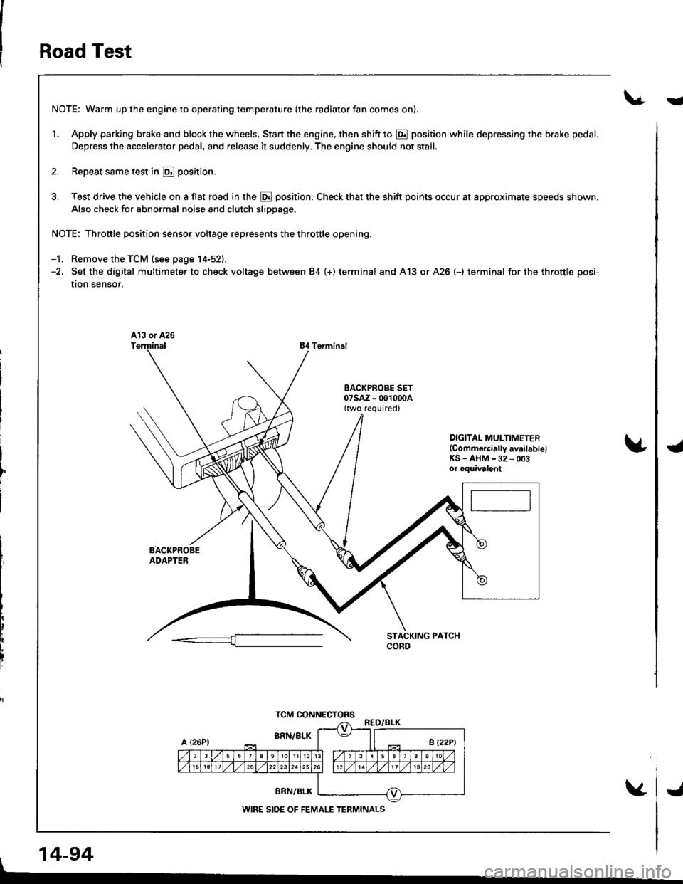
NOTE: Throttle position sensor voltage represents the throttle opening.
-1. Remove the TCM (see page 14-52).-2. Set the digital multimeter to check voltage between 84 (+) terminal and A13 or A26 (-) terminal for the throttle posi-
tion sensor.
84 Terminal
DIGITAL MULTIMETER(Commercially availablelKS - AHM -32 - 003oa oquivalent
, 14-94
TCM CONNECTORS
WIRE SIDE OF FEMALE TERMINALS
i
J
Page 514 of 1681
Stall Speed
V
€nt transmission damage, do not tost stall speod for mol€ than
shitt tho lever while raising the engina speed,
10 soconds at a time.
L
CAUTION:
a To prev€nt transmission damage, do not tost stall speod for mol€ than 10 soconds at a time.
a Do not shitt tho lever while raising the engina speed,
a Be suro to remove tho plossule gaugo bolore testing st8ll spe€d.
1. Engage the parking brake. and block all lour wheels.
2. Connect the tachometer, and start the engine,
3. Make sure the A/C switch is OFF.
4. After the engine has warmed up to normal operating temperature {the radiator fan comes on), shift into g position.
5. Fully depress the brake pedal and accelerator for 6 to I seconds. and note engine speed.
6. Allow two minutes for cooling, then repeat the test in [, [Dll and @ oositions.
NOTE:
a Stall speed tests should be used tor diagnostic purposes only.
. Stall speed should be the same in E, tr, tr and @ Fositions.
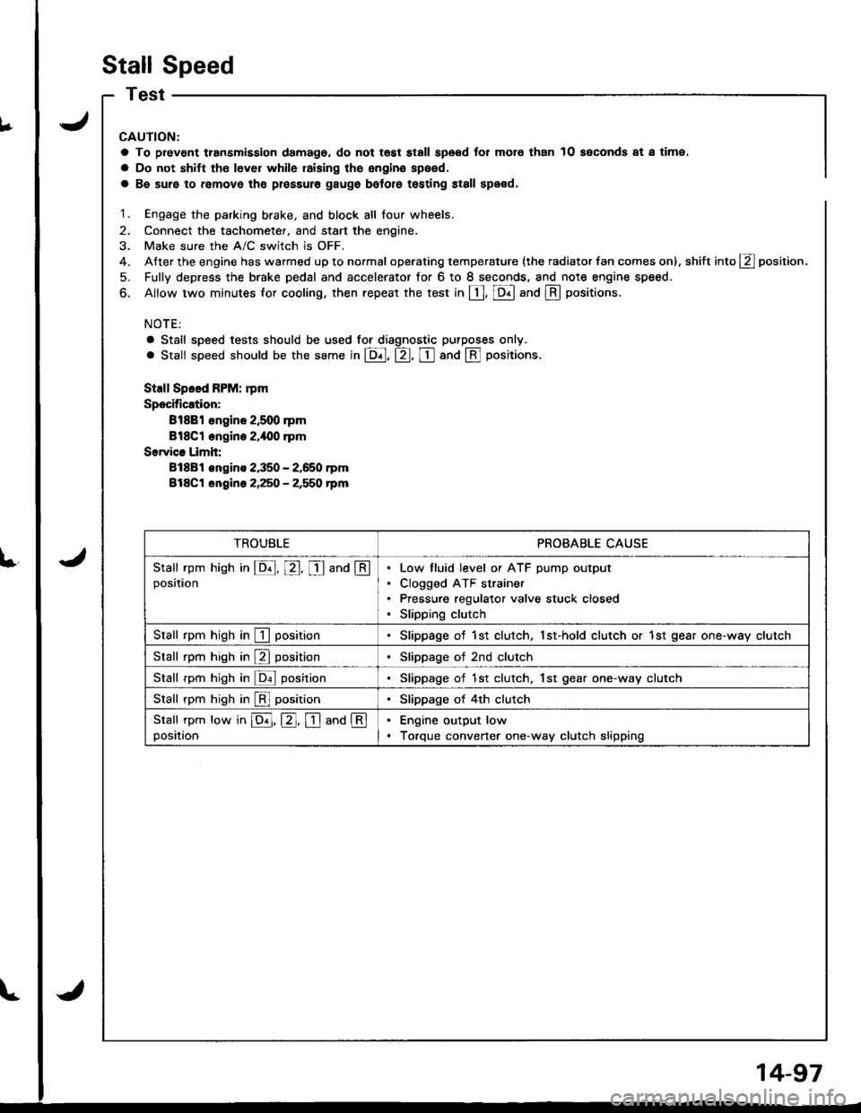
Stall Speed FPM: rpm
Specification:
Bl88l €ngine 2,5q) rpm
Bl8Cl engine 2.i|{10 .pm
Sorvice Limit:
81881 engins 2,350 - 2,650 rpm
Bl8Ct ongine 2,250 - 2,550 rpm
TROUBLEPROBABLE CAUSE
Stall rpm hish in E, E, I and @position
Low tluid level or ATF pump output
Clogged ATF strainer
Pressure regulator valve stuck closed
Slipping clutch
Stall rpm high in I positionSlippage of 1st clutch, 1st-hold clutch or 1st gear one-way clutch
Stall rpm high in E positionSlippage of 2nd clutch
Stall rpm high in ldnl posirionSlippage of 1st clutch. 1st gear one-way clutch
Stall rpm high in [!l positionSlippage of 4th clutch
Stall rpm low in E, E. I and @position
Engine output low
Torque convener one-way clutch slipping
14-97
Page 516 of 1681
Pressure Testing
a While testing, be careJulot the rotating front wheels.
a Make sule litts, iacks, and safety stands are placed
properly (see section 1).
CAUTION: Befoie testing, be sure the transmission fluid
is filled to the proper level.
'1. Raise the vehicle {see section 'll.
2. Warm up the engine (the radiator fan comes on),
then stop the engine and connect a tachometer.
3. Connect the special tool to each inspection hole(s).
TOROUE: 18 N.m l1-8 kgt.m, 13lbf.ftl
CAUTION: Connect the A/T pressure gauge secure-
ly, be sure not to allow dust and olher foreign pani-
cles to enter the inspection hole.
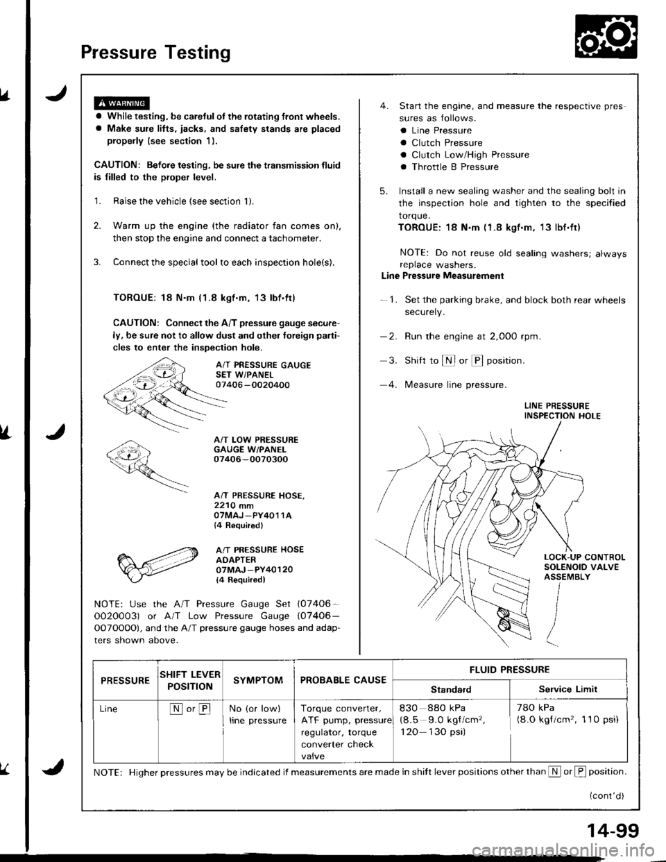
A/T PRESSURE GAUGESET W/PANEL07406 -0020400
A/T LOW PRESSUREGAUGE W/PANEI.07406-OO70300
A/T PRESSURE HOSE,2210 mmOTMAJ _PY4O1 1A{4 Required}
A/T PRESSURE HOSEADAPTER07MAJ -PY40120
l4 Requiredl
NOTE: Use the A/T Pressure Gauge Set (07406-
OO2O0O3) or A/T Low Pressure Gauge (07406-
OOTOOOO), and the A/T pressure gauge hoses and adap-
ters shown above.
4. Start the engine, and measure the respective pres
sures as follows.
a Line Pressure
a Clutch Pressure
a Clutch Low/High Pressure
a Throttle B Pressure
5. Install a new sealing washer and the sealing bolt in
the inspection hole and tighten to the specified
torque.
TOROUE:18 N.m (1.8 kgf.m, 13lbf.ft)
NOTE: Do not reuse old sealing washers; alwaysreplace washers.
Line Pressure Measurement
-1. Set the parking brake, and block both rear wheels
securely.
-2. Run the engine at 2,000 rpm
3. Shift to S or @ position.
4. lMeasure line pressure.
LINE PRESSUREINSPECTION HOLE
LOCK-UP CONTROLSOLENOID VALVEASSEMBLY
PRESSURESHIFT LEVER
POST ONSYMPTOMPROBABLE CAUSEFLUID PRESSURE
StandardService Limit
LineNo,BNo (or low)
Irne pressure
Torque converter,
ATF pump, pressure
regulator, torque
converter check
830 88o kPa
(8.5 9.O kgf/cm'�,
1 20 130 psi)
78O kPa(8.O kgf/cm'�, 1 10 psi)
NOTE: Higher pressures may be indicated if measurements are made in shitt lever positions other than S or f, position.
{cont'd )
14-99
Page 517 of 1681
Pressure Testing
.Y
Clutch P.6ssure Measuremgnt
@ wnirc testing. be caretul ot the rorating tront wheels.
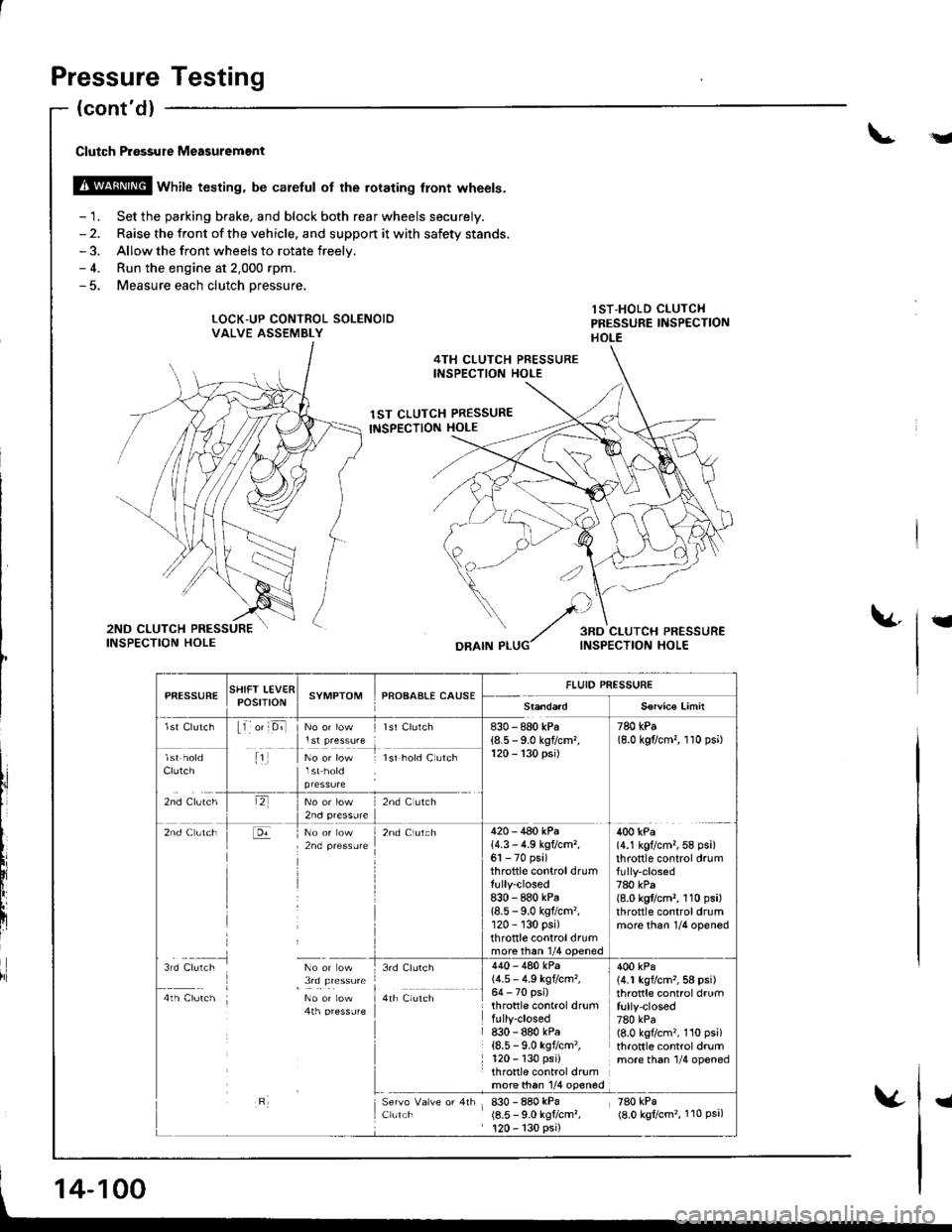
- 1. Set the parking brake, and block both rear wheels securely.- 2. Raise the front of the vehicle, and support it with safety stands.- 3. Allow the front wheels to rotate freelv.- 4. Run the engine at 2.000 rpm.- 5. Measure each clutch oressure.
LOCK"UP CONTROL SOLENOIDVALVE ASSEMBLY
lST-HOLD CLUTCHPRESSURE IiISPECTIONHOLE
4TH CLUTCH PRESSUREINSPECTION HOLE
1ST CLUTCH PRESSURE
INSPECTION HOLE
t
DRAIN P
l,i
PfiESSURESTIIFT LEV€RPOStTtONSYMPTOMPROAAALE CAUSEFLUID PRESSURE
S€rvico Limit
lst Clutch11 o' D;llst Clurch830 - 880 kPa(8.5 - 9.0 kgflcm,120 - 130 psi)
780 kPa(8.0 kgflcm,, 1 10 psi)
Clutch
zno cruiltr
1No or low lsr hold C utch
lr,2nd C ltch
2nd Clutch420 - 440 kPa14.3 - 4.9 kg?cm,,61 - 70 psi)throttle controldrumtully-closed8:|0 - 880 kPa18.5 - 9.0 kgflcm'�,120 - 130 psi)throttle controldrummore than 1/4 ooened
400 kPa(4.1 kg?cm,,58 psi)throttle control drum
780 kPa(8.0 kgflcm,, 110 psi)throttle controldrummore than 1/4 opened
3rd Clulch No or ow
I , !,q !le"**4th Clutch No or Low4th pressufe
3rd Clurch
a,r il","r,
Clulch
440 - 480 kPa(4.5 - 4.9 kgtcm,,64 - 70 psi)throttle control drumfully-closed830 - 880 kPa{8.5 - 9.0 ksf/cm'�,120 - 130 psi)throttle control drumrn9l9!q l/4 olqg
830 - 880 kPa(8.5 - 9.0 kgtcm?,120 - 130 psi)
400 kPa14.1 kgvcm,,58 psi)throttle control drumfully-closed780 kPa(8.0 kgflcm'�, 110 psi)throttle control drummore th6n 1/4 opened
zeo rpi(8.0 kgtcm'�, 110 Psa,
14-100
I
Page 518 of 1681
\a
t
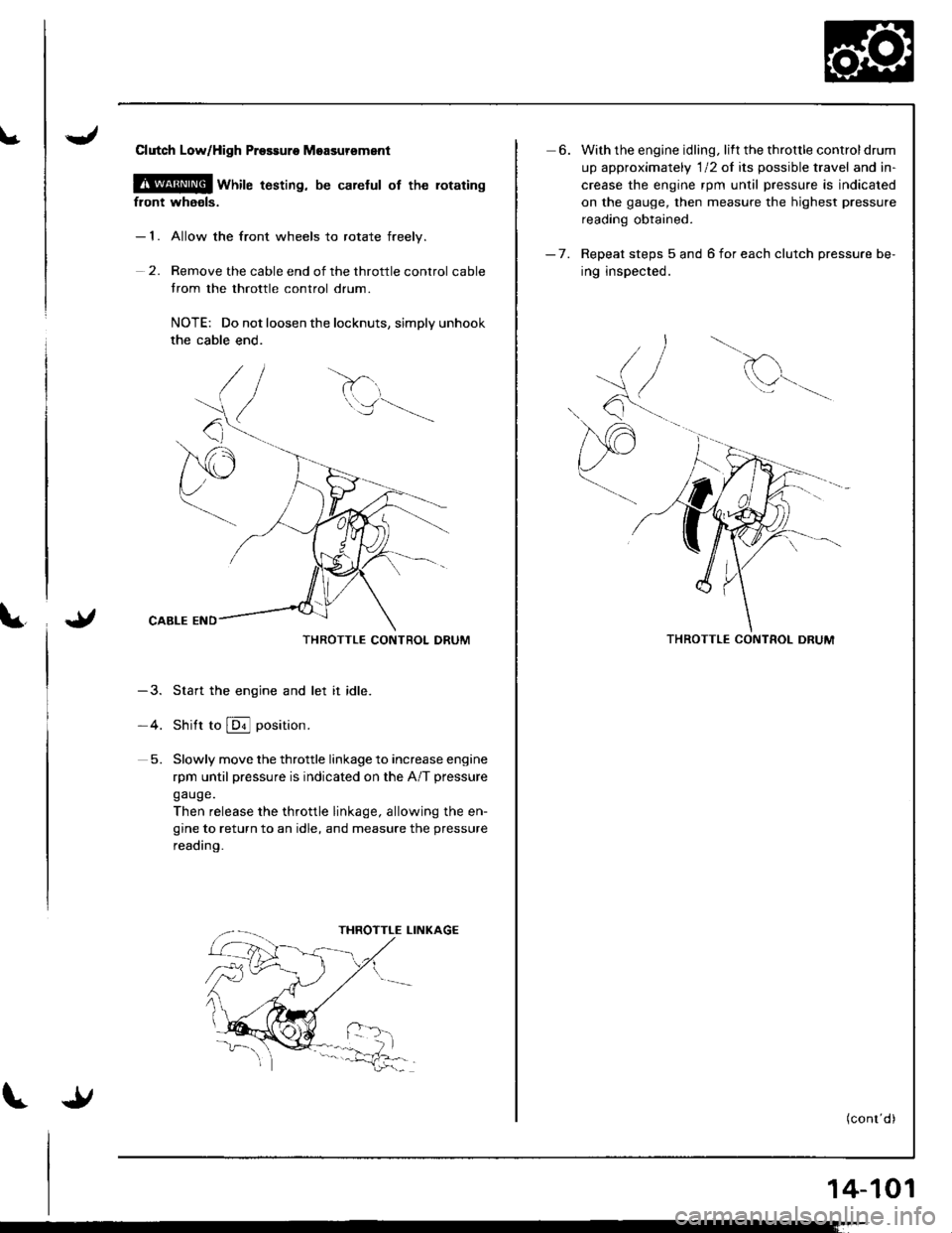
Clutch LoWHigh Prossuro Moasursment
@ wnire t6sting, be carelul of the rotating
front whaols.
- 1. Allow the front wheels to rotate freelv.
2. Remove the cable end of the throttle control cable
trom the throttle control drum.
NOTE: Do not loosen the locknuts, simply unhook
the cable end.
THROTTLE CONTROL DRUM
-3. Start the engine and let it idle.
-4. Shitt to @ position.
5. Slowly move the throttle linkage to increase engine
rpm until pressure is indicated on the A/T pressure
gauge.
Then release the throttle linkage, allowing the en-
gine to return to an idle, and measure the pressure
reading.
6. With the engine idling. lift the throttle controldrum
up approximately 'l12 of its possible travel and in-
crease the engine rpm until pressure is indicated
on the gauge, then measure the highest pressure
reading obtained.
- 7. Repeat steps 5 and 6 for each clutch pressure be-
ing inspected.
d
Q^--,'.-
THROTTLE CONTROL DRUM
(conr'd)
14-101
Page 520 of 1681
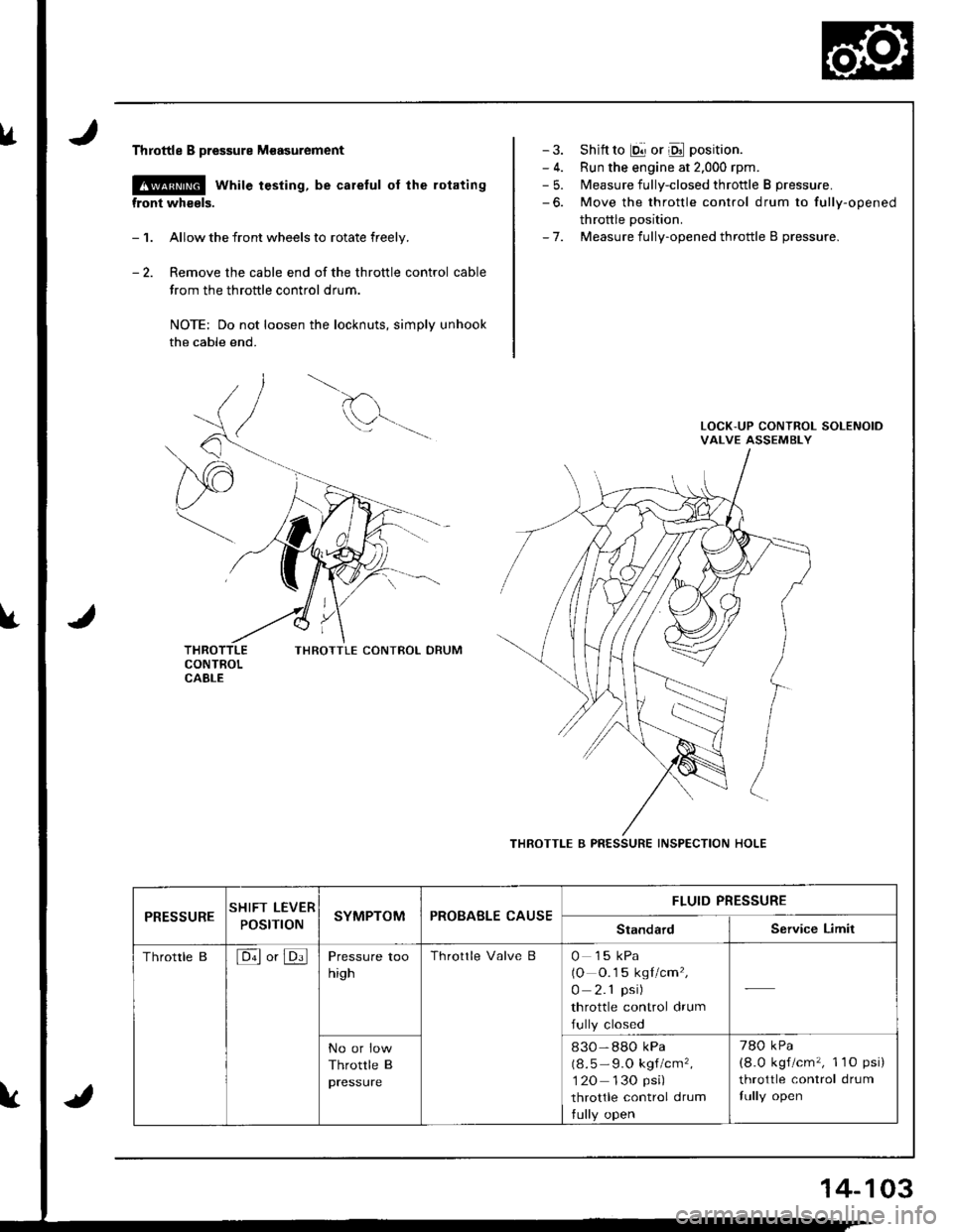
lrThrottle B pressure M€asurement
@ while testing, be careful of the rotating
front wheels.
- 1. Allow the front wheels to rotate freely.
- 2. Remove the cable end of the throttle control cable
trom the throttle control drum.
NOTE: Do not loosen the locknuts, simply unhook
the cable end.
THROTTLE CONIBOL DRUM
- 3. Shift to E!] or Oll position.
- 4. Run the engine at 2.000 rpm.- 5. Measure fully-closed throttle B pressure.
-6. Move the throttle control drum to fully-opened
throttle Dosition.- 7. Measure fully-opened throttle B pressure.
THROTTLE B PRESSURE INSPECTION HOLE
PRESSURESHIFT LEVER
POStnONSYMPTOMPROBABLE CAUSEFLUID PRESSURE
StandardService Limit
Throttle B[6ll or JDi]Pressure too
high
Throttle Valve B0 15 kPa(O O.1 5 kgl/cm',
0 2.1 psi)
throttle control drum
fully closed
No or low
Throttle B
pressure
830-88O kPa
(8.5 - 9.O kgf/cm',
1 20 130 psi)
throttle control drum
tully open
780 kPa
(8.0 kgf/cm'�, 1 1O psi)
throttle control drum
fully open
14-103
Page 521 of 1681
Transmission
Removal
. Make sure lifts, iacks and salety stands are placed
properly, and hoist brackets are attached to lhe cor-
rect position on the engine (see section 11.
. Apply parking brake and block real wheels, so vehi-
cle will nol roll off stands and fall on you while work-
ing under it.
CAUTION: Use fender covers to avoid damaging paint-
ed surtaces.
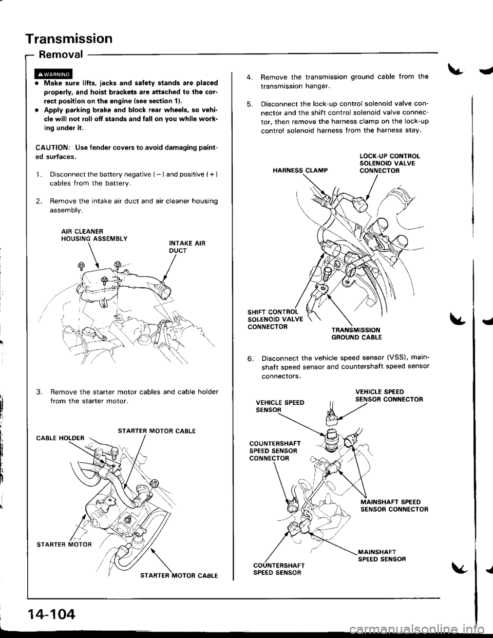
1 . Disconnect the battery negative (- ) and positive { + )
cables from the battery.
2. Remove the intake air duct and air cleaner housing
assemoty.
AIR CLEANERHOUSING ASSEMBLY
Remove the starter motor cables and cable holder
from the starter motor.
MOTOR CABLECABLE HOLDER
STARTER MOTOR'/,/ \
STARTER MOTOR CABI-E
14-104
-
5.
Remove the transmission ground cable from the
transmission hanger.
Disconnect the lock-up control solenoid valve con-
nector and the shift control solenoid valve connec-
tor, then remove the harness clamp on the lock-up
control solenoid harness from the harness s1ay.
HARNESS CLAMP
TRANSMISSIOIGROUND CABLE
Disconnect the vehicle speed sensor (VSS), main-
shalt speed sensor and countershalt speed sensor
connecrors.
{
6.
VEHICLE SPEED
VEHICLE SPEED
ll t2tor coNNEcroR
V
MAINSHAFT SPEEDSENSOR CONNECTOR
MAINSHAFTSPEED SENSORCOUNTERSHAFTSPEED SENSOR{
Page 587 of 1681
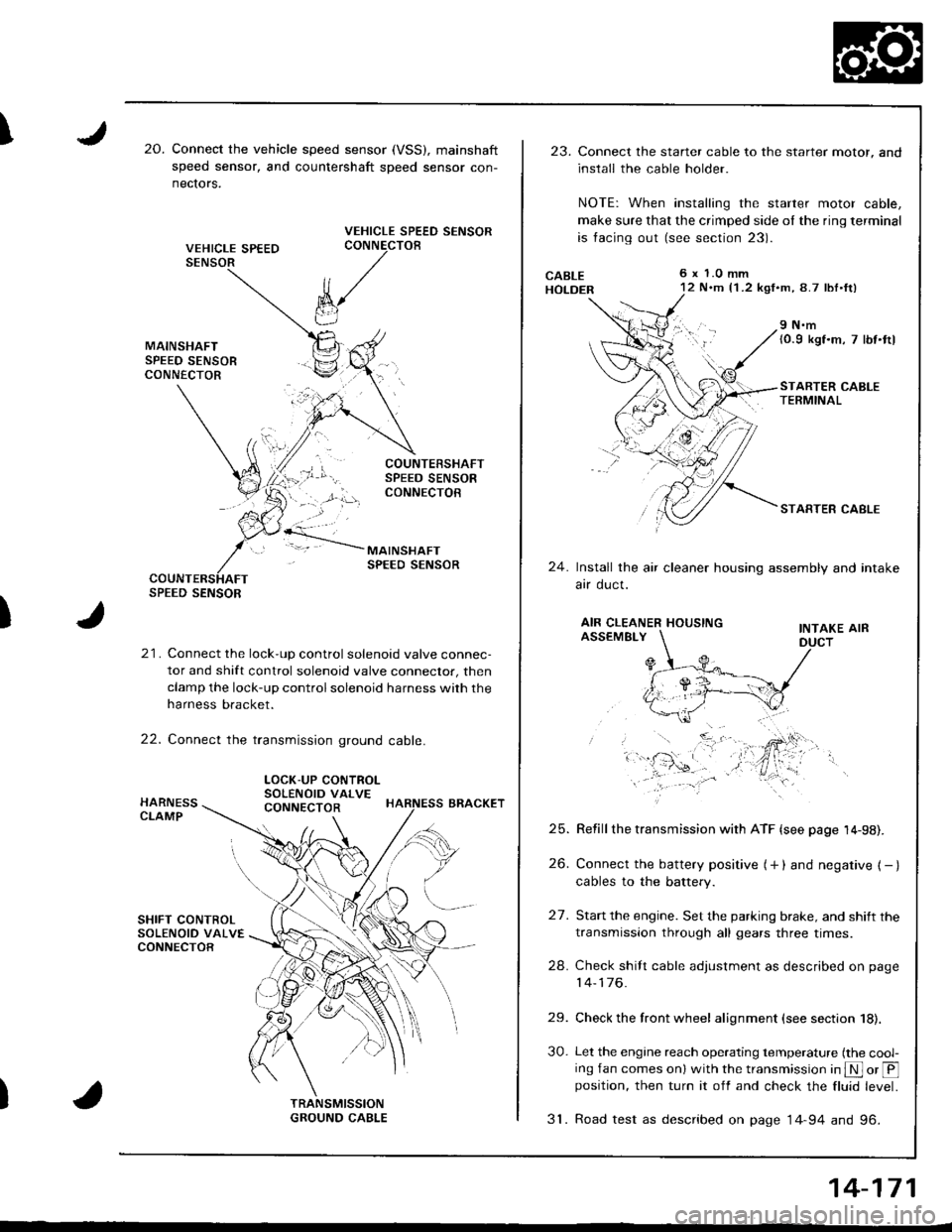
I20.Connect the vehicle speed sensor (VSS), mainshaft
speed sensor, and countershaft sDeed sensor con-
nectors.
VEHICLE SPEED SENSORCONNECTOB
)
k/
t"J
21. Connect the lock-up control solenoid valve connec-
tor and shift control solenoid valve conneclor, then
clamp the lock-up control solenoid harness with the
harness bracket.
22. Connect the transmission ground cable.
SPEED SENSOR
LOCK-UP CONTROLSOLENOID VALVECONNECTOR
23.Connect the starter cable to the starter motor, and
install the cable holder.
NOTE: When installing the starter motor cable,
make sure that the crimped side ol the ring terminal
is facing out (see section 23).
6 x 1.0 mm12 N.m {1 .2 kgf.m, 8.7 lbl.ft)
9 N.m(0.9 kgf.m, 7 lbt.ttl
STARTER CABLETERMINAL
STARTER CABLE
24.Install the air cleaner housing assembly and intake
arr oucl.
AIR CLEANER HOUSINGINTAKE AIRASSEMBLY
27.
Refill the transmission with ATF {see page 14-98).
Connect the battery positive (+ ) and negative { - }cables to the battery.
Start the engine. Set the parking brake, and shift the
transmission through all gears three times.
Check shilt cable adjustment as described on page
14-176.
Check the front wheel alignment (see section 18).
Let the engine reach operating temperature (the cool-ing fan comes onl with the transmission in S or @position, then turn it off and check the fluid level.
31. Road test as described on page 14-94 and 96.
25.
26.
24.
29.
30.
14-171
Page 618 of 1681
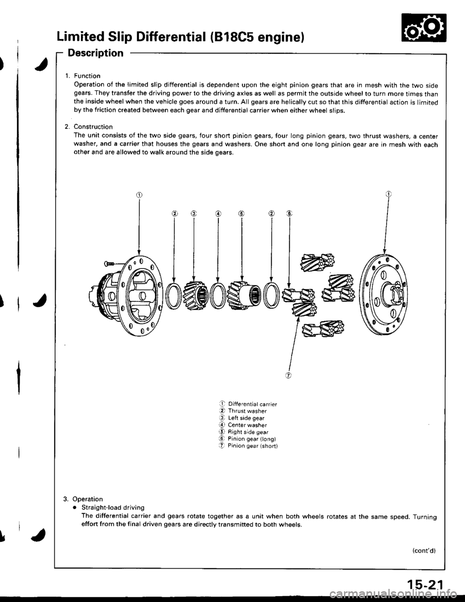
Limited Slip Differential (818C5 engine)
Description
t
f1t
1. Function
Operation of the limited slip differential is dependent upon the eight pinion gears that are in mesh with the two sidegears. They transfer the driving power to the driving axles as well as permjt the outside wheel to turn more times thanthe inside wheel when the vehicle goes around a turn. All gears are helically cut so that this differential action is limitedby the friction created between each gear and differential carrier when either wheel slips.
2. Construction
The unit consists of the two side gears, four short pinion gears, four long pinion gears, two thrust washers, a centerwasher, and a carrier that houses the gears and washers. One shon and one long pinion gear are in mesh with eachother and are allowed to walk around the side oears.
w
I
I
I
+
@
a,
e Differentiatcarrier
a Thrust washer
@ Left side gear
O Center washerg Right side gear
O Pinion gear ong)O Pinion gea r (short)
Ooeration
. Straight-load driving
The differential carrier and gears rotate together as a unit when both wheels rotates at the same speed. Turningeffon from the final driven gears are directly transmitted to both wheets.
(cont'd)
l,'a
15-21
Page 619 of 1681
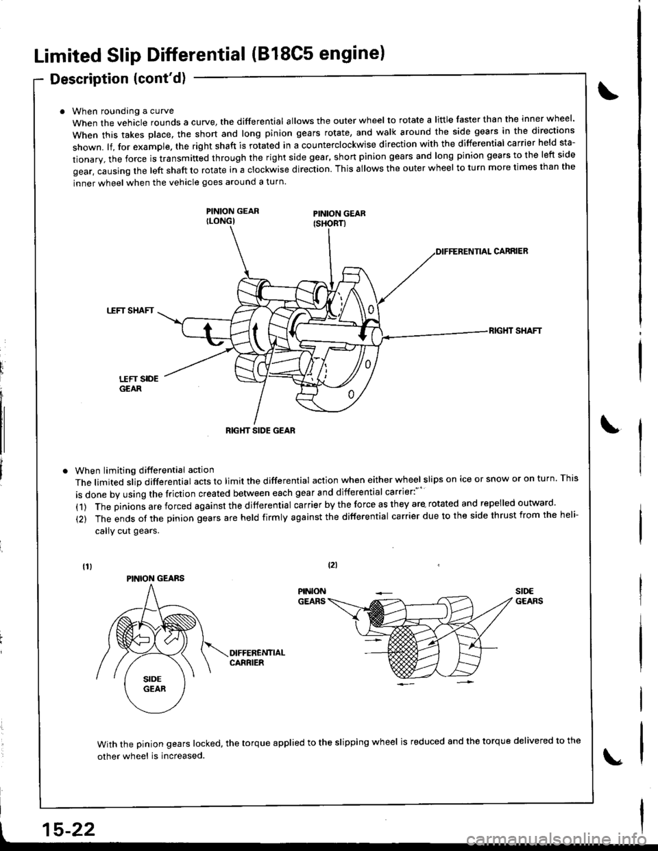
Limited Slip Differential (B18C5 engine)
Description (cont'd)
When roundang a curve
When the vehacle rounds a curye, tne differential allows the outer wheel to rotate a little faster than the inner wheel.
when this takes p|ace. the short and |ong pinion gears rotate, and wa|k around the side gears in the directions
shown. lf, for example. the right shaft is rotated in a counterclockwise direction with the differential carrier held sta-
tionary, the force is transmitted through the right side gear, short pinion gears and long pinion gears to the left side
gear, causing the left shaft to rotate in a clockwise direction. This allows the outer wheel to turn more times than the
inner wheel when the vehicle goes around a turn.
PINION GEARILONG)
When limiting differential action
The limited slip differential acts to limit the differential action when either wheel slips on ice or snow or on turn. This
is done by using the friction created between each gear and differential carrier:"''
(1) The pinions are forced against the differential carrier by the force as they are- rotated and repelled outward.
(2) The ends of the pinion gears are held firmly against the differential carrier due to the side thrust from the heli-
callY cut gears.
CARRIEB
TTFT SHAFT
RIG}IT SHAFT
With the pinion gears locked, the torque applied to the slipping wheel is reduced 8nd the torque delivered to the
other wheel is increased.
tzl
t15-22
RIGHT SIDE GEAR
PINION GEARS