wheel HONDA INTEGRA 1998 4.G Repair Manual
[x] Cancel search | Manufacturer: HONDA, Model Year: 1998, Model line: INTEGRA, Model: HONDA INTEGRA 1998 4.GPages: 1681, PDF Size: 54.22 MB
Page 716 of 1681
l,
Wheel Alignment
Turning Angle Inspection
NOTE: Use commercially-available computerized four
wheel alignment equipment to measure wheel align-
ment (caster, camber, toe, and turning angle). Follow
the equioment manufacturer's instructions.
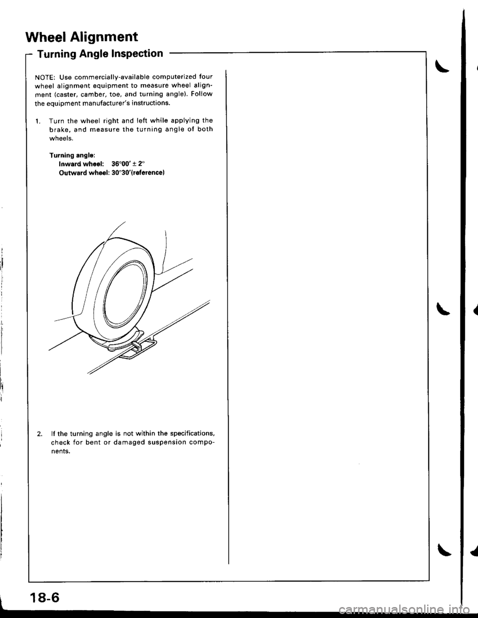
1. Turn the wheel right and left while applying the
brake, and measure the turning angle of both
wneels.
Turning angle:
lnward whsol: 36'00't 2"
Outward wheel: 30'30'{rotorencel
lf the turning angle is not within the specifications.
check for bent or damaged suspension compo-
nenrs.
18-6
Page 717 of 1681
Wheel/Hub Inspection
Bearing End Play
Raise the vehicle off the ground, and support it with
safety stands in the proper locations (see saction 1).
Remove the wheels, then reinstallthe whe6l nuts.
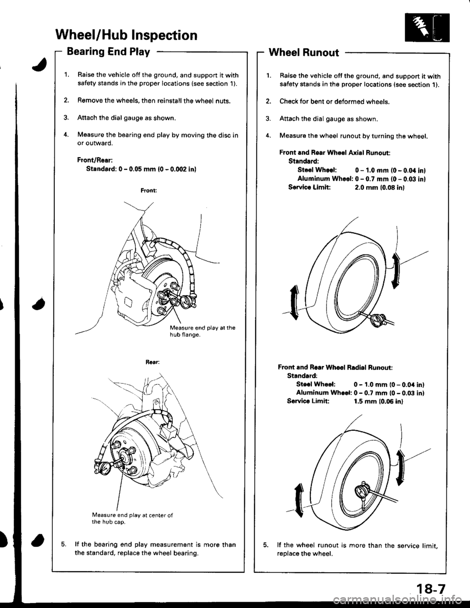
Attach the dial gauge as shown.
Measure the bearing end play by moving the disc in
or outward.
Front/Rear:
Standa.d: 0 - 0.05 mm (0 - 0.qr2 in)
a
Measure end play at center ofthe hub cap.
lf the bearing end play measurement is
the standard, replace the wheel bearing.
Wheel Runout
Raise the vehicle off the ground, and support it withsatety stands in the proper locations (see section 1).
Check for bent or deformed wheels.
Attach the dial gauge as shown.
Measure the wheel runout by turning the wheel.
Front and Roar Whool Axial Runout:
Standard:
Stcsl Whoel: 0 - 1.0 mm (0 - 0.04 inl
Aluminum Whcel: 0 - 0.7 mm (0 - 0.03 inl
Sorvlc. Limit:2.0 mm (0.08 inl
Front End Roar Whod Rldisl Runouti
Standard:
Ste.l Whool: 0 - 1.0 mm (0 - 0.04 inlAluminum Wh.el: 0 - 0.7 mm (0 - 0.03 inl
Sorvico Limit:1.5 mm (0.06 inl
lf the wh€el runout is more than the service limit,
reDlace the wheel.
more than
18-7
Page 719 of 1681
Knuckle/Hub
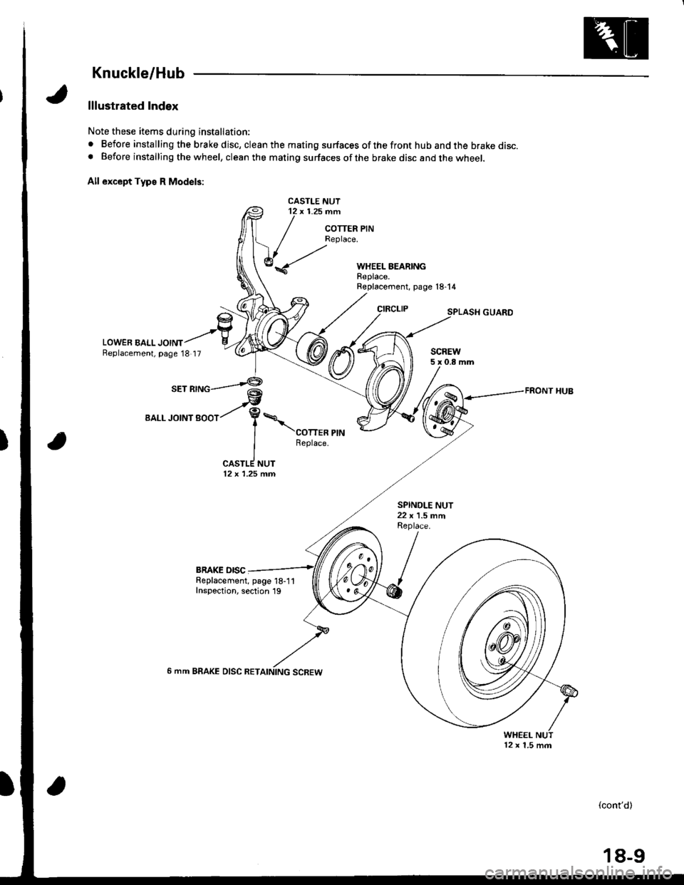
lllustrated Index
Note these items during installation:
. Before installing the brake disc, clean the mating surfaces of the front hub and the brake disc.o Before installing the wheel, clean the mating surfaces ofthe brake disc and the wheel.
All except Typs R Model3:
CASTLE NUT12 x 1.25 nn
COTTER PINReplace.
WHEEL BEARINGReplace.
LOWER EALL JOINTBeplacement, page 18 17
Replacement, page l8-14
CIRCLIP
SCREW5x0.8mm
FRONT HUB@tV,/- ai.1eetL.rotNtgoot/ Y\
| \conen erru
I Reptace.
ICASTLE NUT12 x 1.25 fin
BRAKE OISCReplacement, page 18-1 1Inspection, section 19
6 mm BRAKE DISC RET
WHEEL
(cont'd)
12 x 1.5 m.n
18-9
Page 720 of 1681
Front Suspension
Knuckle/Hub {cont'd}
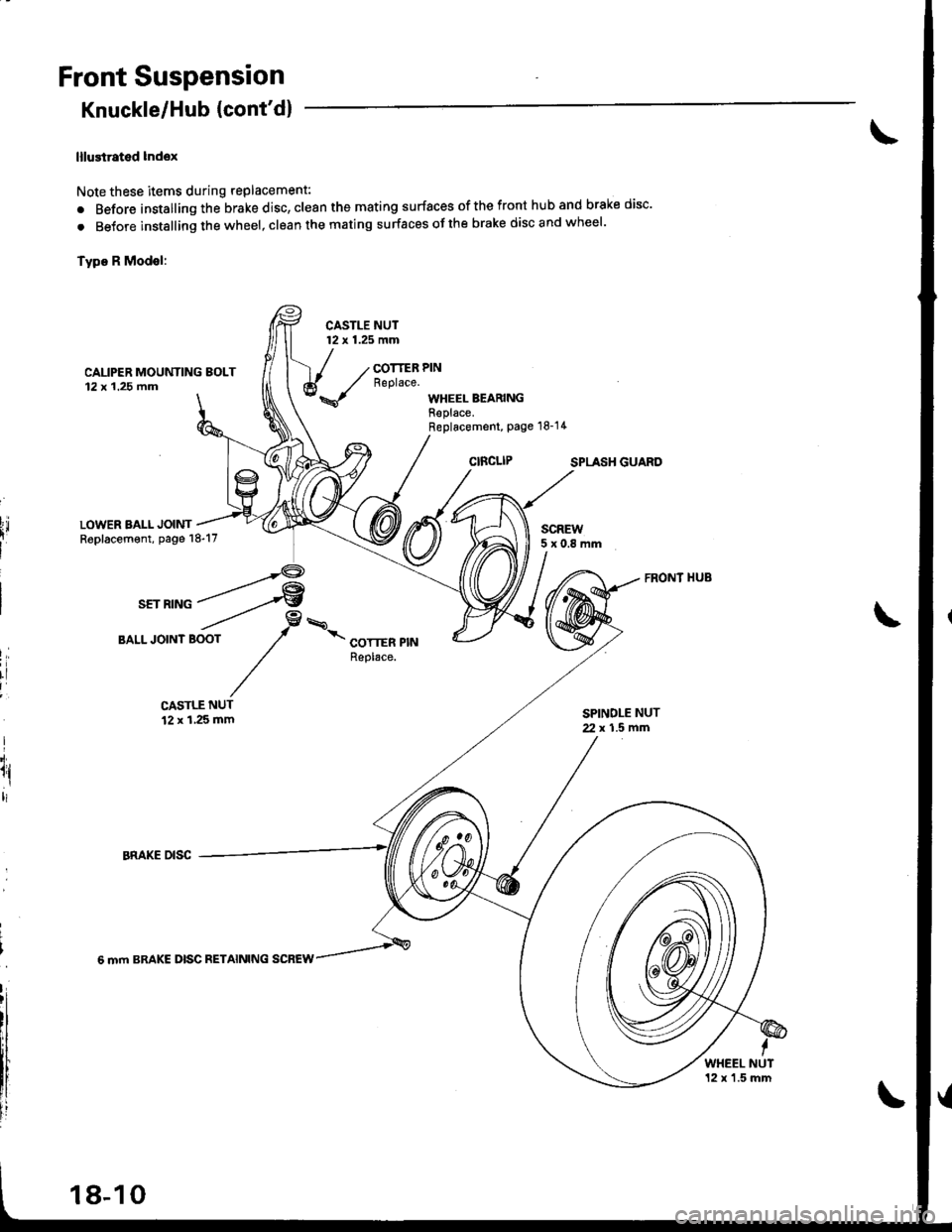
lllustrated lndox
Note these items during replacement:
. Before installing the brake disc, clean the mating surfaces of the front hub and brake disc'
. BeJore instslling the wheel, clean the mating surfaces ofthe brake disc and wheel'
Type R Modsl:
CASTLE NUT12 x 1.25 mm
CAUPER MOUNTING EOLT12x 1.25 fim
COTTER PINReplace.
WHEEL BEARINGReplace.Replacement, Page 18-14
SPLASH GUARO
LOWER BALL JOINTReplacement, page 18-17SCREW5x0.8mm
I,
rl
I
I'i.
1l,ltl
CASTLE NUT12 x 1,25 mmSPINDLE NUT2. x 1.5 mfi
6 mm BRAKE DISC RETAINING SCREW
WHEEL NUT12 x'1.5 mm
18-10
Page 721 of 1681
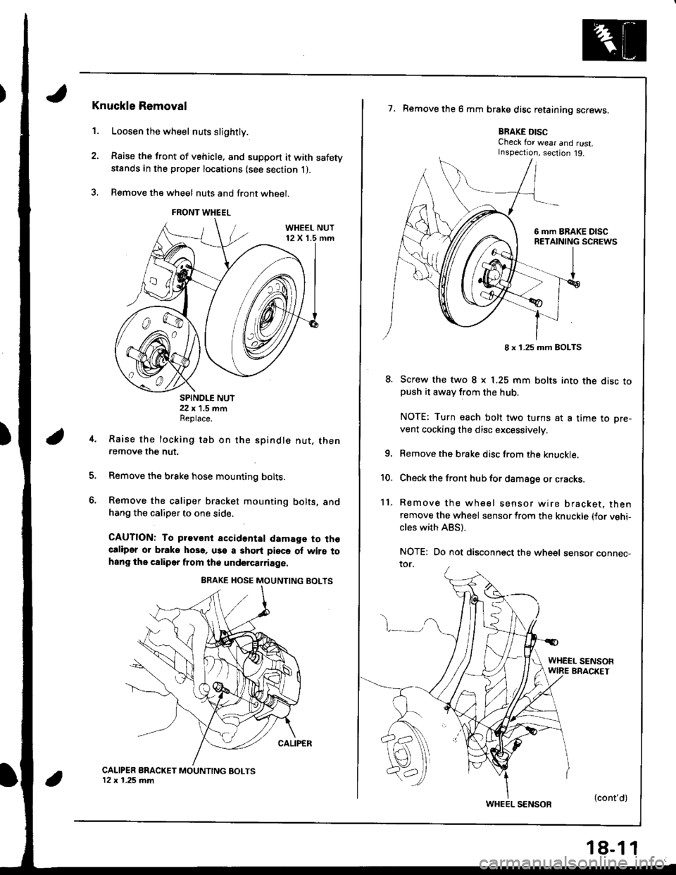
1.
Knuckle Removal
Loosen the wheel nuts slightly.
Raise the front of vehicle. and support it with safetystands in the proper locations {see section l ).
B€move the wheel nuts and front wheel.
SPINDLE NUT22 x 1.5 mmReplace.
Raise the locking tab on the
remove the nut.
spindle nut. then
Remove the brake hose mounting bolts.
Remove the caliper bracket mounting bolts, andhang the caliper to one side.
CAUTION: To pravant accidental damage to thgcaliper or braks hoso, use a shqrt piece of wirs tohsng the c8liper flom the undercarriage.
CALIPER BRACKET MOUNTING BOLTS12 x 1.25 mm
7, Remove the 6 mm brake disc retaining screws.
BRAKE DISCCheck for wear and rust.Inspection, section j9.
8. Screw the two I x L25 mm bolts into the disc topush it awav from the hub.
NOTE: Turn each bolt two turns at a time to pre-
vent cocking the disc excessively.
Remove the brake disc from the knuckle.
Check the front hub for damage or cracks.
Remove the wheel sensor wire bracket, thenremove the wheel sensor lrom the knuckle (for vehi-cles with ABS).
NOTE: Do not disconnect the wheel sensor connec-ror.
4.
6.
10.
11.
WHEEL SENSOFWIRE BRACKET
FRONT WHEEL
8 x 1.25 mm BOLTS
WHEEL SENSOR(cont'd)
Page 724 of 1681
Front Suspension
Knuckle/Hub (cont'd)
fl
l
Ili
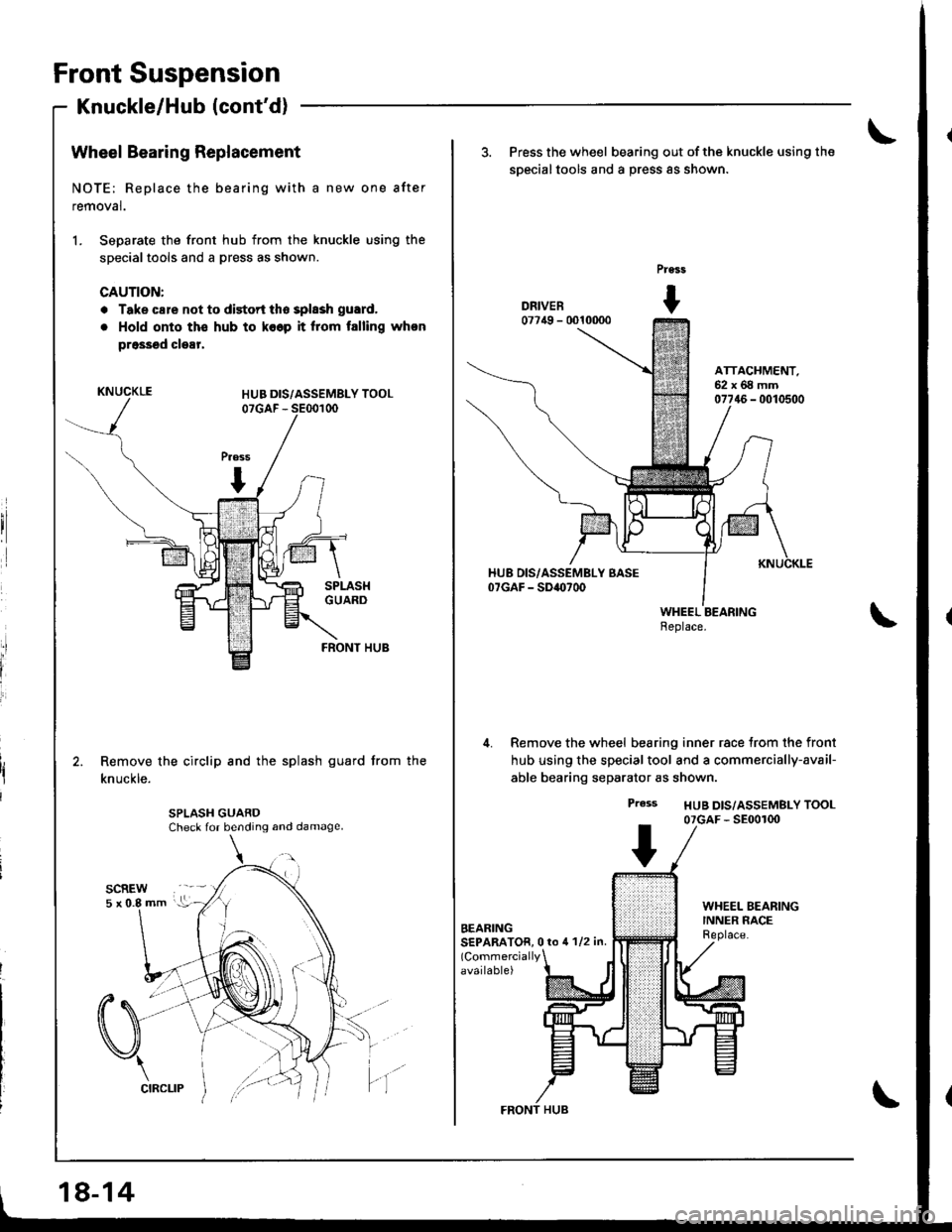
Wheel Bearing Replacement
NOTE; Replace the bearing with a new one after
removal.
1. Separate the front hub from the knuckle using the
specialtools and a press as shown.
CAUTION:
. Take cale not to distort tho splssh guard,
. Hold onto ths hub to ko6p it lrom talling whon
prossed clear,
KNUCKLE
FRONT HUB
Remove the circlip and the splash guard from the
knuckle.
SPLASH GUARDCheck for bending and damage
18-14
FRONT HUB
3. Press the wheel bearing out of the knuckle using the
soecialtools and a Dress as shown.
DRIVER07749 - 0010000
ATTACHMENT.52x68mm07746 - 0010500
Remove the wheel bearing inner race trom the front
hub using the specialtool and a commercially-avail-
able bearing separator as shown.
Press HUB D|S/ASSEMBLY TOOL07GAF - SE00100
BEARINGSEPARATOR, 0 ro 4 1/2 in.(Commercially
available)
Page 725 of 1681
\
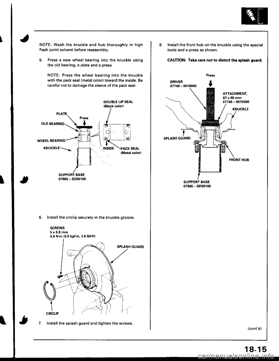
NOTE; Wash the knuckle and hub thoroughly in high
flash point solvent before reassembly.
5. Press a new wheel bearing into the knuckle using
the old bearing, a plate and a p.ess.
NOTE: Press the wheel bearing into the knuckle
with the pack seal (metal color) toward the inside. Be
careful not to damage the sleeve of the pack seal.
Installthe circlip securely in the knuckle groove.
SCREWS5x0.8mm4.9 N'm (0.5 kgf.m,3.5lbtftl
SPLASH GUARO
7. Install the splash guard and tighten the screws.
18-15
Installthe front hub on the knuckle using the special
tools and a press as shown,
CAUTION: Tako csro not to distort tho splash guard.
pre3s
DRIVER I0??a9 - 0010000 v
ATTACHMENT,62x68mm07746 - 00t0500
SPLASH GUARD
KNUCKLE
FRONT HUB
{cont'd)
Page 726 of 1681
Front Suspension
Knuckle/Hub (cont'd)
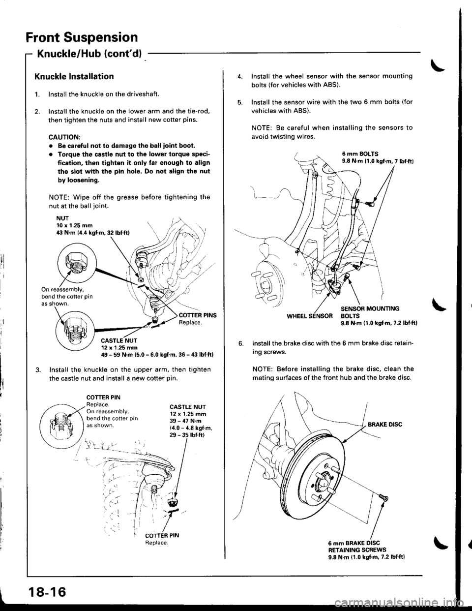
Knuckle lnstallation
1. lnstall the knuckle on the driveshaft.
2. lnstall the knuckle on the lower arm and the tie-rod,
then tighten the nuts and install new cotter pins.
CAUTION:
. Be carelul not to damage tho ball ioint boot.
a Torque the castls nut to the lowel torque spgci-
fication, then tight€n it only far enough to align
the slot with the pin hole. Do not align the nut
by loosening.
NOTE: Wipe off the grease before tightening the
nut at the ball joint.
NUT
ri
10 x 1.25 mm4il N.m (4.{ kgtm,32lbf.ftl
On reassembly,bend the cotter pin
as shown.
CASTLE NUT12 x 1 .25 mm49 - 59 N.m (5.0 - 6.0 kgf m, 36 -,|i| lbf ft)
3. Install the knuckle on the upper arm, then tighten
the castle nut and install a new cotter Din.
COTTER PINReplace.On reassembly,bend the cotter pin
CASTLE NUT12 x 1.25 mm39 - 47 N.m{4.0 - 4.8 kgf.m,29 - 3s rbr.ft)
;
, 'ar
COTTER PIN
18-16
4.Install the wheel sensor with the sensor mounting
bolts (tor vehicles with ABS).
lnstall the sensor wire with the two 5 mm bolts (for
vehicles with ABS).
NOTE: Be careful when installing the sensors to
avoid twisting wires.
6 mm BOLTS9.8 N.m 11.0 kgf.m,7 lbf.ftl
v_)
SENSOR MOUNTINGBOLTS9.8 N.m (1.0 kgf.m,7.2 lbl.ftl
6. lnstall the brake disc with the 6 mm brake disc retain-
Ing screws.
NOTE: Before installing the brake disc, clean the
mating surfaces of the front hub and the brake disc.
6 mm BRAKE DISCRETAINING SCREWS9.8 N.m 11.0 kgl.m, 7.2 lbf'ftl
Page 727 of 1681
Lower Ball Joint Replacement
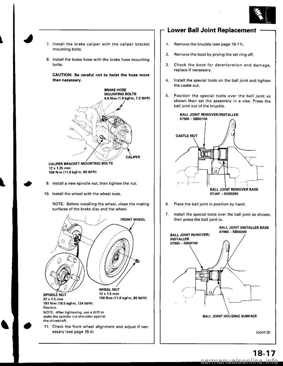
7.Install the brake caliper with the caliper bracket
mounting bolts.
Install the brake hose with the brake hose mounting
bolts.
CAUTION: Bo careful not to twist the hose more
than ngcsssary.
BRAKE HOSEMOUNNNG BOLTS
CALIPER BRACKET MOUNTING BOLTS
12 x 1.25 mm108 N.m (11.0 kgf m,80 lbtftl
\9.
10.
lnstall a new spindle nut, then tighten the nut.
Installthe wheel with the wheel nuts
NOTE: Before installing the wheel, clean the mating
surfaces of the brake disc and the wheel.
FRONT WHEEL
WHE€L NUT12 x 1.5 mm108 N.m {11.0 kgf.m,80 lbtft)22 x 1.5 mm181 N.m 118.5 kgt m, 134 lbl.ftlReplace.
NOTE: After tightening, us€ a drift tostake the spindle nut shoulder againstthe driveshaft.
11. Check the tront wheel alignment and adjust if nec-
essary (see page l8-4).
1.
2.
4.
5.
Remove the knuckle (see page 18-11).
Remove the boot by prying the set ring off.
Check the boot for deterioration and damage,
replace if necessary.
Install the special tools on the ball joint and tighten
the castle nut.
Position the special tools over the ball joint asshown then set the assembly in a vise. Press the
ball joint out of the knuckle.
07JAF - SH20200
Place the balljoint in position by hand.
Install the special tools over the ball joint as shown,
then press the ball joint in.
BALL JOINT INSTALLER BASE07965 - 5800200
6.
7.
(cont'd)
18-17
Page 728 of 1681
Front Suspension
Lower, Ball Joint Replacement
(confd)
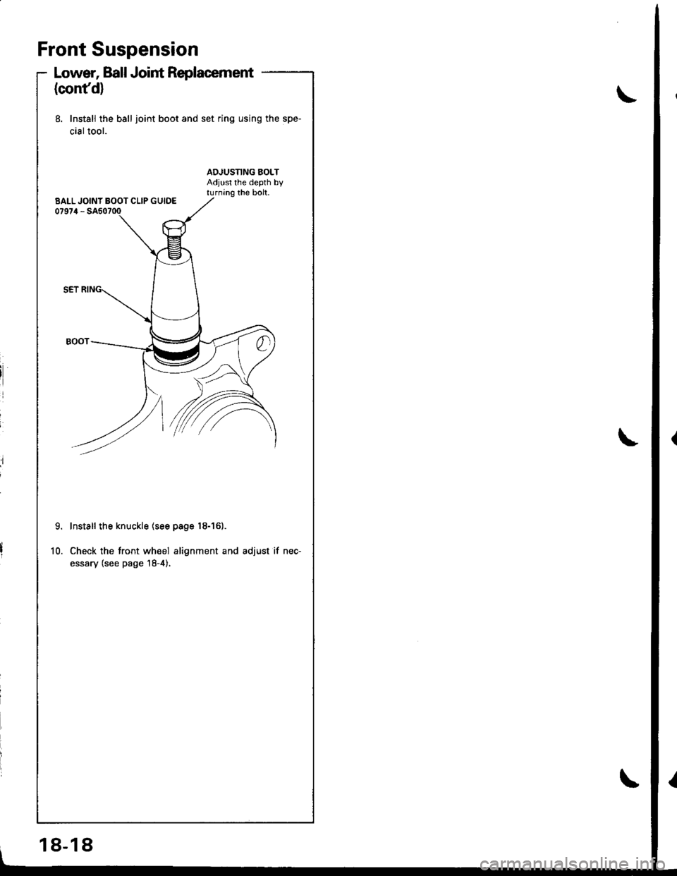
8. Install the ball joint boot and set ring using the spe-
cial tool.
9.
10.
Install the knuckle (see page 18-161.
Check the tront wheel alignment and adjust if nec-
essary (see page 18-4),
BALL JOINT BOOT CLIP GUIDE
18-18