lights HONDA INTEGRA 1998 4.G Repair Manual
[x] Cancel search | Manufacturer: HONDA, Model Year: 1998, Model line: INTEGRA, Model: HONDA INTEGRA 1998 4.GPages: 1681, PDF Size: 54.22 MB
Page 1250 of 1681
![HONDA INTEGRA 1998 4.G Repair Manual Circuit Diagram
UNDEB HOOD FUSUBELAY 8OX
N0.41 (100A) No.5l (l5A)
UNDER DASHFUSE/FELAY BOXCOMEINATIONLIGHT SWITCH
wHT ---{. rcr- RED/GRNV rclrrtor swror
WHT/BLK +WNTBLK/YEL
WHT/GRN
I GFNBLU GRIVBLU
-] HONDA INTEGRA 1998 4.G Repair Manual Circuit Diagram
UNDEB HOOD FUSUBELAY 8OX
N0.41 (100A) No.5l (l5A)
UNDER DASHFUSE/FELAY BOXCOMEINATIONLIGHT SWITCH
wHT ---{. rcr- RED/GRNV rclrrtor swror
WHT/BLK +WNTBLK/YEL
WHT/GRN
I GFNBLU GRIVBLU
-]](/img/13/6069/w960_6069-1249.png)
Circuit Diagram
UNDEB HOOD FUSUBELAY 8OX
N0.41 (100A) No.5l (l5A)
UNDER DASHFUSE/FELAY BOXCOMEINATIONLIGHT SWITCH
wHT ---{. rcr- RED/GRNV rclrrtor swror
WHT/BLK +WNTBLK/YEL
WHT/GRN
I GFNBLU GRIVBLU
-]JJ
IVVGRNIELU TRATLERI L|GHTINGI CONNECTOR
TRUN SIGNALswrTcHF (Not used)
GBN/ORN
GRNioRN-
GRNALU GRN/BLU
RED
tltl
rl
I
t
OASH LIGHTSBFIGHTNESSCONTROLLEH
*f --.f ,-+r*n"+
RN/YE
t
TBLK
GRN,YEL
tttol
I RE,
lo'8LK
8LK
I
G201G401
GFN/BLU
)
23-193
Page 1251 of 1681
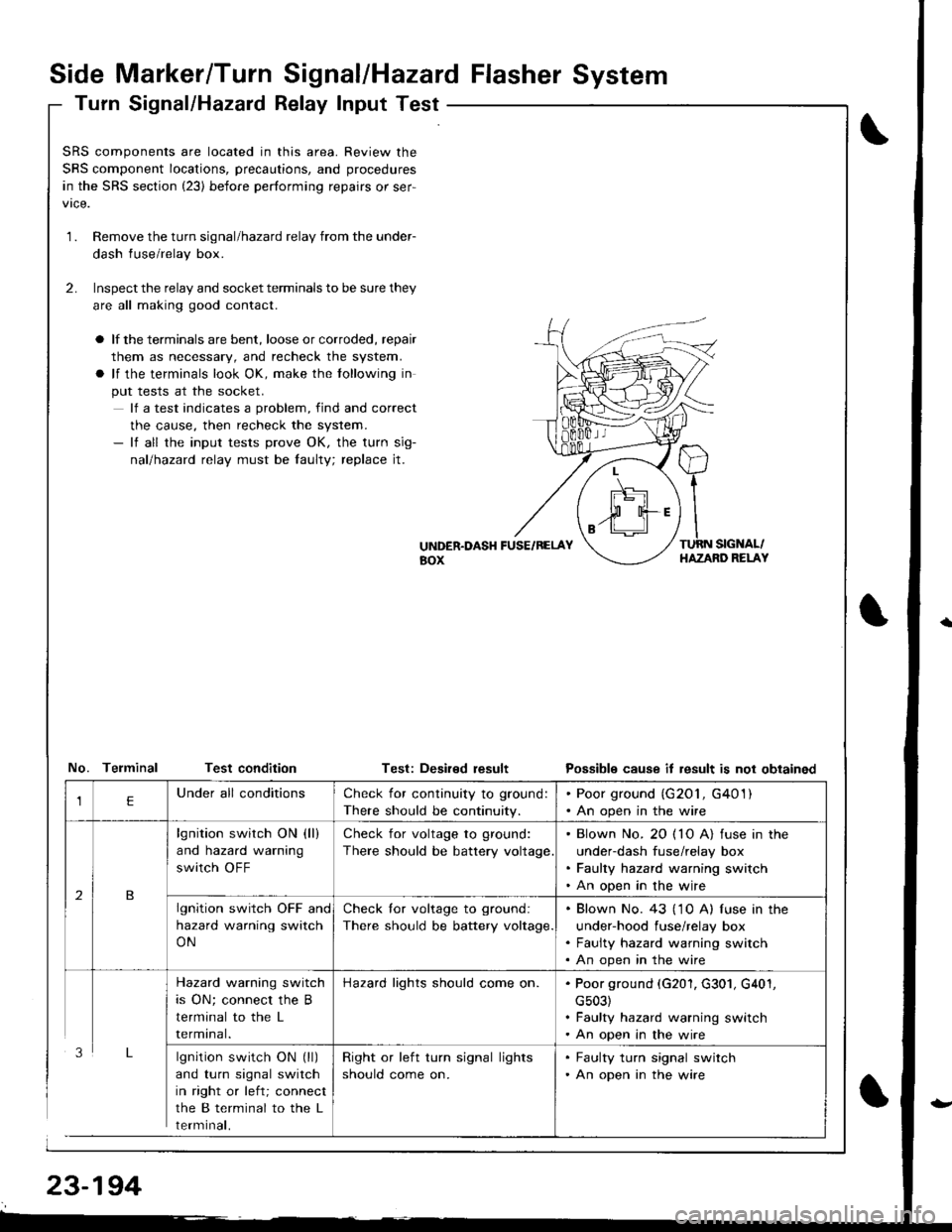
Side Marker/Turn Signal/Hazard Flasher System
Turn Signal/Hazatd Relay Input Test
\
t
SRS components are located in this area. Review the
SRS component locations, precautions, and procedures
in the SRS section (23) before performing repairs or ser-
1.Remove the turn signal/hazard relay from the under-
dash fuse/relay box.
Inspect the relay and socket terminals to be sure they
are all making good contact.
a lf the terminals are bent, loose or corroded, repair
them as necessary, and recheck the system.
a lf the terminals look OK, make the tollowing in
put tests at the socket.
lf a test indicates a problem, find and correct
the cause, then recheck the system.- lf all the input tests prove OK, the turn sig-
nallhazad relay must be faulty; replace jt.
2.
UiTDER.DASH FUSE/RELAYaox
TURN SIGNAL/HAZAND RELAY
No. Telminal Test conditionTest: Deaired resultPossible cause it result is not obtained
lgnition switch ON (ll)
and turn signal switch
in right or left; connect
the B terminal to the L
rermtnat,
Check for continuity to ground:
There should be continuity.
. Poor ground (G201, G401). An open in the wire
lgnition switch ON (ll)
and hazard warning
switch OFF
Check for voltage to ground:
There should be battery voltage
. Blown No. 20 ( 10 A) fuse in the
under-dash fuse/relay box. Faulty hazard warning switch. An open in the wire
lgnition switch OFF and
hazard warning switch
ON
Check lor voltage to ground:
There should be battery voltage.
. Blown No. 43 ('1 0 A) f use in the
under-hood fuse/relay box. Faulty hazard warning switch. An open in the wire
Hazard warning switch
is ON; connect the B
terminal to the L
rermtnat.
Hazard lights should come on.. Poor ground (G201, G301, G401,
cs03). Faulty hazard warning switch. An open in the wire
Right or left turn signal lights
should come on.
. Faulty turn signal switch. An open in the wire
Page 1257 of 1681
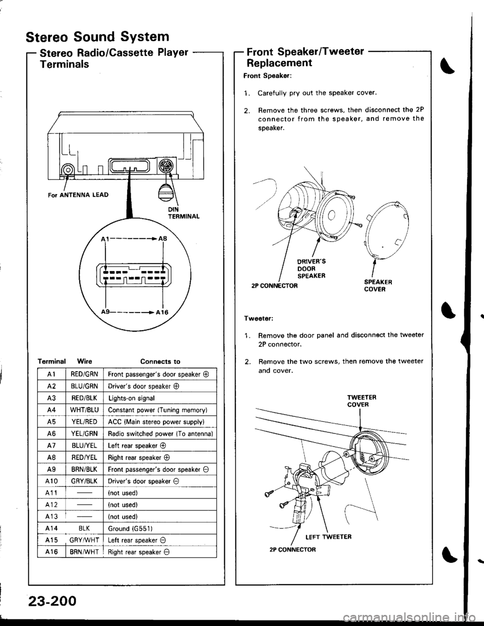
Stereo
Stereo
Sound System
Radio/Cassette PlayerFrontSpeaker/Tweeter
Replacement
Front Sp€aker:
'1. Carefully pry out the speaker cover.
2. Remove the three screws, then disconnect the 2P
connector from the speaker, and remove the
speaKer.
2P CONNECTOR
Tweoter:
1. Remove the door panel and disconn€ct the tweeter
2P connector.
2. Remove the two screws, then remove the tweeter
ano cover.
A
//1
\7
)-ISPEAKERCOVER
2P CONNECTOR
Terminals
T€rminalWireConnecta to
\
FoT ANTENNA LEAD
oIttFRMINAL
a9- -- -------> A 16
AIRED/GRNFront passenge.'s door speaker @
A2BLU/GRNDriver's door speaker O
A3RED/BLKLights-on signal
A4WHT/BtUConstant power (Tuning memory)
A5YEL/REDACC {Main stereo power supply)
A6YEL/GRNRadio switched power 1To antenna)
A7BLU/YELLeft rear speaker @
A8RED/YELRight rear speaker @
A9BRNi BLKFront passenger's door speaker O
A10GRY/BLKDriver's door speaker O
A11(not used)
{not used)
A13(not used)
A14 BLKGround {G551)
A15 GRY,ryVHTLeft rear speaker O
A168RN AVH TRight rear speaker O
23-200
Page 1263 of 1681
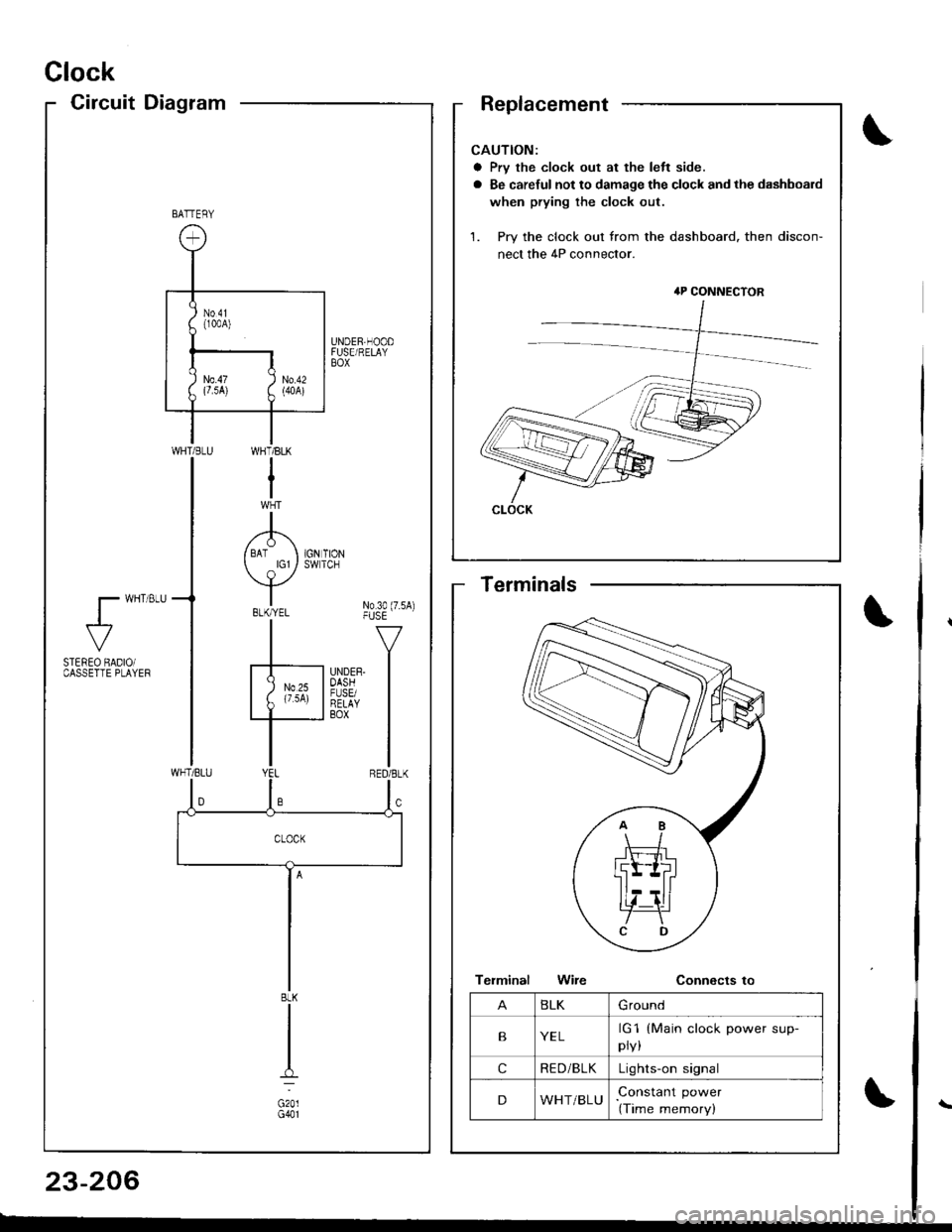
Clock
CircuitDiagram
CAUTION:
a Prv the clock out at the left side.
a Be careful not to damage the clock and the dashboard
when prying the clock out.
1. Pry the clock out from the dashboard. then discon-
nect the 4P connector.
4P CONNECTOR
CLOCK
BATTERY
UNDER,HOODFUSE/RELAYBOX
WI-]T/BLK
I
A/ BAT I 1GN TION
Y*"t No3o(7.sA)-|" -v
F'nrrn l
I
WHT/BLU
l- wHT 8LU
al-
STEREO BADIOiCASSETTE PLAYEF
BLK
G201G401
BLKGround
BYELrG1
pry,
(Main clock power sup-
cRE D/BLKLights-on signal
DWHT/BLUConstant power
(Time memory)
Terminals
23-206
Page 1269 of 1681
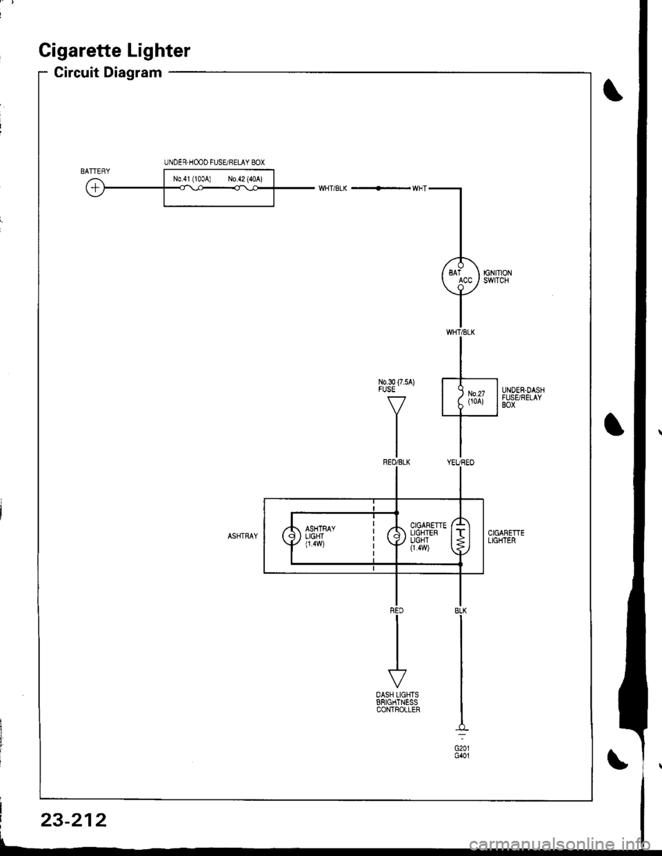
Gigarette Lighter
Circuit Diagram
UNDER.HOOD FUSURELAY 8OX
3o{75A) J-
Y
Lit*is***/
I
r'
OASH LIGHTSERIGHTNESSCONTFOLLER
BLK
G201G401
23-212
Page 1272 of 1681
![HONDA INTEGRA 1998 4.G Repair Manual Circuit Diagram
REARwtNDowDEFOGGERSWITCH
BLK
IIJ
DASH LIGHTSBR CHTNESSCONTROLLER
CN TIONswrTcH
/ 8AT \
T ",7-l
II
II
WNT/BLK + WHT
REARWiNDOWDEFOGGER
BtK/GRN
--lELKGRN BLI(RED
1A
T L-]
ll
tl
tl
tl-l
U HONDA INTEGRA 1998 4.G Repair Manual Circuit Diagram
REARwtNDowDEFOGGERSWITCH
BLK
IIJ
DASH LIGHTSBR CHTNESSCONTROLLER
CN TIONswrTcH
/ 8AT \
T ",7-l
II
II
WNT/BLK + WHT
REARWiNDOWDEFOGGER
BtK/GRN
--lELKGRN BLI(RED
1A
T L-]
ll
tl
tl
tl-l
U](/img/13/6069/w960_6069-1271.png)
Circuit Diagram
REARwtNDowDEFOGGERSWITCH
BLK
IIJ
DASH LIGHTSBR CHTNESSCONTROLLER
CN TIONswrTcH
/ 8AT \
T ",7-l
II
II
WNT/BLK + WHT
REARWiNDOWDEFOGGER
BtK/GRN
--lELKGRN BLI(RED
1A
T L-]
ll
tl
tl
tl-l
UNDEF HOOD FUSE/RELAY BOX
No41 (100A) N0.42 (40A)
G201G401G201G40lHatchback:G771Sedan iG503I
23-215
Page 1347 of 1681
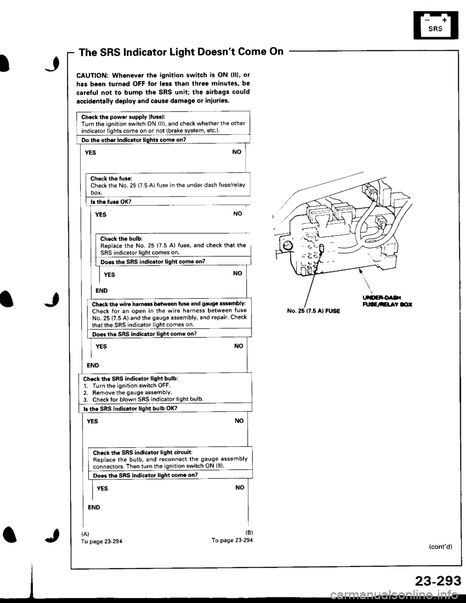
The SRS Indicator Light Doesnt Come On
CAUTION: Whenever the ignition switch is ON (lll, ol
has been turned OFF tor lsss than three minutes. be
careful not to bump the SRS unit; the airbags could
accidentslly deploy and cause damage or iniuries.
Chcck tho power supply lfuso):Turn the ignition switch ON (ll), and check whether the other
indicator lights come on or not (brake system, etc.).
Do tho oth6J indicator ligh$ come on?
NO'ES
Check ths tuse:Check the No. 25 (7.5 Ai fuse in the under dash fuse/relayho!
ls th. tu.o OK?
YESNO
Chsck the bulb:Replace the No. 25 17.5 A) fuse, and check that the
SRS indicator light comes on.
Doos tho SRS indic.lor light como on?
YES
END
Ch.ck th6 wir€ ham€ls b€twoen fu3e snd gauge .3sembly:
Check for an open in the wire harness belween tuse
No. 25 (7.5 A) and the gauge sssembly, and repair. Check
that the sRS indicator light comes on.
Doo3 the SRS indicator light come on?
YES
NO
NO
END
Ch6ck tho SRS indicator light bulb:
1. Turn the ignition switch OFF.2. Remove the gauge assemblY3. Check tor blown SRS indicator light bulb.
b tho sRs indicrlor light bulb oK?
YESNO
Check tho SRS indicator ligln circuit:ReDlace the bulb, and reconnect the gauge assembly
connectors. Then turn the ignition switch ON (ll).
Do.s tho SRS indicrtor light comG on?
I vrs NoII
END
No. 25 lt.5 Al FUSE
{A)fo page 23-294
(B)
10 page 23-294(cont'd)
Page 1383 of 1681
).1
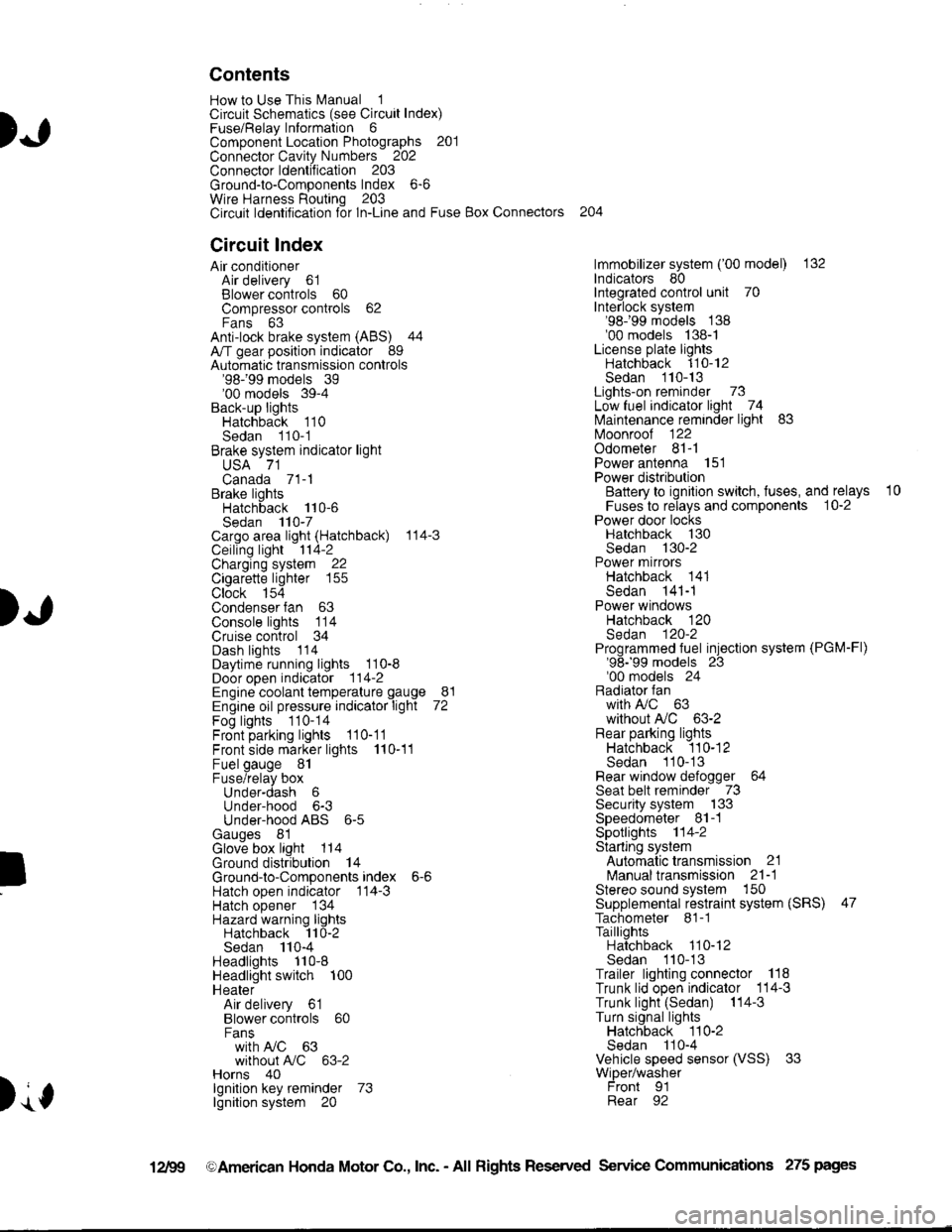
Contents
How to Use This l\.4anual 1Circuit Schematics (see Circuit Index)Fuse/Relaylnformation 6ComponentLocation Photographs 201
Connector Cavity Numbers 202Connectorldentification 203
Ground-to-Components Index 6-6Wire Harness Routing 203Circuit ldentification lor ln-Line and Fuse Box Connectors
Circuit Index
Air conditionerAir delivery 61Blower controls 60Compressor controls 62Fans 63Anti-lock brake system (ABS) 44A/T gear position indicator 89Automatic transmission controls'98199 models 39'00 models 39-4Back-up lightsHatchback 110Sedan 110- 1Brake system indicator light
USA 71Canada 71-1Brake lightsHatchback 110-6Sedan 110-7Cargo area light (Hatchback) 114-3Ceiling light 114-2Charging system 22Cigarette lighter 155
Clock 154Condenser fan 63Console lights 114Cruise control 34Dash lights 1 14Daytime running lights 110-8Door open indicator 114-2Engine coolant temperature gauge 81Engine oil pressure indicator light 72Fog lights 110-14Front parking lights 110-11Front side marker lights 110-11Fuel gauge 81Fuse/relay boxUnder-dash 6Under-hood 6-3Under-hood ABS 6-5Gauges 81Glove box light 114Ground distribution 14Ground-to-Componentsindex 6-6Hatch open indicator '114-3
Hatch opener '134
Hazard warning lightsHatchback 'l l0-2Sedan 110-4Headlights 1'10-8Headlight switch 100HeaterAir delivery 61Blower controls 60Fanswith A,/C 63without A,/C 63-2Horns 40lgnilion key reminder 73lgnition system 20
204
lmmobilizer system ('00 model) 132lndicators 80Integrated control unit 70Interlock system'98199 models 138'00 models 138-1License plate lightsHatchback 110-12Sedan 110-13Lights-on reminder 73Low fuel indicator light 74l\,4aintenance reminder light 83l\iloonroof 122Odometer 81-1Power antenna 151Power distributionBattery to ignilion switch, fuses, and relays
Fuses to relays and components 10-2Power door locksHatchback '130
Sedan 130-2Power mirrorsHatchback 141Sedan 141-1Power windowsHatchback 120Sedan 120-2Programmed fuel injection system (PGM-Fl)'98199 models 23'00 models 24Radiator fanwith tuC 63without A,/C 63-2Rear parking lightsHatchback 110-12Sedan 110- 13Rear window defogger 64Seat belt reminder 73Security system 133Speedometer Il-1Spotlights 114-2Starting syslemAutomalictransmission 21l\.4anualtransmission 21-1Stereo sound system 150Supplemental restraint system (SRS) 47Tachometer 81- 1TaillightsHatchback 110-12Sedan 110-13Trailer lighting conneclor 118Trunk lid open indicator 114-3Trunk light (Sedan) 114-3Turn signal lightsHatchback 110-2Sedan 110-4Vehicle speed sensor (VSS) 33Wiper/washerFront 91Rear 92
10
).1
I
Xr
12Fg oAmerican Honda Motor Co., Inc. - All Rights Reserved Service Communications 275 pages
Page 1388 of 1681
)a
)a
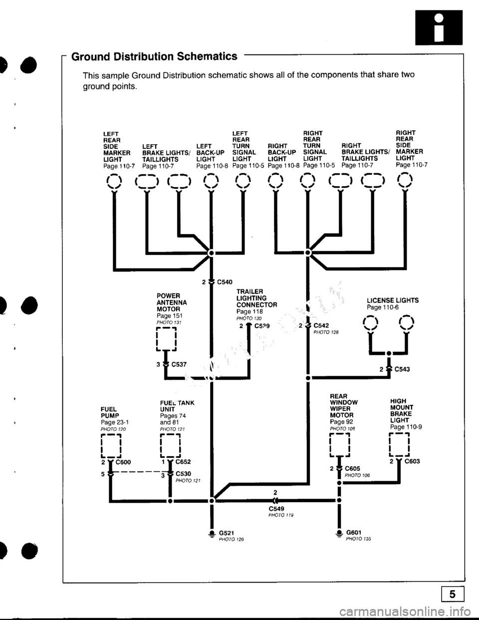
'ouno ulslnoulron Scnemarlcs -
This samDle Ground Distribution schematic shows all of the components thal share two
ground points.
LEFT RIGHT RIGHTREAR REAR REARLEFT LEFT TURN RTGHT TURN RIGHT SIDEBRAKE LIGHTS/ BACK-UP SIGNAL BACK-UP SIGNAL BRAKE LIGHTS/ MARKER
TAILLTGHTS LIGHT LIGHT LIGHT LIGHT TAILLIGHTS LIGHT
Page110-7 Page110-8 Page110-5 Page110-8 Page110'5 Page110-7 Page110-7
r--r r--t t- t-l t-t ,-t r--r r--t r-\t*-r r--r \./ \/ \./ \/ \/
I LICENSE LIGHTS
I Page 110'6
l"uo, O O
l*"''* L.J
!-.1**
FUELPUMPPage 23-1
lltl
LEFTREARstoEMARKERLIGHTPage 110-7
POWERANTENNAMOTORPage 151
tlll
:E_,
a-al
JL
c549
t\
HIGHMOUNTBRAKELIGHTPage 110-9
ttll
REARwtNDowWIPERMOTORPage 92
tlll
iIn*
a-
Ira
T!. G601
FUEL TANKUNITPages 74and 81
tltl
1 Y C652
irg c530- | puoro tzt
I
106
T+ Gs21
c603
Ground DistributiSchematics
E
)o
Page 1390 of 1681
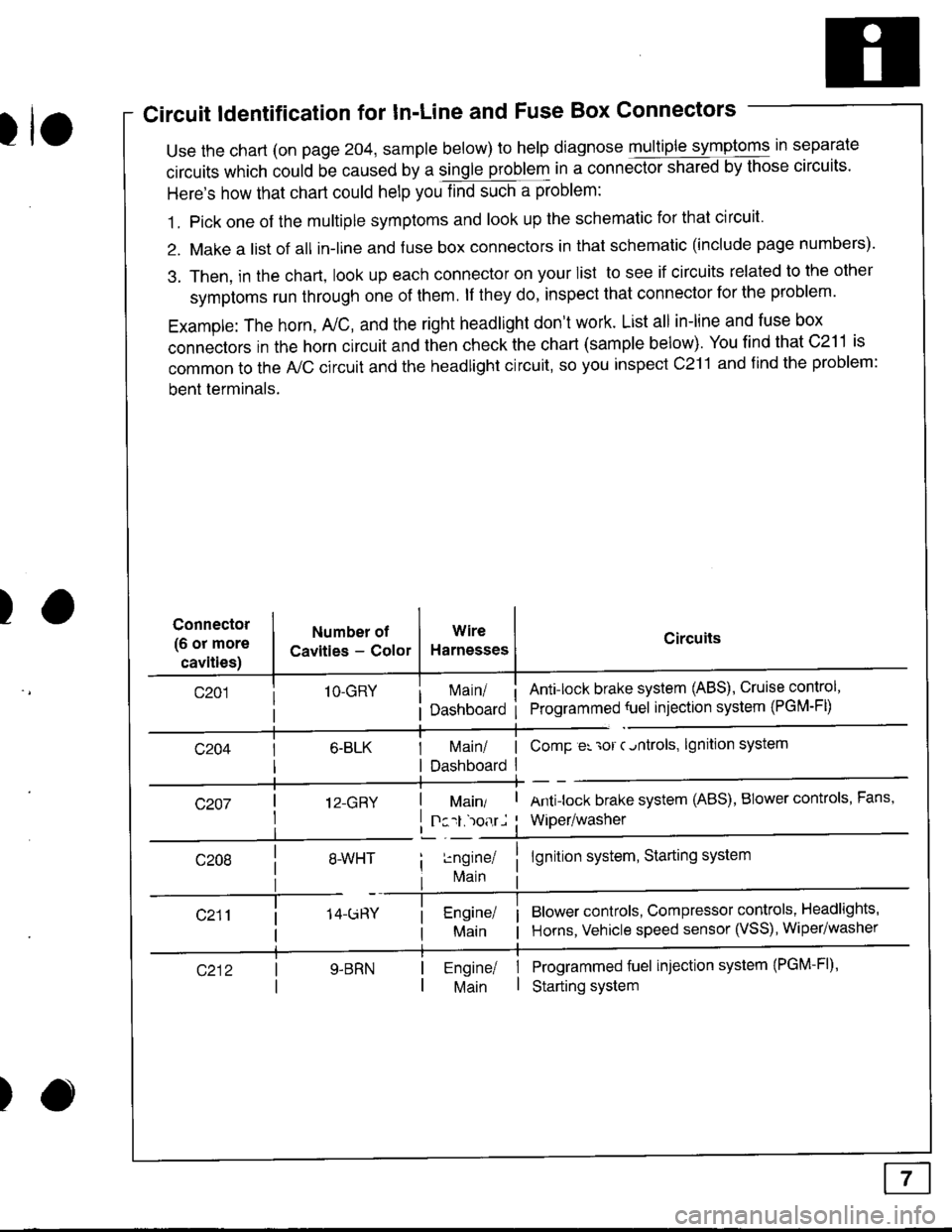
Circuit ldentification for In'Line and Fuse Box Connectors
tuse the chart (on page 204, sample below) to help diagnose multiple symptoms in separate
circuits which could be caused by a single problem in a connect,oishared by those circuits'
Here's how that chart could help you find such a problem:
1. Pick one of the multiple symptoms and look up the schematic for that circuit'
2. Make a list of all in-lrne and fuse box connectors in that schematic (include page numbers).
3. Then, in the chart, look up each connector on your list to see if circuits related to the other
symptoms run through one of them. lf they do, inspect that connector for the problem.
Example: The horn, A,/C, and the right headlight don't work. List all in-line and fuse box
connectors in the horn circuit and then check the chart (sample below). You find that C211 is
common to the A,/C circuit and the headlight circuit, so you inspect c211 and find the problem:
bent terminals.
)Connector
(6 or more
cavities)
Numbel of
Cavities - Color
1O-GRY
I 12-GRY
I
Wire
Harnesses
I Main/ | ComP er 'ror c.ntrols,
I Dashboard I
Circuits
Ant!lock brake system (ABS), Cruise control,
Programmed {uel injection system (PGM-FD
!ngrnei
lvlain
lgnition system
Antilock brake system (ABS), BIower controls, Fans,
Wiper/washer
lgnition system, Starting system
Blower controls, Compressor controls, Headlights'
Horns, Vehicle speed sensor (VSS), Wiper/washer
Programmed fuel injection system (PGM-Fl)'
Starting system
Engine/ |Main I
)