turn signal HONDA INTEGRA 1998 4.G Repair Manual
[x] Cancel search | Manufacturer: HONDA, Model Year: 1998, Model line: INTEGRA, Model: HONDA INTEGRA 1998 4.GPages: 1681, PDF Size: 54.22 MB
Page 1507 of 1681
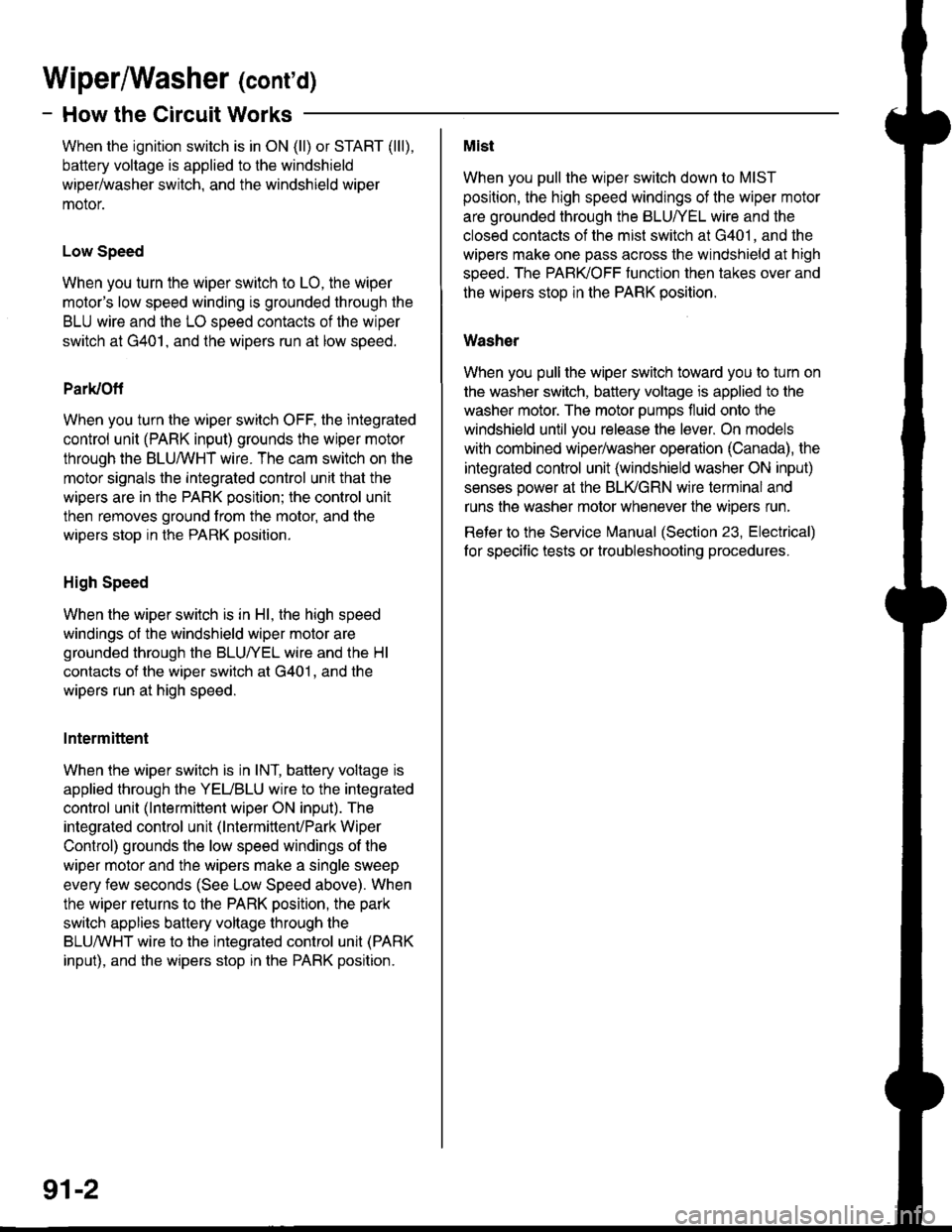
Wiperffasher (contd)
- How the Circuit Works
When the ignition switch is in ON (ll) or START (lll),
battery voltage is applied to lhe windshield
wiper/washer switch, and the windshield wiper
motor.
Low Speed
When you turn the wiper switch to LO, the wiper
motor's low speed winding is grounded through the
BLU wire and the LO speed contacts of the wiper
switch at G401, and the wipers run at low speed.
ParUOfi
When you turn the wiper switch OFF, the integrated
control unit (PARK input) grounds the wiper motor
through the BLUMHT wire. The cam switch on the
motor signals the integrated control unit that the
wipers are in the PARK position; the control unit
then removes ground from the motor, and the
wipers stop in the PARK position.
High Speed
When the wiper switch is in Hl, the high speed
windings ol the windshield wiper motor are
grounded through the BLUI/EL wire and the Hl
contacts of the wiper switch at G401 , and the
wipers run at high speed.
Intermittent
When the wiper switch is in lNT, battery voltage is
applied through the YEUBLU wire to the integrated
control unit (lntermittent wiper ON input). The
integrated control unit (lntermittenvPark Wiper
Control) grounds the low speed windings of the
wiper motor and the wipers make a single sweep
every few seconds (See Low Speed above). When
the wiper returns to the PARK position, the park
switch applies battery voltage through the
BLUMHT wire to the integrated control unit (PARK
input), and the wipers stop in the PARK position.
91-2
Mist
When you pull the wiper switch down to MIST
position, the high speed windings of the wiper motor
are grounded through the BLU//EL wire and the
closed contacts of the mist switch at G401, and the
wipers make one pass across the windshield at high
speed. The PABKOFF tunction then takes over and
the wrpers stop in the PARK position.
Washer
When you pull the wiper switch toward you to turn on
the washer switch, battery voltage is applied to the
washer motor. The motor pumps fluid onto the
windshield until you release the lever. On models
with combined wiper/washer operation (Canada), the
integrated control unit (windshield washer ON input)
senses power al the BLI(GRN wire terminal and
runs the washer motor whenever the wioers run.
Reter to the Service irlanual (Section 23, Electrical)
for specific tests or troubleshooting procedures.
Page 1511 of 1681
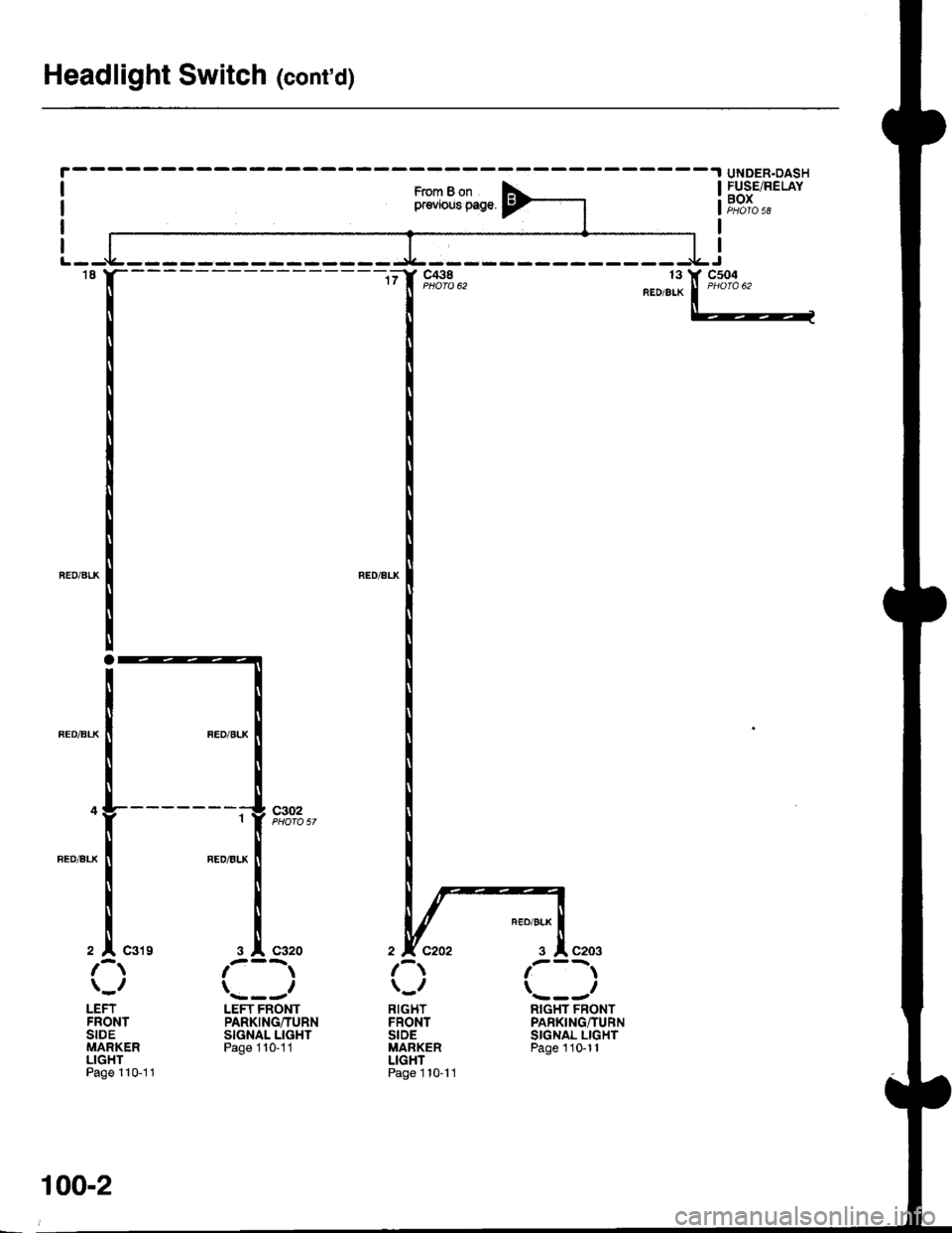
Headlight Switch (cont'd)
-.I UNDER.OASH
From B onpr€vious page.
FUSE/RELAYBOX
't8
2 |' C319
c302
LEFTFRONTSIDEMARKERLIGHTPage 110-11
3 l' C320
LEFT FRONTPARKING/TURNSIGNAL LIGHTPage 1 10-11
RIGHTFRONTSIDEMARKERLIGHTPage 1 10- l1
RIGHT FRONTPARKING/TURNSIGNAL LIGHTPage 110-11
100-2
Page 1515 of 1681
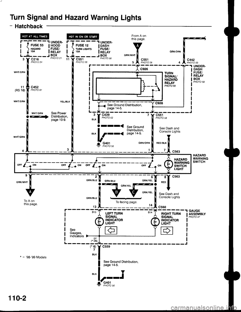
Turn Signal and Hazard Warning Lights
From A onrnts page.
v
i"""*i'.!,
F;%,,r
f'T----.lUNDER-
I r FUSE 12 | DASH
i )t8I"'**. i5Eii{,LIL----JBOX
r
I
I
-f,
)I
I"3Y(
- Hatchback
FUSE 53}IAZABO10t
c452
'tl Y C551
.I UNDER.
I HOOD
: FUSE/I RELAYJ BOx
See PowerDistribution,page 10-9.
UNDER-DASHFUSE/RELAYBOX
HAZARDWARNINGSWITCH
11(RS 10)
See Ground Distribution,page 14-5.
WHT/GRN
WHT/GRN
WHT/GNN
See Dash andConsole Lights
TRED/BrK
I
--U cssg
See GroundDistribution,page 14-5.
"l^f :,*+:..
Orrr<
*^ l/r--<
-r- 91q1--GBN/OBN
1
GAUGEASSEMBLY
---";;il-::r "*.
!F[ ,**t,**
pase. t
-----11I csoo
@i{FH'"'
----"-""-".i]ffi;---
! Ell cnn '
IV:=..=--l 'G
.,g l_______----.----,,1F
LEFT TUFN
rA I'l3i$'o'
\f,/t LIGHr
see Y fHGauges, I I
-lInorcarors >------+-
RIGHT TURNSIGNALI}IDICATORUGHT
ToAonrnrs page_
* = '98-'99 l,4odels
HAZARDWARNII{GswtTcHLIGHT
110-2
Page 1516 of 1681
c434
>-ra
BLK
COMBINATIONLIGHTswtTcHl!rnSignalSwllch
L-
From B onfacing page.
v
iGRN/BLU I GFN/BLU
. Jl "",%%* u
'T
"r""* I
______e-t
"ih::-i'
I
I
t6
GFN/BLU
GFN/BLt'
1
H
I::
[ff
c320
ALK
A
c504
Used) 15
GRN/EIU
CRN/ALU
SeeParkingLights cFN/BLU
3
---.I UNDER-DASHI FUSE/RELAY
iF,oJ","
c504 10PhoTa 62
GFN/YELo"nrtaa
I
----+
GBN/BLU ;T:]* I
c516(ln-line connector;may not be presentin all cars.)
a
[,*
RED/BLK See
,[r",...'---
/-l'_' LEFT FBONTT lo q T PARKING/TURN
\:9./ srcNAL LrcHr
BLK
See GroundDistribution,page 1+3.
Y
T
/A lerr neanI b I TURN SIGNAL
v/ LIGHT
Y
"t"
I see croundOr-( Dist.ibution,
rA\+,1?il'qEll r ,'/ LrGHr
*"r
/-m BtcHT FRONTrlo <2{ I PARKING/TURN
\:-S-,/ srcNAL LlcHr
c203
BLK-
See GroundDistribtdion,page 14-2.
I
L__J'+: G201
BLK
c523
L-_J+.= G30t
From C ontacrng Page.
v
tGFNffEL I
9:"4,2," t Jl "",u"%*
110-3
Page 1517 of 1681
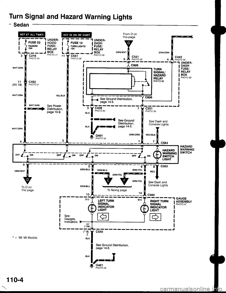
Turn Signal and Hazard Warning Lights
From D onthis page.
v
i"""*l'.!,
F,*%.,r
- Sedan
11 Y C551GRN/OFN
4
rT----'l UNDER.I I FUSE 12 | DASH
i ) TH"uo"'. i[EiE{,L j.___-J BOXc216
c452
WHT/GRN
TURNSIGNAUHAZANDRELAY
UNOER.DASHFUSE/RELAYBOX
HAZARDWARNINGswtTcH
11(BS 10)
See Ground Distribution,page 1+5.
YEUBLK
See PowerDistribution,page 1G9.
r andLights
' c551
Ser
BED/8
i5't)IQ 5A
See Dash aConsole LiC
Ioret.x ll
lt.-1 c:
BED/8LK
7
GFX/OBN
'|
See GroundDishibltion,page 1+5.
"l-1m*"
arrr<
*.L_;,,-'
---";;|tr--sf cs63
F[ ***,,,*
page i
.-----11I cr"o
RIGHT TURN
@ffiH*
IH
----";";.i-tr-;;--
! Elt o"n '
lv:;..=--j
-G
rs l_______-------:-'1F
LEFT TURN
@il!H'*
3:",n"", i|€]Indicators )--_-_-{___
-"-u
ToDonrnrs page.
GAUGEASSEMBLY
* = 98-'99 l\4odels
HAZANOWARNINliswtTcHUGHT
110-4
Page 1523 of 1681
Headlights (cont'd)
- How the Circuit Works
Low Beam OperationRefer to the Service Manual (Section 23, Electrical)
for specific tests or troubleshooting procedures.
With the headlight switch in HEAD and the dimmer
switch in LO, current flows through the headlight
switch, fuse 21 , tuse 22, and the low beam
filaments to ground, and the low beams come on.
tligh Beam Operation
With the headlight switch in HEAD and the dimmer
switch in Hl, current flows through the headlight
switch, dimmer/passing switch, fuses 4, 5, 21, and
22, and the low and high beam filaments to ground,
and the low and high beams come on.
Current also tlows through the high beam indicator
light to ground. The high beam indicator comes on
to remind the driver that the high beams are on.
Flash operation
The flash feature works with the headlight switch in
OFF, PARK, or HEAD (low beams). When you
move the flash-to-pass switch to ON, current flows
through the switch, fuses 4 and 5, and the high
beam filaments to ground, and the high beams
flash. The high beam indicator also flashes during
the flash oDeration. The flash function has no effect
it the high beams are already on.
Daytime Running Lights Day Operation
When you turn the ignition to ON (ll) with the
parking brake released, the daytime running lights
control unit supplies battery voltage at the
WHT/RED wire. This voltage is applied to the high
beam headlights through the daytime running lights
resistor. Each high beam headlight receives less
than battery voltage causing them to come on al
reduced brightness.
lf the parking brake is set, a ground signal is applied
to the daytime running lights control unit at the
RED/GRN wire. It the parking brake is set when you
first turn the ignition switch to ON (ll), the high beam
headlights will remain off until you release the
parking brake. Once the high beam headlights are
in day mode, setting the parking brake will not
cause the headlights to turn off . When low or high
beam operation is requested, baftery voltage trom
the headlight switch is applied to the daytime
running light control unit via the RED/vVHT wire.
The daytime running light control unit then
discontinues the daytime running light mode.
1 10-10
Page 1524 of 1681
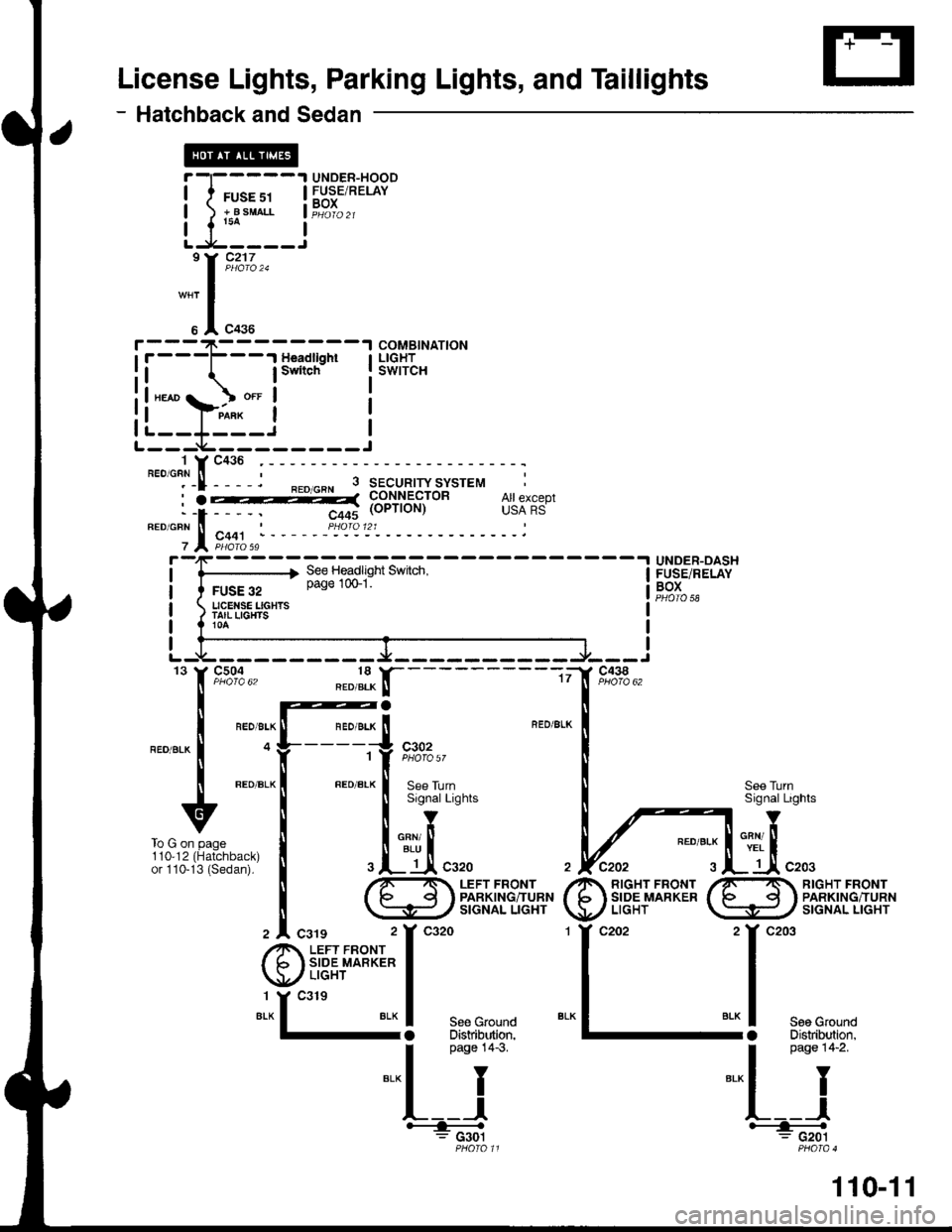
License Lights, Parking Lights, and Taillights
- Hatchback and Sedan
UNOEB-HOODFUSE/RELAYBOX
COMBINATIONLIGHTSWITCH
UNDER-OASHFUSE/RELAYBOXPHOTO 58
RED/gLK
I
@il*+'m;
c438
f, n%"' "."f-tr'-----
| @a
I "'. -, " tl "'. ., " i BED/il ---'l --'r
I o y_____ii ,%%,,
t ".o ".* | ".o ".* ! a"" ,r,nlt ---- tl ----t :]
u ! ls'snarlishts
,irr*^ . I inl
i3?iH;ll' I .l- tAcszo
il ^/r'- . LEFr FRONr
i \s#/3m,rlti#'#
z |. csrg 2Y ca2o
@i"fft**t-;
"*13!
***
I
Pase 14-3
=-l I
L__l__=;*;
See TurnSignal Lights
env ltYEL I
_ Jl c203110,12or 110-RIGHT FRONTPARKING/TURNSIGNAL LIGHT
il-,;;-l
Llr_i,193;]"*
"*r I
u I "o.u
i.--+-----.-r""*r;-l
il lswitch Ill"*or o.t I
!|"*"};^i_*'i I
rl__r_ _i IL--- i---------J
To G on page
110-11
Page 1533 of 1681
![HONDA INTEGRA 1998 4.G Repair Manual i-1:
!._ll
""*"t-[:
::il
--1 UNDER- TT----1 UNDER-DASHsE s3 I HOOD I f FUSE 12 | FUSE/RELAY^Bo
|FE:F{, i },8In""" iF"?T".,__.1 BOX U-:L-----r
]3," f, rt,i%., FromAon
te Power t
tnrs Pase
:i:it8: HONDA INTEGRA 1998 4.G Repair Manual i-1:
!._ll
""*"t-[:
::il
--1 UNDER- TT----1 UNDER-DASHsE s3 I HOOD I f FUSE 12 | FUSE/RELAY^Bo
|FE:F{, i },8In""" iF"?T".,__.1 BOX U-:L-----r
]3," f, rt,i%., FromAon
te Power t
tnrs Pase
:i:it8:](/img/13/6069/w960_6069-1532.png)
i-1:
!._ll
""*"t-[:
::il
--1 UNDER- TT----1 UNDER-DASHsE s3 I HOOD I f FUSE 12 | FUSE/RELAY^Bo
|FE:F{, i },'8In'""'" iF"?T".,__.1 BOX U-:L-----r
]3," f, rt,i%., FromAon
te Power t
tnrs Pase
:i:it8: vere'�xl Y
I ..[
- - - - - - rJ.- - - - --"]:l-tr "*.
FIOM E ONrnrs page.
v
ll cougrlrrrolcRNioFN I LTGHT
, Jl "o.o P#["'i]
HAZARDWARNINGswtTcH
See Dashand Console
'YL
TumSignalSwitch
c55tPHaro 5a 6
c434
c442
.t UNDER-i DASH
1
#
:*J
,t.T;
o4
r:I
:[- T
illso*"'�" ""_r",1
.N_'--------f"
FUSE/FELAYBOXTURNSIG}IAUHAZABDRELAYPHO|O @
I
t;;.---+
"YF,o9:",,'f,9"%:1., 4Y9,4:,2o*15
".* | cnr'onr I entt onr I cFN BLU
!--.itrr"q1fi V Vo""".,
I naoe l+-s ro i on To B on
".- I I
this Pase tn't o"n"
o"n ".,
yi,;"
HAZANOWANTINGswtTcHLrcHT ori
c926
ll;t
118-1
Page 1602 of 1681
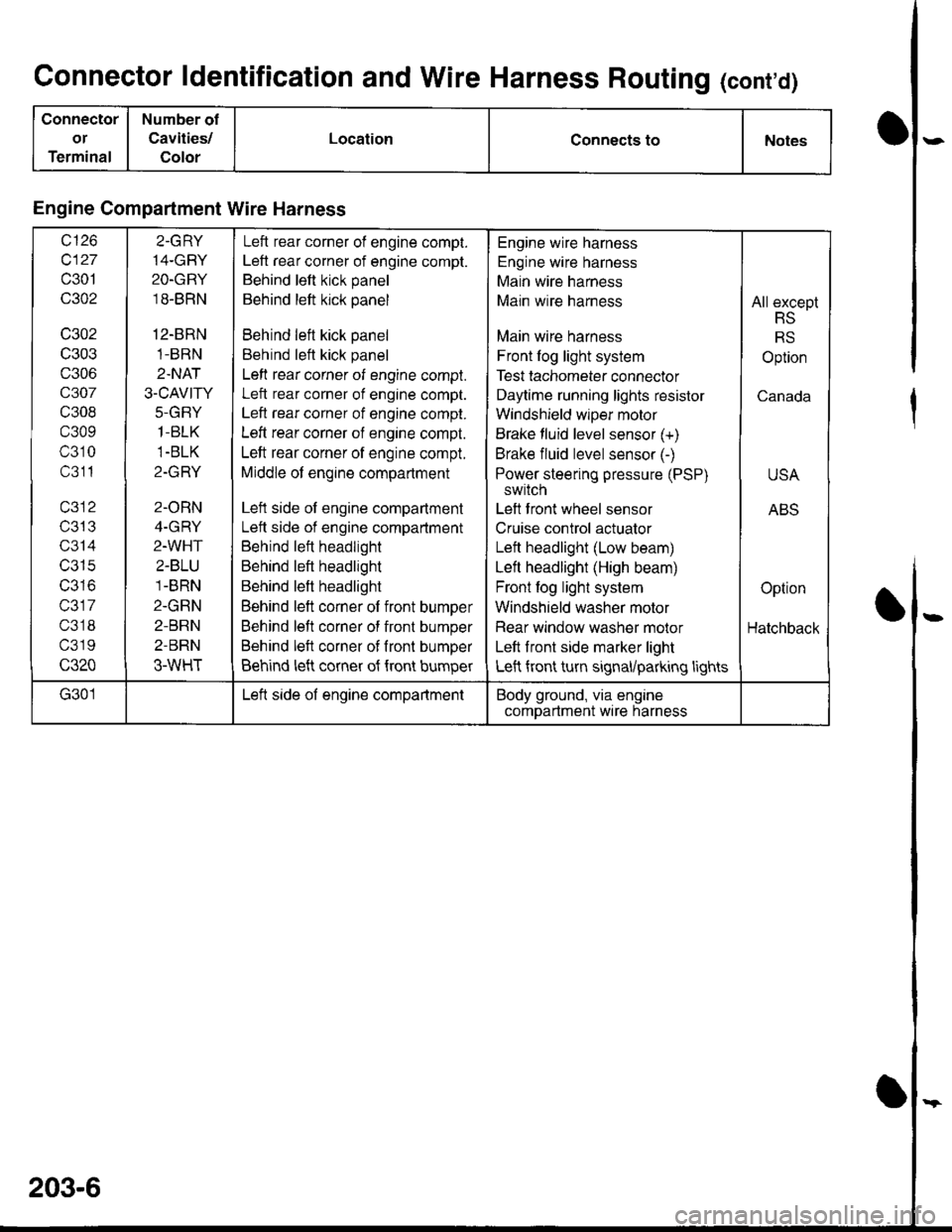
Connector ldentification and Wire Harness Routing (cont'd)
Connector
or
Terminal
Number of
Cavities/
Color
LocationConnects toNotes
Engine Compartment Wire Harness
wt10
c127
c301
c302
c302
c303
c306
c307
c308
c309
c310
c311
T/JIJ
c314
c315
IJJ IO
c317
c318
c319
c320
2.GRY
14-GBY
2O-GRY
18-BRN
12-BRN
1-BRN
2.NAT
3.CAVITY
J-(l|-I Y
1-BLK
1-BLK
Z-IfFI T
2-ORN
4-GRY
2-WHT
2-BLU
1-BRN
2-GRN
2-BRN
2-BRN
3-WHT
Left rear corner of engine compt.
Left rear corner of engine compt.
Behind left kick panel
Behind left kick panel
Behind left kick panel
Behind left kick panel
Left rear corner of engine compt.
Left rear corner of engine compt.
Left rear corner of engine compt.
Left rear corner of engine compt.
Left rear corner of engine compt.
Middle of engine compartment
Left side of engine compartment
Lett side of engine compartment
Behind left headlight
Behind left headlight
Behind left headlight
Behind left corner of front bumper
Behind left corner of front bumper
Behind left corner of fronl bumper
Behind left corner of {ront bumper
Engine wire harness
Engine wire harness
Main wire harness
Main wire harness
Main wire harness
Front log light system
Test tachometer connector
Daytime running lights resistor
Windshield wlper motor
Brake fluid level sensor (+)
Brake fluid level sensor (-)
Power steering pressure (PSP)
switch
Left front wheel sensor
Cruise control actuator
Left headlight (Low beam)
Left headlight (High beam)
Front fog light system
Windshield washer motor
Rear window washer molor
Left front side marker light
Left front turn signal/parking lights
All except
RS
RS
Option
Canada
USA
ABS
Option
Hatchback
G301Left side of engine compartmentBody ground, via engine
comDartment wire harness
203-6
Page 1604 of 1681
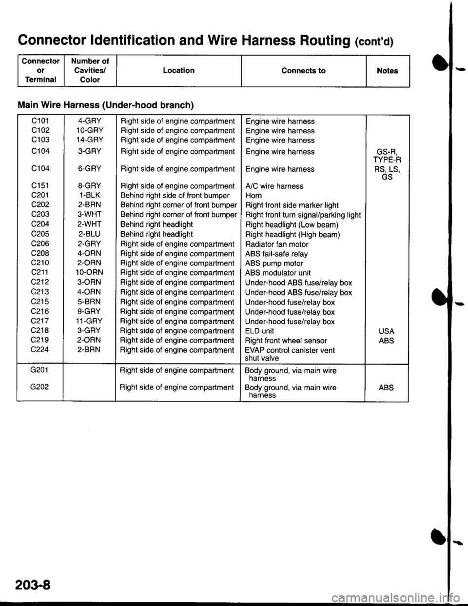
Connector ldentification and Wire Harness Routing (conrd)
Connector
ot
Terminal
Number of
Cavities,/
Color
LocationConnects toNotes
Main Wire Harness (Under-hood branch)
c101
c102
cl03
c104
c104
c151
c201
c202
c203
c204
c205
c206
c208
c210
c211
c212
c213
c215
wz to
c217
c218
c219
4-GBY
1O.GRY
14.GRY
3-GRY
6-GRY
8.GRY
1-BLK
2-BRN
3.WHT
2-WHT
2-BLU
2-GRY
4-ORN
2-ORN
10-oRN
3-ORN
4-ORN
5.BRN
9.GRY
11-GBY
3-GBY
2-ORN
2-BRN
Right side of engine compadment
Right side of engine compartment
Right side of engine compartment
Right side of engine compartment
Right side of engine compartment
Right side of engine compartment
Behind right side of front bumper
Behind right corner of front bumper
Behind right corner of front bumper
Behind right headlight
Behind right headlight
Right side of engine compartment
Righl side of engine compartment
Right side of engine compartment
Bight side of engine compartment
Right side of engine compartment
Right side of engine compartment
Right side of engine compartment
Right side of engine companment
Right side of engine compartment
Right side of engine compartment
Right side of engine compartment
Right side of engine compartment
Engine wire harness
Engine wire harness
Engine wire harness
Engine wire harness
Engine wire harness
A,/C wire harness
Horn
Right f ront side marker light
Right front turn signal/parking light
Right headlight (Low beam)
Right headlight (High beam)
Radiator fan motor
ABS faiFsafe relay
ABS pump molor
ABS modulator unit
Under-hood ABS fuse/relay box
Under-hood ABS tusehelay box
Under-hood fuse/relay box
Under-hood fuse/relay box
Under-hood fuse/relay box
ELU UNII
Right front wheel sensor
EVAP control canister vent
shut valve
GS.R,
TYPE-R
RS, LS,
GS
USA
ABS
Right side of engine compartment
Right side of engine compartment
Body ground, via main wire
harness
Body ground, via main wireharnessABS
2()3€