turn signal HONDA INTEGRA 1998 4.G Owner's Manual
[x] Cancel search | Manufacturer: HONDA, Model Year: 1998, Model line: INTEGRA, Model: HONDA INTEGRA 1998 4.GPages: 1681, PDF Size: 54.22 MB
Page 465 of 1681
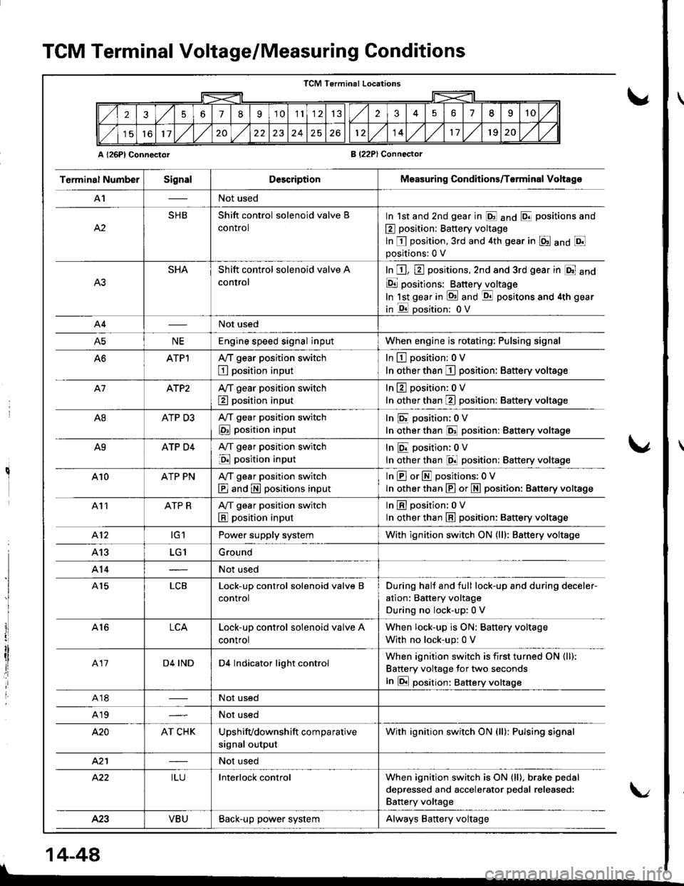
TCM Terminal Voltage/Measuring Conditions
A l26Pl ConnectorB (22PlConnector
TCM Terminal Locations
256789'1011132351II10
11,/l/2024261214,/l/1120,/1,/
T6rminal NumberSignalDescriptionMeasuring Conditions/T€rminal Voltag€
A'INot used
A2
SHBShift control solenoid valve B
control
In 1st and 2nd gear in E anO E positions and
E position: Battery voltage
ln E position,3rd and 4th gear in E anO Epositions:0 V
SHAShift control solenoid valve A
control
In E, E positions,2nd and 3rd gear in E and
E positions: Batteryjloltage
In lst gear in !d and -qtl positons and 4th gear
in E oosition: 0V
A4Not used
A5NEEngine speed signal inputWhen engine is rotating: Pulsing signal
ATPlA,/T gear position switch
E position input
In L!-l position: 0 V
In other than I position: Battery voltage
A7ATP2Ay'T gear position switch
E position input
In 13 position:0 V
In other than E position: Battery voltage
A8ATP D3A,/T gear position switch
E position input
In E position:0V
In other than @ position: Battery voltage
A9ATP D4A,/T gear position switch
E position input
InEposition;0V
In other than El position: Battery voltage
410ATP PNA,/T gear position switch
E and E positions input
InEorEpositions:OV
In other than E or N position: Battery vottage
411ATP RA/T gear position switch
E position input
lnEposition: oV
ln other than E position: 8attery voltage
412tGlPower supply systemWith ignition switch ON (lll: Battery voltage
413LG1Ground
A14Not used
A15LCBLock-up control solenoid valve B
control
During hall and full lock-up and during deceler-
ation: Battery voltage
During no lock-up:0 V
A16LCALock-up control solenoid valve A
control
When lock-up is ON; Battery voltage
With no lock-up: 0 V
417D4 INDD4 Indicator light controlWhen ignition switch is first turned ON (ll):
Battery voltage for two seconds
In E position: Battery voltsge
A18Not used
A19Not used
420AT CHKUpshifvdownshift comparative
signal output
With ignition switch ON (ll): Pulsing signal
421Not used
422ILUInterlock controlWhen ignition switch is ON (ll), brake pedal
deoressed and accelerator oedal released:
Battery voltage
423VBUBack-up power systemAlways Battery voltage
I
lI
I
14-44
\/
Page 472 of 1681
u.drrf,,
J
J
J
14-55
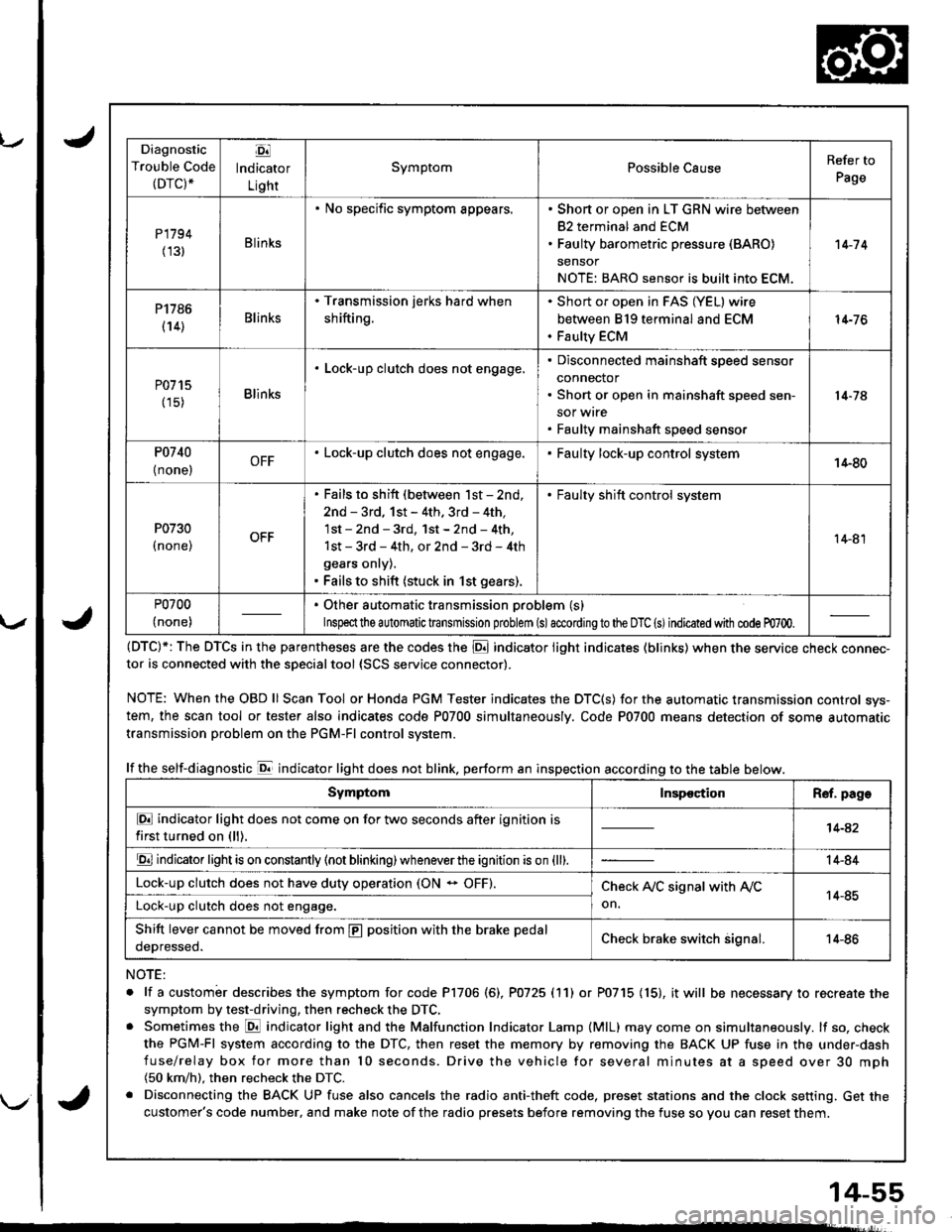
Diagnostic
Trouble Code(DTC).
Ej
lndicator
Light
SymptomPossible CauseRefer to
Page
P1794
(131Blinks
. No specific symptom appears.. Short or open in LT GRN wire between
82 terminal and ECM. Faulty barometric pressure (BARO)
sensor
NOTE: BARO sensor is built into ECM.
't 4-7 4
P1786
(14)Blinks
. Transmission jerks hard when
shifting.
Short or open in FAS (YEL) wire
between 819 terminal and ECM
Faulty ECM
14-76
P0715
(15)Blinks
. Lock-up clutch does not engage,Disconnected mainshaft speed sensor
connector
Short or open in mainshaft speed sen-
sor wrre
Faulty mainshaft speed senso.
14-74
P0740
{ none,OFF. Lock-up clutch does not engage.Faulty lock-up control system14-80
P0730
I none,
. Fails to shift (between lst - 2nd,
2nd - 3rd, 1st - 4th. 3rd - 4th,
1st - 2nd - 3rd, 1st - 2nd - 4th,
1st - 3rd - 4th, or 2nd - 3rd - 4th
gears onry).. Fails to shift (stuck in 1st gears).
. Faulty shift control system
14-81
P0700
(none)
. Other automatic transmission problem (s)
Inspeclthe a utomatic transmission problem (s)accordingto the DTC (s)indicated with code m700.
(DTC)*: The DTCS in the parentheses are the codes the E indicator light indicates (blinks) when the service cnecK connec-tor is connected with the sDecialtool {SCS service connector).
NOTE: WhentheOBDll Scan Tool orHonda PGM Tester indicates the DTC(S) for the automatic transmission control sys-
tem, the scan tool or tester also indicates code P0700 simultaneously. Code P0700 means detection of some automatic
transmission problem on the PGM-Fl control system.
lf the self-diagnostic E indicator light does not blink. perform an inspection according to the table below.
NOTE:
. lf a custombr describes the symptom for code P1706 (6), P0725 (11) or P0715 (15), it will be necessary to recreate the
symptom by test-driving, then recheck the DTC,. Sometimes the E indicator light and the Malfunction Indicator Lamp (MlL) may come on simultaneously. lf so, check
the PGM-Fl system according to the DTC, then reset the memory by removing the BACK UP fuse in the under-dash
fuse/relay box for more than l0 seconds. Drive the vehicle for several minutes at a speed over 30 mph(50 km/h). then recheck the DTC.
. Disconnecting the BACK UP fuse also cancels the radio anti-theft code, preset stations and the clock setting. Get the
customer's code number, and make note of the radio presets before removing the fuse so you can reset them.
SymptomInspectionR€f. page
E indicator light does not come on for two seconds after ignition is
first turned on (ll).14-42
E indicator light is on constantly (not blinking) wheneverthe ignition is on {ll).14-84
Lock-up clutch does not have duty operation (ON - OFF).Check A,/C signal with Ay'C
on.14-85Lock-up clutch does not engage.
Shift lever cannot be moved from E position with the brake pedal
oeDresseo.Check brake switch signal.14-86
Page 493 of 1681
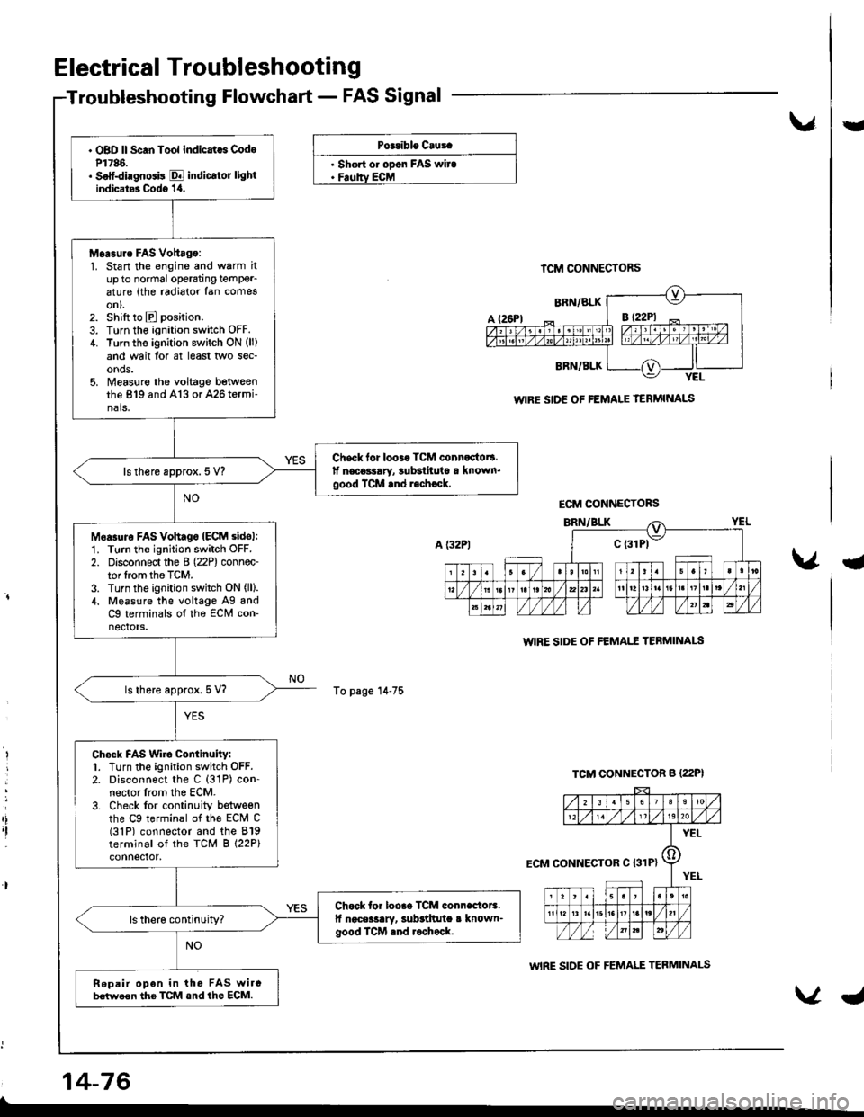
. OBD ll Scan Tool indicatcs CodeP1786.. Soff-diagnGis E indicrtor lightindicat6 Codo '1,0.
M6a3ure FAS Vottago:1. Start the engine and warm itup to normal operatang temPer_6ture (the radiator fan comeson).2. shift to E position.
3. Turn the ignition switch OFF.4. Turn the ignition switch ON (ll)
and wait lor at least two sec-onds.5. Measlre the voltage betweenthe 819 and A13 or A26 termi-nals.
Chsck for loo3r TCM connactot!.lf necoslary, lubsihuto a known.good TCM rnd r.chrck,ls there approx. 5 V?
M6asuro FAs vohagoIECM sidol:1. Turn the ignition switch OFF.
2. Disconnect the B (22P) connec-tor lrom the TCM.3. Turn the ignition switch ON (ll).
4. Measure the voltage Ag andC9 terminals of tho ECM con-nectors.
ls there approx. 5 V?
Chock for loore TCM connectoE.lf noceilary, subrtitula a known-good ICM rnd rcchock.
Repair opon in the FAS wircb€(we€n the TCM snd ths ECM.
Electrical Troubleshooting
Troubleshooting Flowchart - FAS Signal
vU
PG.iblo Cru!.
. Short o. opon FAS wira. Feoltv ECM
To page 14-75
TCM CONNECTORS
WIRE SIDE OF FEMALE TERMINALS
WIRE SIDE OF FEMAI.T TEBMINAI-S
WIRE SIDE OF FEMALE TERMINALS
a
,i,I
Chock FAS Wiro Continuity:1. Turn the ignition switch OFF.2. Disconnect the C (31P) con-nector lrom the ECM.3. Check lor continuity betweenthe C9 terminal of the ECM C(31P) connector and the 819terminal of the TCM B (22P)
14-76
ECM CONNECTORS
ECM CONNECTOR C I31P}
Page 503 of 1681
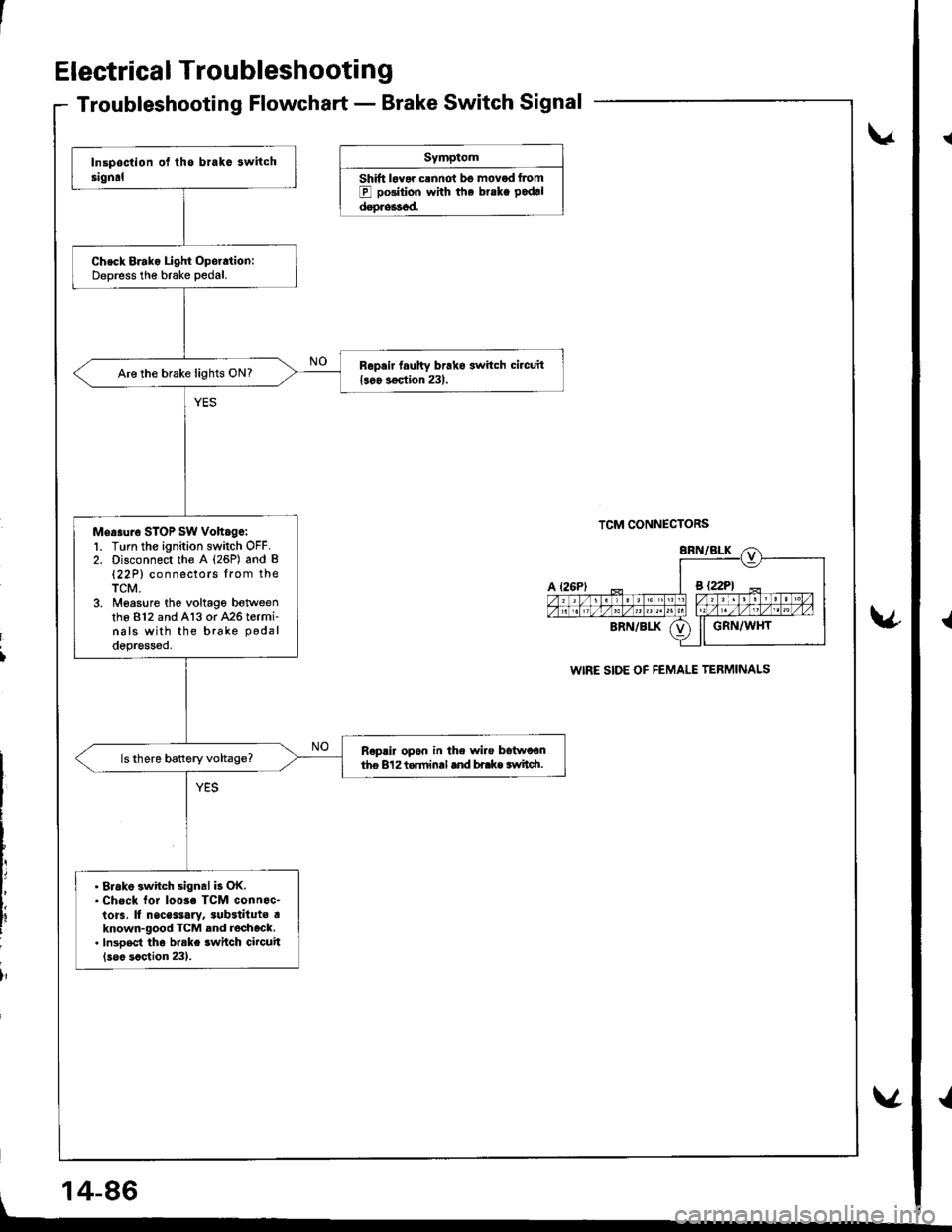
Electrica I Troubleshooti n g
Troubleshooting Flowchart - Brake Switch Signal
Symptom
Shift lovar clnnot bo moved Itom
E pGition with the brske pod.l
dsoressod.
v
TCM CONNECTORS
WIRE SIDE OF FEMALE TERMINALS
v
i
lr
Check Brako Light Oporation:Deoress the brake Dedal.
Repair taulty brako switch circuit{soo 3€qtion 231.Are the brake lights ON?
Mea.ur6 STOP sw voh.ge:1. Turn the ignition switch OFF.2. Disconnect the A (26P) and B(22P) connectors lrom theTCM.3. Moasure the voltage botweenthe 812 and A13 or 426 termi-nals with the brake podal
depressed.
R€plir opon in the wire Itstwoonth€ 8'l2 torminal and bi.ke svtidt.
. 8rak6 switch signal b OK.. check lor loose TcM connoc-to]s, lf nsce$ary, sub3tituts aknown-good TcM and rochock.. lnsooct tho brake swilch circuit(soo scction 231.
, 14-86
v
{
{
Page 677 of 1681
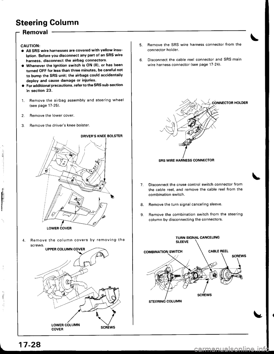
Steering Golumn
Removal
I
a All SRS wire harnesses are covered with yellow insu-
lation. Before vou disconnect any pan of an SRS wire
harness, disconnect the airbag Gonnectors.
a Whenever the ignition switch is ON (lll, or has been
turned OFF for less than three minutes, be carelul not
to bump the SRS unit; the airbags could accidentally
deploy and cause damage or iniuries.
a For additional precautions, lelel to the SRS sub-section
in section 23.
1. Remove the airbag assembly and steering wheel
(see page 17-25).
2. Remove the lower cover.
3. Remove the driver's knee bolster,
Remove the column covers by removing the
screws.
'//
,,1G
LOWER COVER
17 -28
1.
9.
Remove the SRS wire harness connector from the
connector holder.
Disconnect the cable reel connector and SRS main
wire harness connector (see page 17-24).
CONNECTOR HOI-DER
SRS WIRE HARNESS CONNECTOR
Disconnect the cruse control switch connector from
the cable reel, and remove the cable reel trom the
combination switch.
Remove the turn signal canceling sleeve.
Remove the combination switch from the steering
column by disconnecting the connectors.
Page 682 of 1681
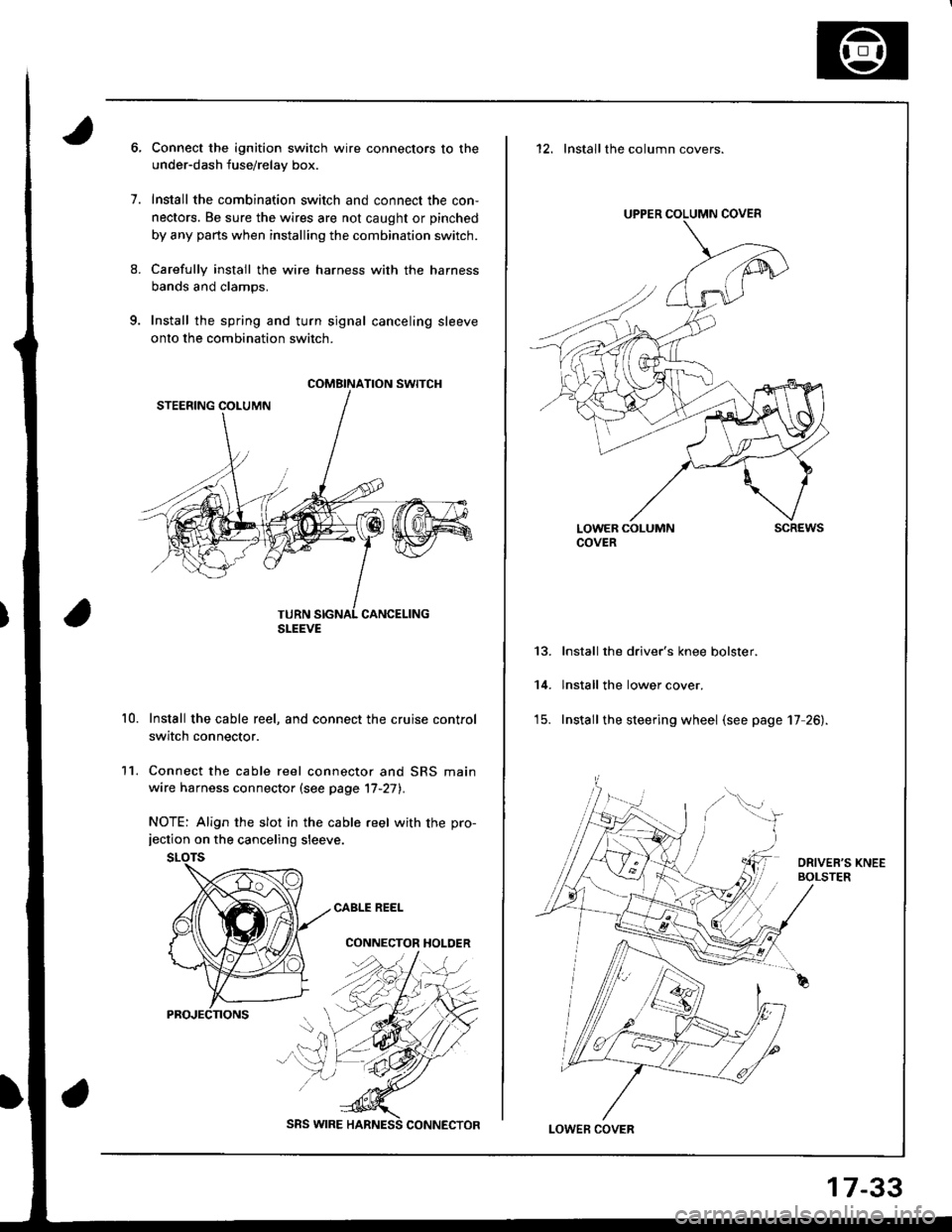
9.
1.
8.
11.
10.
Connect the ignition switch wire connectors to the
under-dash fuse/relay box.
Install the combination switch and connect the con,
nectors. Be sure the wires are not caught or pinched
by any parts when installing the combination switch.
Carefully install the wire harness with the harness
bands and clamps.
Install the spring and turn signal canceling sleeve
onto the combination switch.
Install the cable reel, and connect the cruise control
switch connector.
Connect the cable reel connector and SRS main
wire harness connector (see page '17-27).
NOTE: Align the slot in the cable reel with the pro-jection on the canceling sleeve.
CABLE REEL
CONNECTOR HOLDER
COMBINATION SWITCH
SLEEVE
SRS WIRE
17-33
12. Installthe column covers.
UPPER COLUMN COVER
LOWER COLUMNCOVERscREws
13.
14.
Install the driver's knee bolster.
lnstall the lower cover.
Install the steering wheel (see page 17 26).
LOWEF COVER
Page 779 of 1681
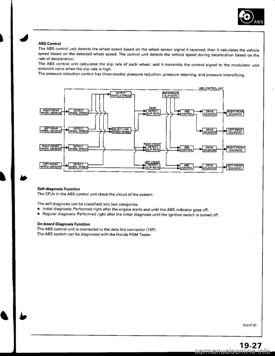
IABS Control
The ABS control unit detects the wheel speed based on the wheel sensor signal it received, then it calculates the vehiclespeed based on the detected wheel speed. The control unit detects the vehicle speed during deceleration based on therate of deceleration.
The ABS control unit calculates the slip rate of each wheel, and it transmits the control signal to the modulator unitsolenoid valve when the slip rate is high.
The pressure reduction control has three-modes: pressure reduction, pressure retaining, and pressure intensifying.
Self-diagnosis Function
The CPUS in the ABS control unit check the circuit of the system.
The self-diagnosis can be classifield into two categories.. Initial diagnosis: Performed right after the engine starts and until the ABS indicator gose off.. Regular diagnosis: Performed right after the initial diagnosis until the ignition switch isturnedoff.
On-board Diagnosis Function
The ABS control unit is connected to the data link connector fi6p).The ABS system can be diagnosed with the Honda PGM Tester.
(cont'd)
19-27
Page 784 of 1681
![HONDA INTEGRA 1998 4.G Owners Manual ABS Gontrol Unit Terminal Arrangement
ABS CONTROL UN]T 22P CONNECTOR
Wire side oI female t6rminals
Terminal
numbel
Wire
Golor
Terminsl sign
{Terminal
namet
Description
Measurgmgnt
TerminalConditions
{ HONDA INTEGRA 1998 4.G Owners Manual ABS Gontrol Unit Terminal Arrangement
ABS CONTROL UN]T 22P CONNECTOR
Wire side oI female t6rminals
Terminal
numbel
Wire
Golor
Terminsl sign
{Terminal
namet
Description
Measurgmgnt
TerminalConditions
{](/img/13/6069/w960_6069-783.png)
ABS Gontrol Unit Terminal Arrangement
ABS CONTROL UN]T 22P CONNECTOR
Wire side oI female t6rminals
Terminal
numbel
Wire
Golor
Terminsl sign
{Terminal
namet
Description
Measurgmgnt
TerminalConditions
{lgnition swhch ON {ll}}Voltage
1BLK/WHTGND3(Ground 3)
Ground1.GNDBelow 0.3 V
4GRN/REDPARK
{Parking)
Detects parking brake
switch signal4-GNDParking
brake
PulledBelow 0.3 V
Battery voltage
LT GRN/
BLK
FLW (-)
{FronLleft
wheel negative)
Detects left-front wheel
sensor srgnal
0.053 V or
above
0sci\oscope:
0.15 Vp-p or
above
7GBN/ORN
FLW (+)
(Front-left
wheel positive)- | Turn wheel at
E
1 turntsecona
l'GRN
FRW (-)
(Front-right
wheel negative)
Detects right-f ront wheel
sensor slgnal
8-9
1 FR\N (+)
I \GRN/BLK (Front-right
I I wheelpositiveStops0.25 - 1.15 V
10GRN/WHTSTOPDetects brake switch signal1O.GNDBrake pedalDepressedBaftery voltage
ReleasedBelow 0.3 V
11BLK/TELtG2
(lgnition 2)
Power source for activating
the system11-GNDlgnition
switch
oN {I)Battery voltage
Start (lll)Below 0.3 V
19-32
Page 785 of 1681
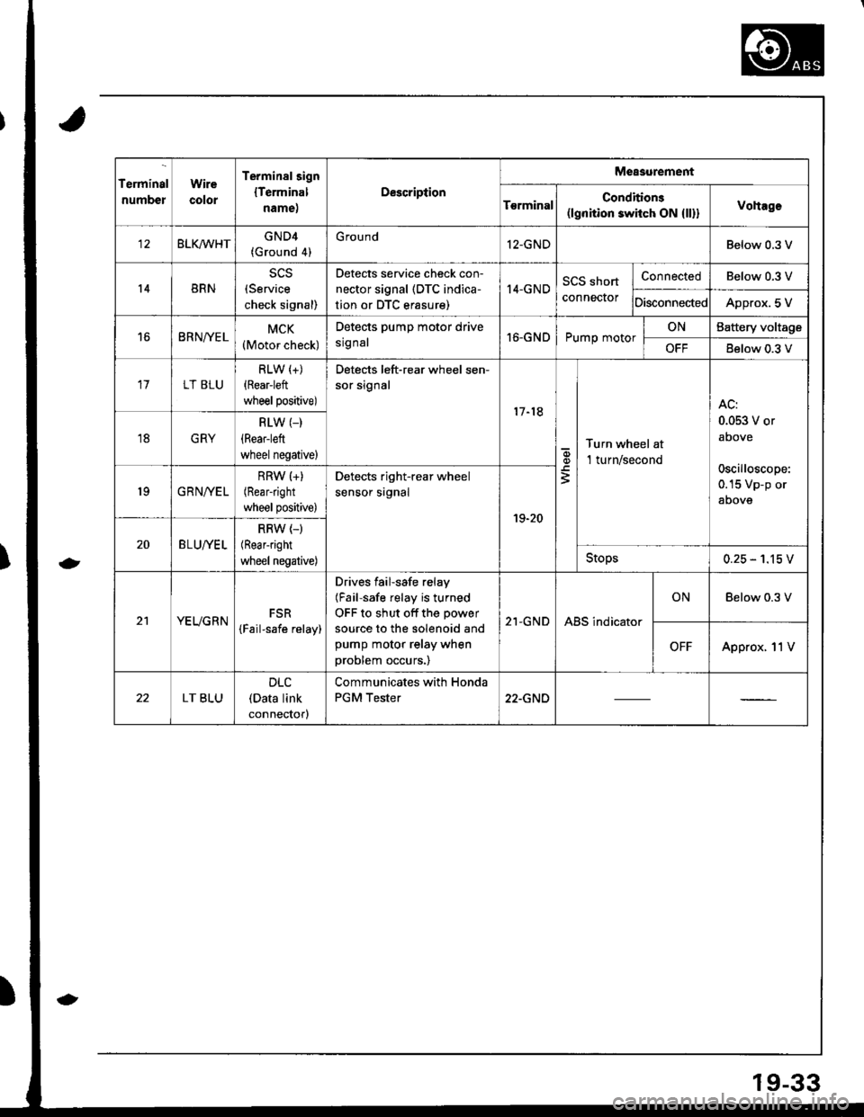
Terminal
numbel
Wire
color
Terminalsign
lTerminal
name,
Description
Measurement
T€rminalConditions(lgnition switch ON {ll}}Vohage
BLKMHTGND4(Ground 4)
G round12-GNDBelow 0.3 V
14BRN(Service
check signal)
Detects service check con-
nector signal (DTC indica-
tion or DTC erasure)
I4-GNDSCS short
connector
ConnectedBelow 0.3 V
DisconnectedApprox. 5 V
16BRNfYELMCK(Motor check)
Detects pump motor drive
srg nal16-GNDPump motorONBattery voltage
OFFBelow 0.3 V
17LT BLU
RLW (+)
{Rear-left
wheel positive)
Detects left-rear wheel sen-
sor signal
17-18
q,
3
Turn wheel at
l turn/second
AC:
0.053 V or
above
oscilloscope:
0.15 Vp-p or
aoove
18GRY
RLW (_)
(Rear-left
wheel negative)
19GRNIVEL
RRW (+)
(Rearright
wheel positive)
Detects right-rear wheel
sensor srgnal
19-20
20BLU//EL
RRW (-)
(Rear-right
wheel negative)Stops0.25 - 1.15 V
21YEUGRNFSR
{Fail-safe relay)
Drives failsafe relay
(Fail-safe relay is turned
OFF to shut off the power
source to the solenoid and
pump motor relay when
problem occurs.)
21-GNDABS indicator
ONBelow 0.3 V
OFFApprox. 11V
LT BLU
DLC(Data link
connectorl
Communicates with Honda
PGM Tester22-GND
19-33
Page 787 of 1681
Troubleshooting Precautions
ABS lndicator
1. lf the system is OK. the ABS indicator goes off two seconds after turning the ignition switch ON (ll) without starting
the engine, and then comes on again and goes off after two seconds. This occurs because the ABS control unit is
turned on bv the lG2 oower source.
2. The ABS indicator comes on when the ABS control unit detects a problem in the system. However, even though the
system is operating properly, the ABS indicator will come on under the following conditions.. Onlv drive wheels rotate
. One drive wheel is stuck
. Vehicle spin
. ABS continues to operate for a long time
. Signal disturbance
To determine the actual cause of problem. question the customer about the problem, taking these conditions into
consideration.
3. When a problem is detected and the ABS indicator comes on, there are cases when the indicator stays on until the
ignition switch is turned OFF, and cases when the indicator goes off automatically when the system returns to nor-
mal. For DTCS 61 and 62, the indicator goes off automatically when the system returns normal. For all other codes.
the indicator stays on until the ignition switch is turned OFF.
4. For DTCS 12, 14, 16, '18, 2'1,22, 23, 24,51,52 and 53, the indicator goes off when the vehicle is driven again and the
system is OK after the ignition switch is turned from OFF to ON (ll). However, if the DTC is erased, the CPU is reset
and the indicator goes off right after the engine is started if the system is OK.
Diagnostic Trouble Code (DTC)
1. lf the CPU cannot be actlvated and the indicator comes on, the DTC is not memorized.
2. The memory can hold any number of DTCS. However, when the same DTC is detected more than once, the later one
is written over the old one. Therefore, when the same problem is detected repeatedly, it is memorized as one DTC.
3. The DTCs are indicated in the order of ascending number, not in the order they occur.
4, The DTCS are memorized in the EEPROM (non-volatile memory). Therefore, the memorized DTCS cannot be canceled
by disconnecting the battery. Perform the specified procedures to erase the DTCS,
S6lt-dirgnosis
1. Self-diagnosis can be classifield into two categories.
. Initial diagnosis: Performed right afterthe enginestansand untiltheABS indicator goes off.. Regular diagnosis: Performed rightafterthe initial diagnosis untilthe ignition switch isturned OFF.
2. When a problem is detected by self-diagnosis, the system
. Turns the fail-safe relay OFF
. Turns the solenoid valve OFF
. Turns the oumo motor OFF
. Turns the ABS indicator ON