turn signal HONDA INTEGRA 1998 4.G Repair Manual
[x] Cancel search | Manufacturer: HONDA, Model Year: 1998, Model line: INTEGRA, Model: HONDA INTEGRA 1998 4.GPages: 1681, PDF Size: 54.22 MB
Page 1343 of 1681
)
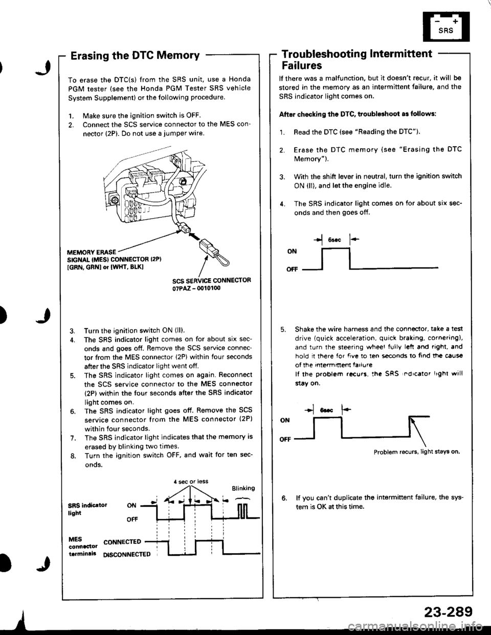
Erasing the DTC Memory
To erase the DTC(S) from the SRS unit, use a Honda
PGM tester (see the Honda PGM Tester SRS vehicle
System Supplement) or the following procedure.
1. Make sure the ignition switch is OFF.
2. Connect the SCS service connector to the MES con-
nector (2P). Do not use a jumper wlre.
MEMORY EMSESIGNAL {MESI CONNESTOR I2P)
[GRN, GBNI or IWHT, BLKI
Turn the ignition switch ON (ll).
The SBS indicator light comes on for about six sec-
onds and goes off. Remove the SCS service connec-
tor from the MES connector (2P) within four seconds
after the SRS indicator light went off.
The SRS indicator light comes on again. Reconnect
the scs service connector to the MES connector
(2P) within the four seconds after the SRS indicator
light comes on.
The SRS indicator light goes off. Remove the SCS
service connector from the MES connector (2P)
within four seconds.
The SRS indicator light indicates that the memory is
erased by blinking two times.
Turn the ignition switch OFF. and wait for ten sec-
onos.
Troubleshootin g Intermittent
Failures
lf the.e was a malfunction, but it doesn't recur, it will be
stored in the memory as an intermittent failure, and the
SRS indicator light comes on,
Atter chocking ths DTC, troubleshoot as follows:
1. Read the DTC (see "Reading the DTC").
2. Erase the DTC memory (see "Erasing the DTC
Memory").
3. With the shift l€ver in neutral, turn the ignition switch
ON (ll), and let the engine idle.
4. The SRS indicator light comes on for about six sec-
onds and then goes off.
I o"* 1--
ONllI
Shake the wire harness and the connector, take a test
drive (quick acceleration, quick braking, cornering),
and turn the steering wheel fully left and righi, and
hold I there for fve to ten s€conds lo 6nd tt|e caus€
of the intermnem farlure
It lhe problem .!curs, lha SRS nd'calor r'ghl will
$aY on.
,l soc or less
Problem recurs, Iight stays on
lf vou can't duplicate the intermittent failure, the sys-
tem is OK at this time.SRS indic.lollight
MESconnaclottarrninlll
CONNECTED
DISCONNECTED
23-289
Page 1383 of 1681
).1
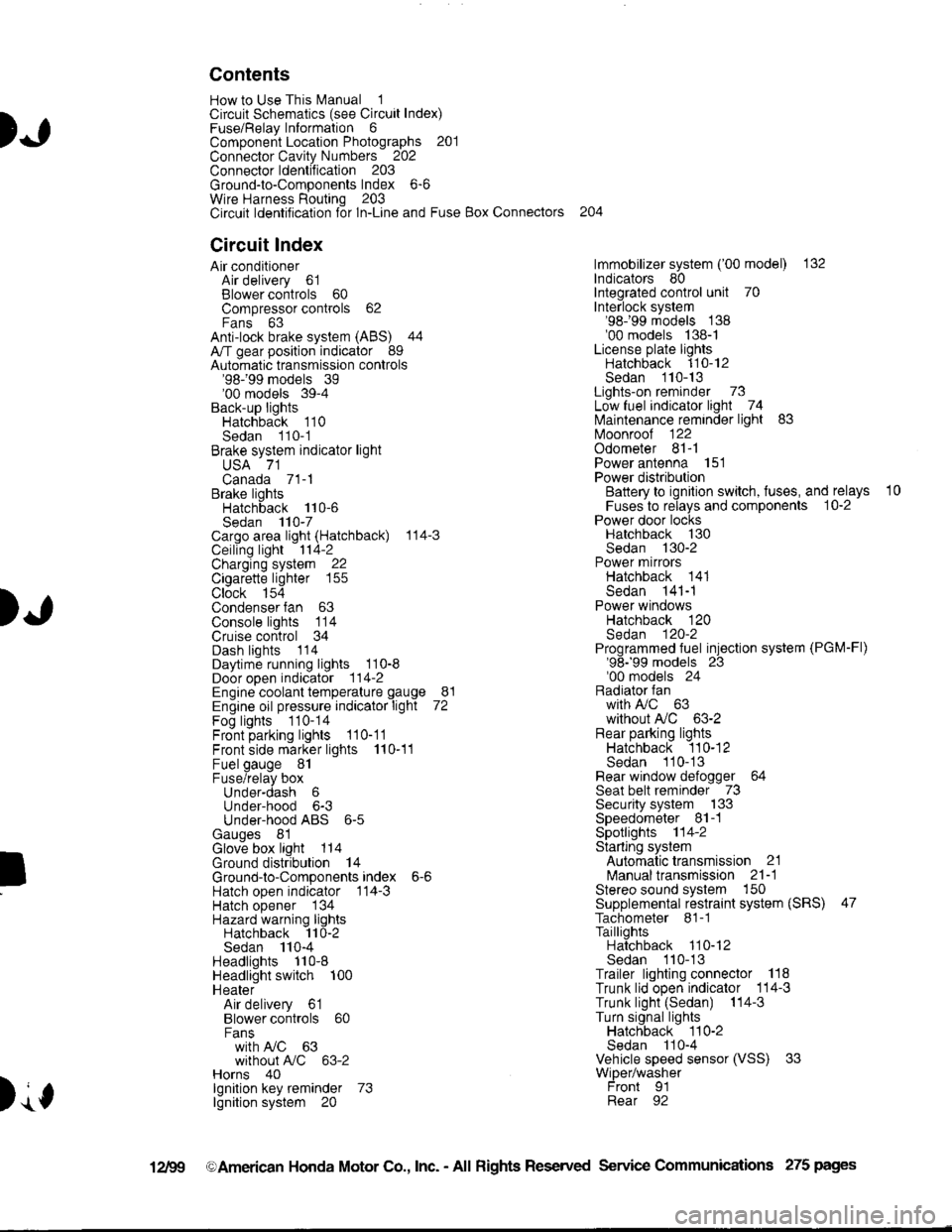
Contents
How to Use This l\.4anual 1Circuit Schematics (see Circuit Index)Fuse/Relaylnformation 6ComponentLocation Photographs 201
Connector Cavity Numbers 202Connectorldentification 203
Ground-to-Components Index 6-6Wire Harness Routing 203Circuit ldentification lor ln-Line and Fuse Box Connectors
Circuit Index
Air conditionerAir delivery 61Blower controls 60Compressor controls 62Fans 63Anti-lock brake system (ABS) 44A/T gear position indicator 89Automatic transmission controls'98199 models 39'00 models 39-4Back-up lightsHatchback 110Sedan 110- 1Brake system indicator light
USA 71Canada 71-1Brake lightsHatchback 110-6Sedan 110-7Cargo area light (Hatchback) 114-3Ceiling light 114-2Charging system 22Cigarette lighter 155
Clock 154Condenser fan 63Console lights 114Cruise control 34Dash lights 1 14Daytime running lights 110-8Door open indicator 114-2Engine coolant temperature gauge 81Engine oil pressure indicator light 72Fog lights 110-14Front parking lights 110-11Front side marker lights 110-11Fuel gauge 81Fuse/relay boxUnder-dash 6Under-hood 6-3Under-hood ABS 6-5Gauges 81Glove box light 114Ground distribution 14Ground-to-Componentsindex 6-6Hatch open indicator '114-3
Hatch opener '134
Hazard warning lightsHatchback 'l l0-2Sedan 110-4Headlights 1'10-8Headlight switch 100HeaterAir delivery 61Blower controls 60Fanswith A,/C 63without A,/C 63-2Horns 40lgnilion key reminder 73lgnition system 20
204
lmmobilizer system ('00 model) 132lndicators 80Integrated control unit 70Interlock system'98199 models 138'00 models 138-1License plate lightsHatchback 110-12Sedan 110-13Lights-on reminder 73Low fuel indicator light 74l\,4aintenance reminder light 83l\iloonroof 122Odometer 81-1Power antenna 151Power distributionBattery to ignilion switch, fuses, and relays
Fuses to relays and components 10-2Power door locksHatchback '130
Sedan 130-2Power mirrorsHatchback 141Sedan 141-1Power windowsHatchback 120Sedan 120-2Programmed fuel injection system (PGM-Fl)'98199 models 23'00 models 24Radiator fanwith tuC 63without A,/C 63-2Rear parking lightsHatchback 110-12Sedan 110- 13Rear window defogger 64Seat belt reminder 73Security system 133Speedometer Il-1Spotlights 114-2Starting syslemAutomalictransmission 21l\.4anualtransmission 21-1Stereo sound system 150Supplemental restraint system (SRS) 47Tachometer 81- 1TaillightsHatchback 110-12Sedan 110-13Trailer lighting conneclor 118Trunk lid open indicator 114-3Trunk light (Sedan) 114-3Turn signal lightsHatchback 110-2Sedan 110-4Vehicle speed sensor (VSS) 33Wiper/washerFront 91Rear 92
10
).1
I
Xr
12Fg oAmerican Honda Motor Co., Inc. - All Rights Reserved Service Communications 275 pages
Page 1388 of 1681
)a
)a
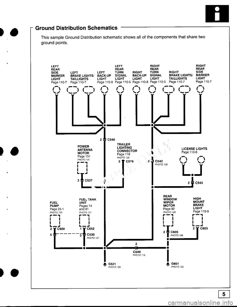
'ouno ulslnoulron Scnemarlcs -
This samDle Ground Distribution schematic shows all of the components thal share two
ground points.
LEFT RIGHT RIGHTREAR REAR REARLEFT LEFT TURN RTGHT TURN RIGHT SIDEBRAKE LIGHTS/ BACK-UP SIGNAL BACK-UP SIGNAL BRAKE LIGHTS/ MARKER
TAILLTGHTS LIGHT LIGHT LIGHT LIGHT TAILLIGHTS LIGHT
Page110-7 Page110-8 Page110-5 Page110-8 Page110'5 Page110-7 Page110-7
r--r r--t t- t-l t-t ,-t r--r r--t r-\t*-r r--r \./ \/ \./ \/ \/
I LICENSE LIGHTS
I Page 110'6
l"uo, O O
l*"''* L.J
!-.1**
FUELPUMPPage 23-1
lltl
LEFTREARstoEMARKERLIGHTPage 110-7
POWERANTENNAMOTORPage 151
tlll
:E_,
a-al
JL
c549
t\
HIGHMOUNTBRAKELIGHTPage 110-9
ttll
REARwtNDowWIPERMOTORPage 92
tlll
iIn*
a-
Ira
T!. G601
FUEL TANKUNITPages 74and 81
tltl
1 Y C652
irg c530- | puoro tzt
I
106
T+ Gs21
c603
Ground DistributiSchematics
E
)o
Page 1406 of 1681
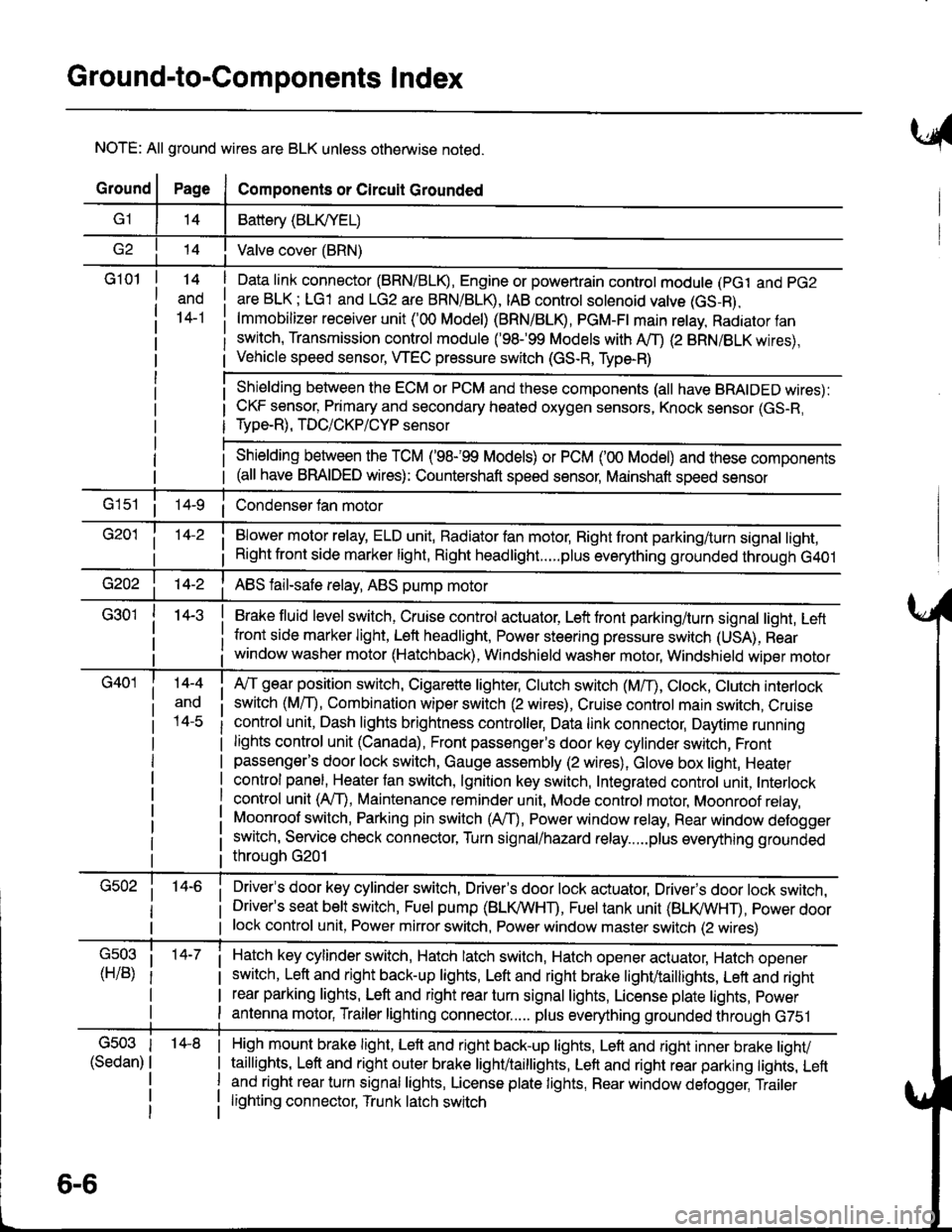
Ground-to-Components I ndex
NOTE: All ground wires are BLK unless otherwise noted.
GroundPageComponents or Circuit Grounded
Battery (BLIVYEL)
--t'I Valve cover (BRN)
G101t.+
and
14-1
Daia link connector (BRN/BLK), Engine or powertrain controt module (pct and pG2
are BLK; LG1 and LG2 are BRN/BLR, IAB controt solenoid valve (GS-B),
lmmobilizer receiver unit ('00 Model) (BRN/BLR, PGM-Ft main retay, Radiator fan
switch, Transmission control module ('98.�99 Models with MD (2 BRN/BLK wires),
Vehicle speed sensor, WEC pressure switch (GS-R, Type-R)
Shielding between the ECM or PCM and these components (all have BRAIDED wires):
CKF sensor, Primary and secondary heated oxygen sensors, Knock sensor (GS-R,
Type-R), TDC/CKP/CYP sensor
Shielding between the TCM ('98-'99 Models) or PCM ('00 Model) and these components(all have BRAIDED wires): Countershaft speed sensor, Mainshaft speed sensor
G1s1 ii Condenser fan motor
Brake fluid level switch, Cruise control actuator, Left front parking/turn signal light, Left
front side marker light, Left headlight, Power steering pressure switch (USA), Rear
window washer motor (Hatchback), Windshield washer motor, Windshield wiper motor
14-3
Blower motor relay, ELD unit, Badiator fan motor, Right front parking/turn signal light,
Right front side marker light, Right headlight.....plus everything grounded through G401
ABS fail-safe relay, ABS pump motor
G40114-4
ano
l4-c
A,/T gear position switch, Cigarette lighter, Clutch switch (M,/T), Ctock, Ctutch interlock
switch (MfD, Combination wiper switch (2 wires), Cruise control main switch, Cruise
control unit, Dash lights brightness controller, Data link connector, Daytime running
lights control unit (Canada), Front passenger's door key cylinder switch, Frontpassenger's door lock switch, Gauge assembly (2 wires), Glove box light, Heater
control panel, Heater tan switch, lgnition key switch, Integrated control unit, Interlock
control unit (AfI), Maintenance reminder unit, Mode control motor, Moonroof relay,
Moonroof switch, Parking pin switch (AfD, Power window relay, Rear window defogger
switch, Service check connector, Turn signal/hazard relay.....plus everything grounded
throuoh G201
Driver's door key cylinder switch, Driver's door lock actuator, Drivels door lock switch,Driver's seat belt switch, Fuel pump (BLI(/WHT), Fuel tank unit (BLI(/WHT), power doorlock control unit, Power mirror switch, Power window master switch (2 wires)
Hatch key cylinder switch, Hatch latch switch, Hatch opener actuator, Hatch ooener
switch, Left and right back-up lights, Left and right brake light/taillights, Lett and right
rear parking lights, Left and right rear turn signal lights, License plate lights, power
antenna motor, Trailer lighting connector..... plus everything grounded through G751
6-6
'14-8G503
(Sedan)
High mount brake light, Left and right back-up lights, Lett and right inner brake tighv
taillights, Left and right outer brake light/taittights, Left and right rear parking tights, Leftand right rear turn signal lights, License plate lights, Rear window detogger, Trailer
lighting connector, Trunk latch switch
Page 1421 of 1681
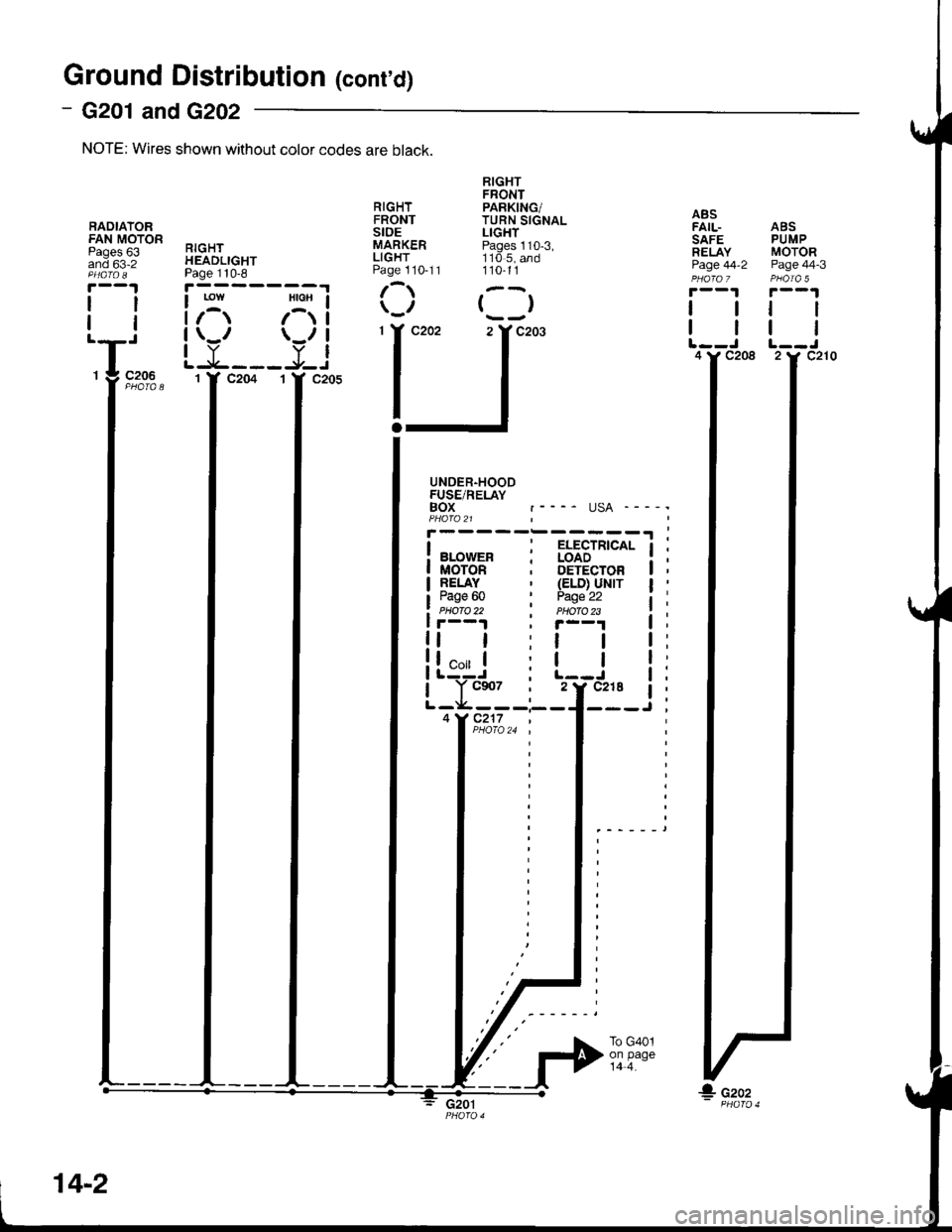
Ground Distribution (conrd)
- G201 and G202
NOTE: Wires shown without color codes are black.
BADIATORFAN MOTORPages 63and 63-2
ll
tl
RIGHTHEADLIGHTPage 110-8
RIGHTFRONTSIDEMARKERLIGHTPage 1 10-1 1
RIGHTFRONTPARKING/TURN SIGNALLIGHTPages 110-3,110 5, and110-11
()
ABSFAIL- ABSSAFE PUMPRELAY MOTORPage 44-2 Page 44-3PHO|A 7 PHOIA 5|.--1r--1
I tt I
I tt I
UNDER-HOODFUSE/RELAYBOX .---- USA ----'PHAfa 21
BLowER : aoAb --'
MOTOR ; DETECTORRELAY ' (ELD) UNITPage 60 ' Peq'e 22PIIOTO 22 . PHOTO2Sr--1.|.--1
| | :t I
[g"ri i l--J
Yc$7 ; 2 t'c218 a
;Y;,;-i---l---J
G201
IA Ai
LY___!jjc2061 Y C204
'l 'J"''L--J L-.J4 I' C208 2Y C210
14-2
Pll;**
Page 1422 of 1681
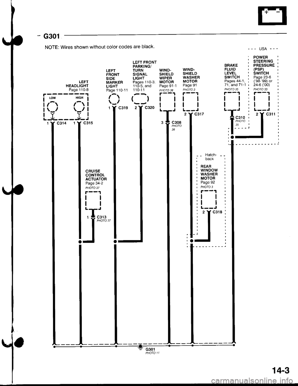
- G301
NOTE: Wires shown without color codes are black.
LEFT FBONTPARKING/LEFT TURN WIND.FRONT SIGNAL SHIELDSIDE LIGHT WIPER
()l
2Y c320 |
--- usA ---
. POWERi sreentlc :BRAKE . PRESSURE ;FLUID ' (PsP)LEVEL ' SWITCHSWITCH : Page 23-6 IPages44-1,, ('98'99) or :71,and71-1 ' 24-6 ('00) ,PHOTO 35 ' PHATA 33r--1 ; r--1
I | :l l;
tt;lt:
WIND-SHIELDWASHERMOTORPage 91
tl
2 Y C317
LEFTHEADLIGHTPage 110-8LIGHTMARKER Pages 110-3, MOTORLIGHT 110-5. and Paqe 91Page 110 11 110-11110 5,Page 91'1
I
I
I
I
CRUISECONTROLACTUATORPage 34'2
ll
-- Hatch' - -' back
I nean :, wtNoow ;, WASHEB. MOTOR
: Page 92 I
:lt:
:t I i
ly
I 2Ycai8:
a
c308
3A
G301
14-3
Page 1426 of 1681
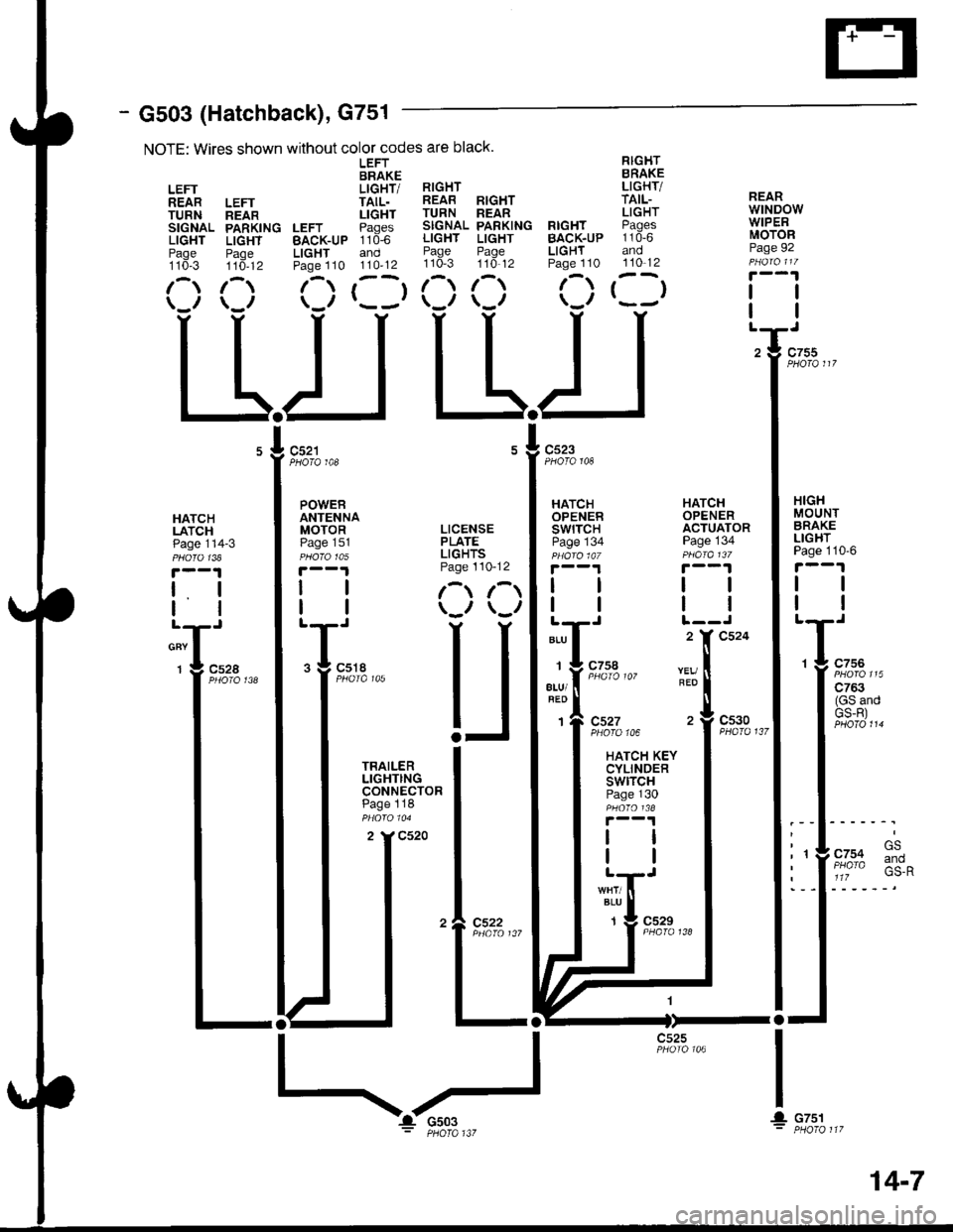
- G503 (Hatchback), G751
NOTE: Wires shown without color codes are black.
LEFT RIGHTBRAKE BRAKE
LEFT LIGHT/ RIGHT LIGHT/
REAR LEFT TAIL. REAB RIGHT TAIL-
TURN neln LIGHT TURN REAR LIGHT
SIGNAL PARKING LEFT Paqes SIGNAL PARKING RIGHT PAgCS
LIGHT LIGHT BAcK-uP 110-6 LIGHT LIGHT BACK.UP 110-6
Paqe Paoe LIGHT and Page Page LIGHT andtto*-s ttd-tz Paoe 110 110'12 110-3 110'12 Page 110 110-12
1-) 1- (-) r--r 1- 1-) f-) t--t(_r \_r \-/ r---' \-,, \-,, \.'/
LLIJ L-L.I
REARwtNDowWIPERMOTORPage 92
tl
PHOTO 108PHOTO 148
HATCHLATCHPage 114-3
t. I
lltl
cnv I
1 g c52a
HATCHOPENERSWITCHPage 134
HATCHOPENERACTUATORPage 134
HIGHMOUNTBRAKELIGHTPage 110'6
tl
tl
1 g c756
| ':::2"'
I (GS andI GS-R)
.l .rl' t- GS
: 'YF/o% :*^I a 1lz
I
IL
ALU
1
atu/
1
REO
c527PHOfO 106
HATCH KEYCYLINDERswtrcHPage 130
c530PHA|O 137
BLU
1c529
I
! cTsl
c525
POWERANTENNAMOTOR LICENSEPaoe 151 PLATEpu6rctos LIGHTS
|.--1 Page 110-12
| | l-t r-t
I | \-., \-,,
T;,. U
I iHi'$t"" I
I :3:.:ll: I
I ^ -:-"^ I
tt*l
tll
I I
'�l e:3?.,,,
ltl-ll-
14-7
Page 1427 of 1681
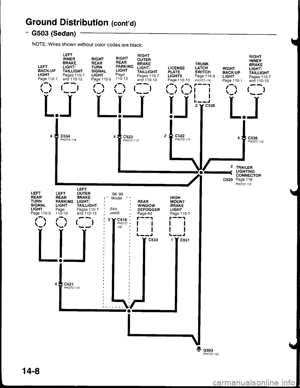
Ground Distributioh (cont'd)
- G503 (Sedan)
NOTE: Wkes shown without color codes are black.
LEFTIN NERBRAKELEFT LIGHT/BACK-UP TAILLIGHTLIGHT Paqes 110-7Paqe 110,1 and 110-13
r-,r ,--r\_,, r- -,
c534
L.JLIJL.J
TRAILERLIGHTINGCONNECTORPage 118
RIGHTINNERBRAKELIGHT/TAILLIGHTPages 110-7and 110-13
()
RrcHr l!-c.{r !'rqlt-
!iTfi^. iff#"" iilt[i",
b:::1,0. ii3:3 :i3::lts'
(:) (:) rllr
TRUNKLATCHswtTcHPage 114-3
tl
tl
2 Y C535
RIGHTBACK-UPLIGHTPage 110 1
/\
LEFTREARTURNSIGNALLIGHTPage 110-5
LEFTREARPARKINGLIGHTPage110-13
/\
LEFTOUTERBRAKELIGHT/TAILLIGHTPages 1'10-7and 110-13
()
'98-'�99
Model
(Notuseo)
cs22
HIGHMOUNTBRAKELIGHTPage 110-7
tl
REARwrNDowDEFOGGERPage 64
ll
14-8
Page 1457 of 1681
Cruise Control (cont'd)
- How the Circuit Works
The cruise control system uses mechanical and
electrical devices to maintain the car's soeed at a
setting selected by the driver.
System Description
The cruise control unit receives command signals
from the cruise control main switch and the cruise
control SevBesume switch. With the ignition switch
in ON (ll) or START (lll), voltage is provided to the
cruise control main switch. When you push the
switch to on, power is provided to the cruise control
unit and the brake switch.
The cruise control unit receives information about
operating conditions from the brake switch, the
ignition control module (lCM), the vehicle speed
sensor (VSS), and the clutch switch (manual
transmission) or the A,/T gear positton switch
(automatic transmission). The cruise control unit
then sends signals to the cruise conirol actuator
which regulates the throttle position to maintain the
selected speed. The control unit compares the
aclual speed of the car to the selected speed. The
control unit then uses the result of that comoarison
to oDen or close the throttle.
The brake switch releases the system's control of
the throttle at the instant you press on the brakepedal. The switch sends a signal to the control unit
by removing power from the normally closed brake
input (GRY wire), and providing power at the
normally open brake input (GRNMHT wire). The
control unit responds by allowing the throttle to
close. The clutch switch or the A/T gear position
switch sends a "disengage" signal to the control unit
that also allows the throttle to close.
The cruise control system will set and automatically
maintain any speed above 25 mph (40 km/h). To set
it, make sure the main switch is on and the switch
indicator is on. Then, after reaching the desired
speed, press the set switch. This sends a "set"
signal to the cruise control unit which, in turn,
controls the cruise control actuator to maintain the
set soeed.
When you push the SET switch and the cruise
control system is on, the "cruise control" ON
indicator lights up.
34-4
You can cancel the cruise control system by
turning the main switch off. This removes power to
the control unit and erases the set sDeed from
memory. lf the system is disengaged temporarily
by the brake switch, or clutch switch, and the car's
speed is still above 25 mph, press the RESUME
switch: the car will automatically return to the
previously set speed.
For gradual acceleration without pressing the
accelerator pedal, push the RESUME switch and
hold it there. This will send an "acceleration" signal
to the control unit. When you release the switch, the
system will be reprogrammed tor the new speed. To
slow the car down, push the SET switch in and hold
it there. This sends a "deceleration" signal to the
control unit, causing the car to coast. When the
desired speed is reached, release the SET switch.
This reprograms the system for the new speed.
Reter to the Service Manual (Section 23, Electrical)
for specific tests or troubleshooting procedures.
Page 1497 of 1681
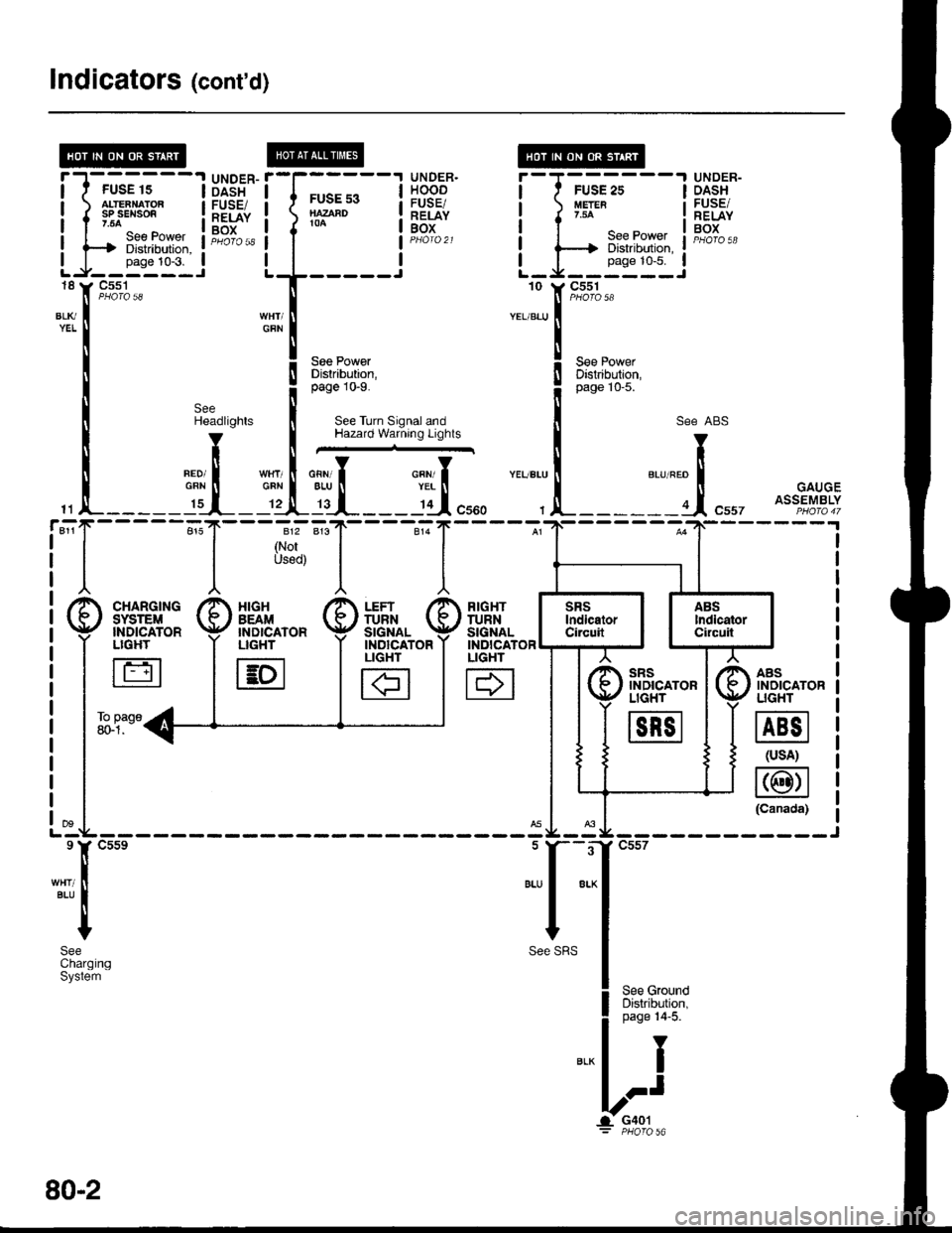
Indicators (cont'd)
@
tt
t(
tt
lt
tl
"-T
!T
!I
gI
IUNDER.HOODFUSE/RELAYBOX
UNDER-DASHFUSE/RELAYBOX
l-J-rr-trr1---l
LJi!*''i
DASHFUSE/RELAYBOX
FUSE s3NAZAAD104
18
BLl(YEL
11
811r
See PowerDistrabution,page 10-9.
See Turn Signal andHazard Warning Lights
SeeHeadlights
V
tlneoi IGRN tI._ I':r__
I
{
I
812
(NorUsod)
___l'd",,,
RIGHTTURNSIGNALINDICATORLIGHT
H
AASINOICATORUGHT
@
(usA)
@(Canada)
"..,::,f
t*'
! ,"" ro*o
il
;:i:it''l
see ABs
"r""." I "., "." trt
, !-------a.1, "uu, ott?fl%tf
sRsINDICATORLIGHT
m
XIGHBEAM'NDICATORLIGHT
E
FUSE 15ALTEANATORsP sEl{son.54
---t Diskibution, :
-rr"t:t--i'C5s1