window HONDA INTEGRA 1998 4.G Repair Manual
[x] Cancel search | Manufacturer: HONDA, Model Year: 1998, Model line: INTEGRA, Model: HONDA INTEGRA 1998 4.GPages: 1681, PDF Size: 54.22 MB
Page 1121 of 1681
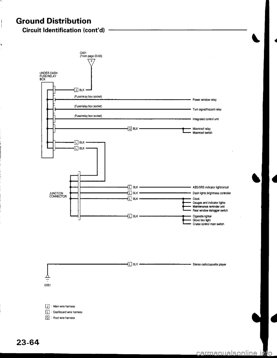
Ground Distribution
JUNCIIONCONNECTOR
U : Main wrre larness
E : oashboardwire haness
E , B*tr,it" h",n"..
Circuit ldentification (cont'dl
G40l(From page 23-63)
UNDEN.DASIFUSEi RELAYBOX
Turn sbnal/he2ad relay
hlegraled conlrol unil
BLh-Moonlmlleray- MooNool switch
BLK
BLK
8LK
ABS/SRS indicalor lighvci.dril
oash lighls brighhess clitroller
ClockGauges and indicalor lighlsMaiol€nan6 Gmind€a milR6ar window d6logger switch
A-^..'.''..'..- Cqal€nergrnet
l- Glove box lighlr- Ouise conlrol nan sw|ldr
Steleo mdio/cassello playel
G551
23-64
Page 1122 of 1681
I "tl
III
J- - - - --------- l (Haldlback)
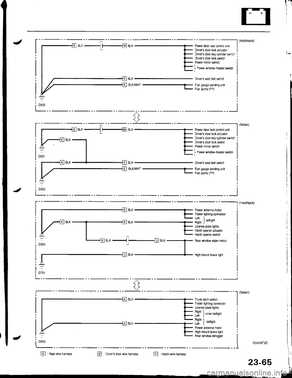
Power door oci contro unrt IDriveas door lockaclualof I;Dtlver's door key cylinder swrtclrDfveas door lock swilch
BLKMHT ---1-
I Power window masler swildl)
Dr veis seal belt swilch
Fue gauge sending lnilFue plmp (FP)
ri:
----------l (sedan)
Power dooa lock conlrol unil IDriveas door lock aclualor I
BLKWHT-
Drlver's door key cylinder swllchDrlve/s door lock swilch
I Power window masler swilch)
Dive. s seal beit swilch
Foelgaee sending unitFuelpump (FP)
i Gso2
_ _ _--_______.] {Halchback)
r- || | F T6iler tiqhxng conneclor I
lil i ,",rror,'nqfi JLicense plale lighlsHalci opener aotualorHalci opener swilch
Rear window wiper molor
High mounl hake ighl
otw ^ -n1
t-
l_:1' ^r;-"-1 7_1;.^G503
Trunk lalch swildlTf ailer light ng conneclorLicense plate lighlsRiohl I�L; J Inner larqnr
Riohl I� .Le-ft J raflqnl
High mounl brake lighlRea. window d€logger
I
""*'�
I
(cont'd)
B : R6arwire hamessM : Dver's doorwire harness@ Hatchwire harness
:
G503
23-65
Page 1126 of 1681
1
I
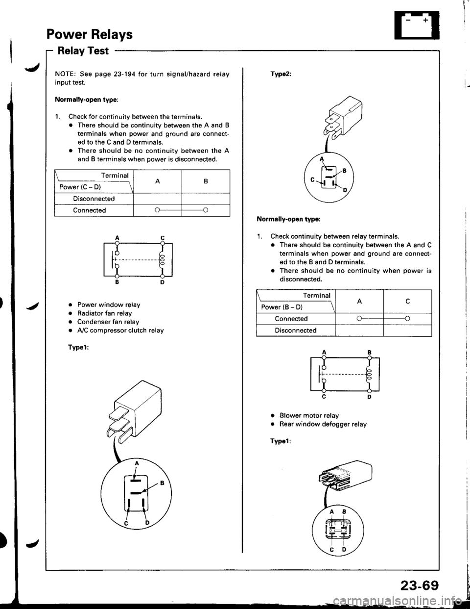
PowerRelays
RelayTest
JNOTE: See page 23-194 for turn signal/hazard relay
input test.
Normally.open type:
fWC2i
1. Check for continuitv between the terminals.
. There should be continuity between the A and B
terminals when power and ground are connect-
ed to the C and D terminals.
. There should be no continuity between the A
and B terminals when power is disconnected.
<2
F;Z
,,A
/ l'El--E \
ey
Normally-opon type:
'1. Check continuity between relay terminals.
. There should be continuity between the A and C
terminals when power and ground are connect-
ed to the B and D terminals.
o There should be no continuitv when oower is
disconnacted,
o Power window relay
. Radiator fan relay
. Condenser fan relay
. AVC compressor clutch relay
Typel:
c
I Blower motor relay
. Rear window defogger relay
Typel:
Terminal
P";(c5t--__\B
Disconnected
Connectedoo
Terminal
P"*"r(B5-lc
Connectedoo
Disconnected
Page 1209 of 1681
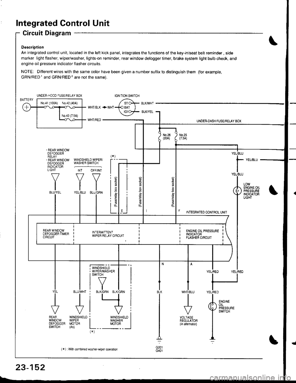
Integrated Control Unit
Circuit Diagram
Description
An integrated control unit, located in lhe left kick panel, integrates the lunctions of the key-in/seat belt r€minder , side
marker light llasher, wiper/washer, lights-on reminder, rear window delogger timer, brake system light bulb check, and
engine oil pressure indicator flasher circuits.
NOTE: Different wires with the same color have been given a nu mber suflix to distinguish them (for example,
GRN/RED I and GRN/RED'� are not the same).
REAR WINDOWDEFOGGERRELAYREAF WINDOWDEFOGGENIND CATORL GHT
f-7
IIBLU/YEL
WHT/ BLK
WHT/ REO
+WHT
WNDSHIELDWIPERiWASHER SWITCH
INT OFF/INT
f7 f7
tltlYEUBLU 8LU/GRN
BLUMHT
J
wtN0sHr€10WIPERMOTOR
UNDER.DASH FUSARETAY BOX
F rmecnlleo counoL ultr
YEUBLU
rYEUBLU
YEUREO YEUREO
tl
IYEURED
LOWENGINEOIIPRESSUREINOICATOBLIGHT
; WINDSHIELD' WIPERMASHERI swlTcH
tf7IVtlYEL
J
FEARwtN00wOEFOGGERSWITCH
WHTIBLU
J
VOTTAGEREGULATOR(ln allernatol)
BLK
G441
ENGINEolLPRESSUREswrTcH
UNDER-NOOO FUSE/RELAY BOX
1.6
:6
t;t-L
i
"'i'- 'i*-
|
I Il
I vi: WINDSHIELO II WASHEB I
L__ "oto: _ __l(*)
n
s
s
,]
23-152
(*) :Wilh combined washer-wiper operalion
Page 1212 of 1681
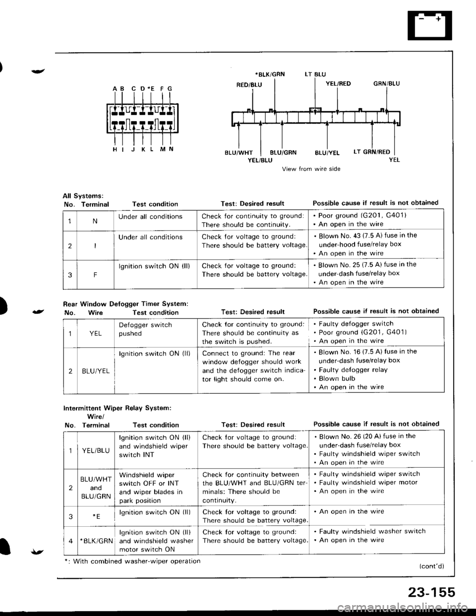
A B C D *E F G
YEL/BLU
View from wire side
All Systems:
No. TerminalTest condition
Rear Window Defogger Timel System:
No. WireTest condition
Test: Desired resultPossible cause if result is not obtained
Test: Desired resultPossible cause it lesult is not obtained
Test: Desired resultPossible cause if result is not obtained
(cont'd)
)
Inte.mittent Wiper Relay System:
Wire/
No. TerminalTest condition
*BLK/GRN
1NUnder all conditionsCheck for continuity to ground:
There should be continuity.
. Poor ground (G201, G401). An open in the wire
2
Under all conditionsCheck Jor voltage to groundl
There should be battery voltage
. Blown No. 43 (7.5 A) fuse in the
under hood fuse/relay box
'An open in the wire
3F
lgnition switch ON (ll)Check for voltage to ground:
There should be battery voltage.
. Blown No. 25 (7.5 A) fuse in the
under dash fuse/relay box
. An open in the wire
1YEL
Delogger switch
pusneo
Check for continuity to ground:
There should be continuity as
the switch is pushed.
Faulty defogger switch
Poor ground (G201, G401 )
An open in the wire
2BLU/YEL
lgnition switch ON (ll)Connect to groundr The rear
window defogger should work
and the defogger switch indica
tor light should come on.
Blown No. 16 (7.5 A) fuse in the
under-dash fuse/relay box
Faulty delogger relay
Blown bulb
An open in the wire
YEL/BLU
lgnition switch ON (ll)
and windshield wiper
switch INT
Check lor voltage to ground:
There should be battery voltage
Blown No.26 (20 Ai fuse in the
under-dash fuse/relay box
Faulty windshield wiper switch
An open in the wire
2
BLU/WHT
and
BLU/GRN
Windshield wiper
switch OFF or INT
and wiper blades in
park position
Check for continuity between
the BLU/WHT and BLU/GRN ter
minals: There should be
contrnurty.
Faulty windshield wiper switch
Faulty windshield wiper motor
An open in the wire
3lgnition switch ON (ll)Check lor voltage to ground:
There should be battery voltage
An open in the wire
*BLK/GRNlgnition switch ON (ll)
and windshield washer
motor switch ON
Check lor voltage to ground:
There should be battery voltage.
Faulty windshield washer switch
An open in the ware
v*: With combined washer-wiper oDeration
23-155
Page 1235 of 1681
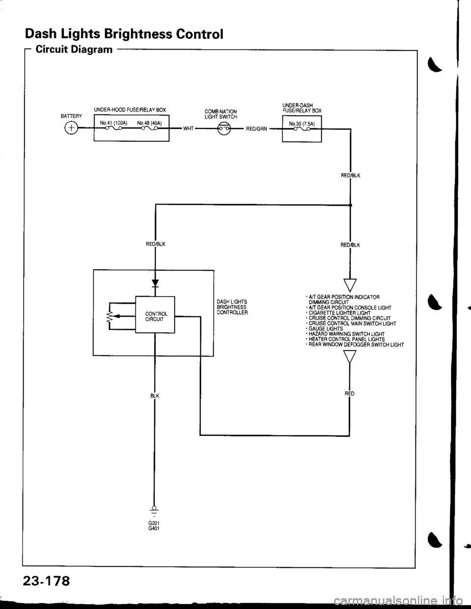
Dash Lights Brightness Control
Circuit Diagram
UNDER-HOOO FUSgRELAY 8OXUNDEN.DASHFUSE/RELAYEOXtX"f -.------^-;^*;;ilLrcrTswrc.
ffiwHT-lf-FEDGaN
, &TGEAN POSITION INOICATOROIMMING CIFCUIT.ATTGEAB POSITION CONSOLE LIGHT
. CRUISE COI,{TROL DIMMING CIRCUIT.CRUISE CONTHOT MAIN SWITCH LIGHT.GAUGE LIGHTS.HAZAFDWABN NG SWITCH LIGHT. HEATER CONTROL PANEL LIGHTS. REAR WINDOW DEFOGGER SWITCH LIGHT
23-178
Page 1248 of 1681
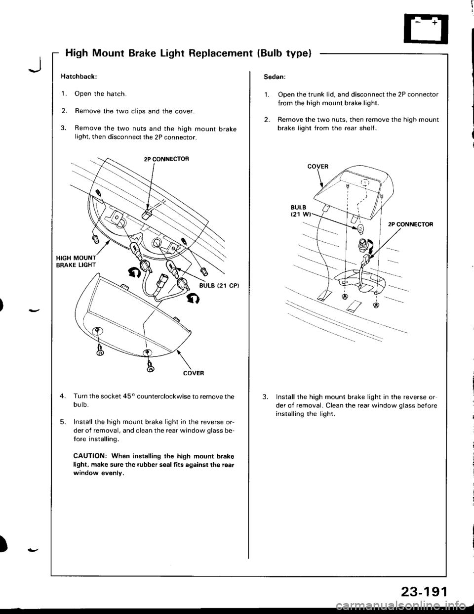
High Mount Brake Light Replacement (Bulb type)
Hatchback:Sedan:
1.Open the hatch.
Remove the two clips and the cover.
Remove the two nuts and the high mount brakelight, then disconnect the 2P connecror.
1.Open the trunk lid, and disconnect the 2P connector
from the high mount brake light.
Remove the two nuts, then remove the high mount
brake light from the rear shelt.
2.
3.
2.
2P CONNECTOR
Turn the socket 45o counterclockwise to remove the
bulb.
Install the high mount brake light in the reverse or-
der of removal, and clean the rear window glass be-
tore installing.
CAUTION: When installing the high mount brake
light, make sure the rubber seal fits against the reai
window evenly.
3.Install the high mount brake light in the reverse or
der of removal. Clean the rear window qlass belore
installing the light.
5.
)
23-191
Page 1271 of 1681
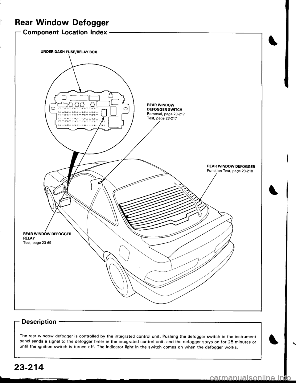
Rear Window Defogger
Component Location Index
Description
The rear window de{ogger is controlled by the integrated control unit. Pushing the detogger switch in the Instrumentpanel sends a signal to the defogger timer in the integrated control unit, and the defogger stays on for 25 minutes oruntil the ignition switch is turned off. The indicator light in the switch comes on when the defogger works.
UNDER.OASH FUSE/RELAY BOX
r-'luijij u lNEAR WINDOWDEFOGGER SWITCHRemoval, page 23-217Test, page 23 217
REARDEFOGGERREI-AYTest, page 23-69
23-214
Page 1272 of 1681
![HONDA INTEGRA 1998 4.G Repair Manual Circuit Diagram
REARwtNDowDEFOGGERSWITCH
BLK
IIJ
DASH LIGHTSBR CHTNESSCONTROLLER
CN TIONswrTcH
/ 8AT \
T ",7-l
II
II
WNT/BLK + WHT
REARWiNDOWDEFOGGER
BtK/GRN
--lELKGRN BLI(RED
1A
T L-]
ll
tl
tl
tl-l
U HONDA INTEGRA 1998 4.G Repair Manual Circuit Diagram
REARwtNDowDEFOGGERSWITCH
BLK
IIJ
DASH LIGHTSBR CHTNESSCONTROLLER
CN TIONswrTcH
/ 8AT \
T ",7-l
II
II
WNT/BLK + WHT
REARWiNDOWDEFOGGER
BtK/GRN
--lELKGRN BLI(RED
1A
T L-]
ll
tl
tl
tl-l
U](/img/13/6069/w960_6069-1271.png)
Circuit Diagram
REARwtNDowDEFOGGERSWITCH
BLK
IIJ
DASH LIGHTSBR CHTNESSCONTROLLER
CN TIONswrTcH
/ 8AT \
T ",7-l
II
II
WNT/BLK + WHT
REARWiNDOWDEFOGGER
BtK/GRN
--lELKGRN BLI(RED
1A
T L-]
ll
tl
tl
tl-l
UNDEF HOOD FUSE/RELAY BOX
No41 (100A) N0.42 (40A)
G201G401G201G40lHatchback:G771Sedan iG503I
23-215
Page 1273 of 1681
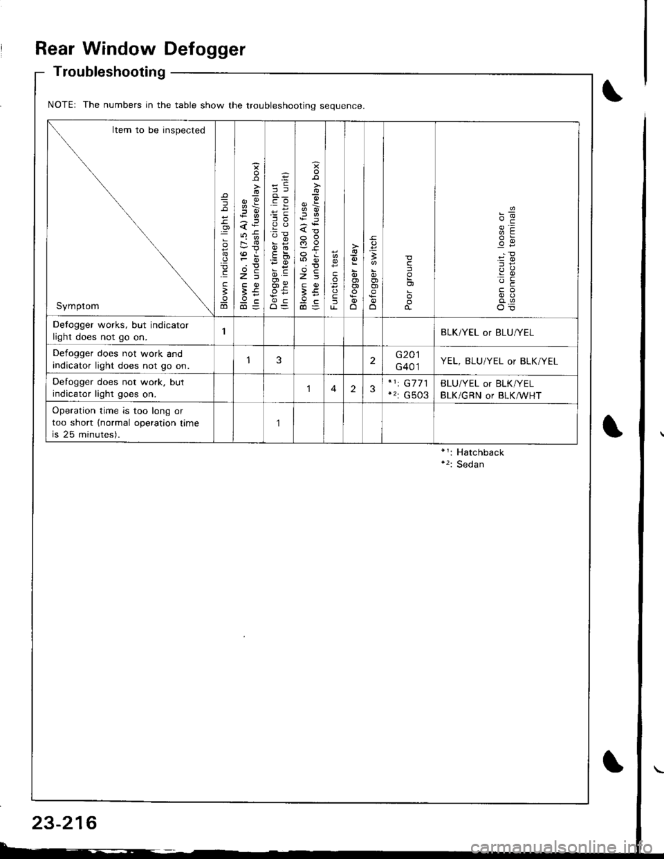
Rear Window Defogger
Troubleshooting
NOTEr The numbers in the table show the troubleshootino seouence
Item to be inspected
Symptom
=
o
.9
.E
;
ao
o
s
;!i6
<:
FO
>=
;€9c
';i !
oi
O=
{o
a5
3tr
ta
fu-o
,
OJo)
o
c
'-c
Defogger works, but indicator
light does not go on.BLK/YEL or BLU/YEL
Defogger does not work and
indicator light does not go on.3G201
G401YEL, BLU/YEL or BLK/YEL
Defogger does not work, but
indicator light goes on.123G7 71
G503
BLU/YEL or BLK/YEL
BLK/GRN or BLK/WHT
Operation time is too long or
too short (normal operation time
is 25 minutes).
,]
23-216