torque HONDA INTEGRA 1998 4.G Workshop Manual
[x] Cancel search | Manufacturer: HONDA, Model Year: 1998, Model line: INTEGRA, Model: HONDA INTEGRA 1998 4.GPages: 1681, PDF Size: 54.22 MB
Page 43 of 1681
\-a
Engine Removal/lnstallation
Speciaf Tools .......... ...........5-2
Engine RemovaUlnstallation ................ 5-3
Mount/Bracket Torque .... 5-17
)
Page 62 of 1681
I
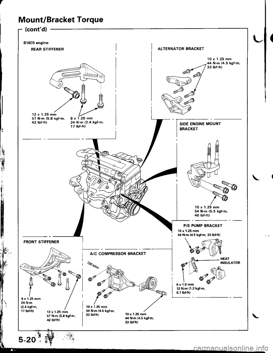
Mount/Bracket Torque
(cont'dl
818C5 engine:
REAR STIFFENER
(
ALTERNATOR BRACKET
10 r 1.25 mm
12 x 1.25 mm57 N.m {5.8 kgf.m,42 tbt'trt24 N.m 12.4 kgl.m,17 rbf'ftt
--q;;/44N'mtr.5kst'm'v=ahp /
w#
q7
10 x 1.25 mm54 N.m 15.5 kgf.m.40 rbt.frl
P/S PUMP BRACKET
10 x 1.25 mm
t:
ltri
rH
{ir
I\
; /r/r N.m {4.5 kgf.m, 33 lbtftl
FRONT STIFFENER
A/C COMPRESSOR BRACKET
I x'1.25 mm24 N.m(2.4 kgf'm,17 rbf.ft)12 x 1.25 mm57 N.m 15.8 kgt.m,42 lbf.ftt
6\--- HEAr
d'1N ^rNsuLAroR
I --H Gh\
"
*o-r$l/
sxrlomm v
12 N.m 11.2 kgf.m.8.7 tbf.ftt
Page 65 of 1681
r.lJ
Valve Clearance
Adjustment
NOTE:
. Valves should be adjusted cold; at a cylinder head
temperature of less than 100'F (38"C).
Adjustment is the same for both intake and exhaust
valves.
. After adjusting, retorque the crankshaft pulley bolt to
177 N.m (18.0 kgf.m, 130 lbf'ft).
1. Remove cylinder head cover.
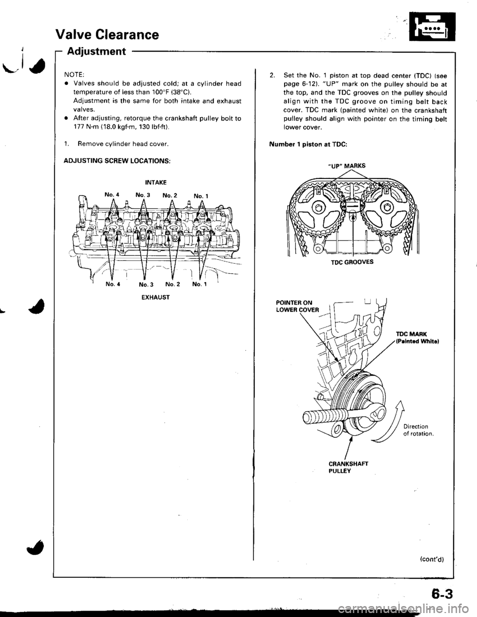
ADJUSTING SCREW LOCATIONS:
EXHAUST
(
"UP" MARKS
TDC GBOOVES
2. Set the No. 1 piston at top dead center (TDC) (see
page 6-12). "UP" mark on the pulley should be at
the top, and the TDC grooves on the pulley should
align with the TDC groove on timing belt back
cover. TDC mark (painted white) on the crankshaftpulley should align with pointer on the timing belt
lower cover.
Number 1 piston at TDC:
POINTER ONLOWER
TDC MAFK(P.inted whh.l
(cont'd)
6-3
Page 70 of 1681
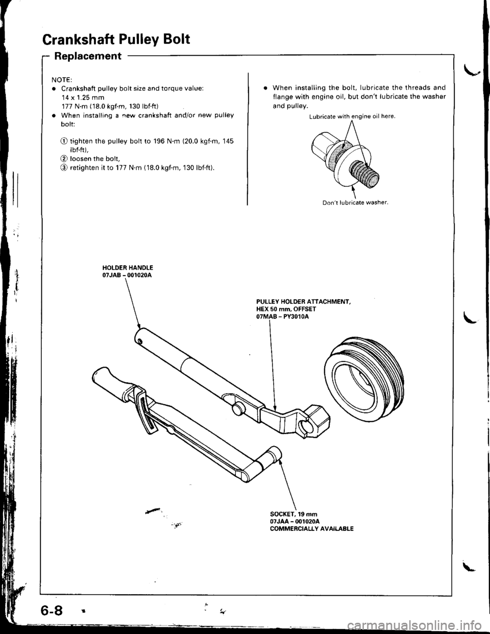
Grankshaft Pulley Bolt
Replacement
NOTE:
o Crankshaft pulley bolt size and torque value:'14 x 1.25 mm
177 N.m (18.0 kgf m, 130 lbtft)
a When installing a new crankshaft and/or new pulley
bolt:
O tighten the pulley bolt to 196 N.m (20.0 kgim, 145
lbf.ft),
@ loosen the bolt,
o retighten it to 177 N.m (18.0 kgf.m, 130 lbift).
When installing the bolt, lubricate the threads and
flange with engine oil, but don't lubricate the washer
and DUllev.
Don't lubricate washer.
PULLEY HOLDEB ATTACHMENI,HEX 50 mm, OFFSETOTMAB - PY3O1OA
SOCKET, 19 mm07JAA - @1020ACOMMERCIALLY AVAILABLE
\-
Page 71 of 1681
\-a
I
I
{
. 6-9
Timing Belt
Inspection
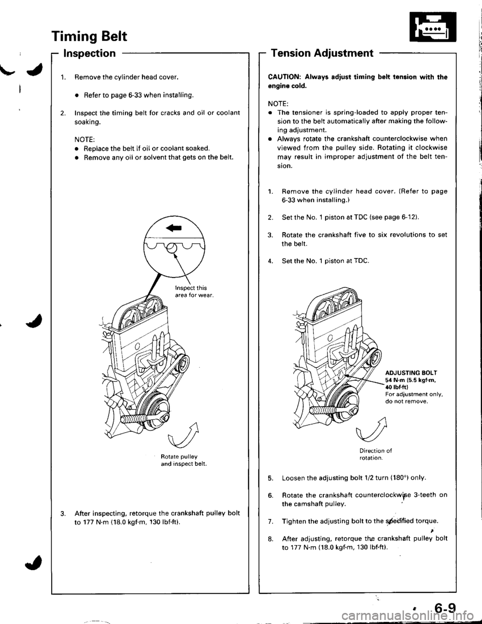
1.Remove the cylinder head cover.
o Refer to page 6-33 when installing.
Inspect the timing belt for cracks and oil or coolant
soal(n9.
NOTE:
. Replace the belt if oil or coolant soaked.
. Remove any oil or solvent that gets on the belt.
2.
Rotate pulley
and inspect belt.
After inspecting. retorque the crankshaft pulley bolt
to 177 N'm (18.0 kgf.m, 130 lbnft).
CAUTION: Always adiust iiming belt lension with the
engin€ cold.
NOTE:
. The tensioner is spring-loaded to apply proper ten-
sion to the belt automatically after making the follow-
ing adjustment.
. Alwavs rotate the crankshaft counterclockwise when
viewed from the pulley side. Rotating it clockwise
may result in improper adjustment of the belt ten-
ston.
Remove the cylinder head cover. (Refer to page
6-33 when installing.)
Set the No. I piston at TDC (see page 6-12).
Rotate the crankshaft five to six revolutions to set
the belt.
Set the No. 1 piston at TDC.
1.
2.
ADJUSTING BOLT54 N.m (5.5 kgf.m,{0 rbr.fttFor adjustment only,do not remove,
7.
8.
Direction ofrotation.
Loosen the adjusting bolt 1/2 turn (180') only.
Rotate the crankshaft counterclockwiFe 3-teeth on
the camshaft pulley
Tighten the adjusting bolt to the qdebified torque.
After adjusting. retorque the crankshaft pulley bolt
to 177 N.m {18.0 kgf.m, 130 lbf.ftl.
Page 94 of 1681
Cylinder Head
Installation (cont'dl
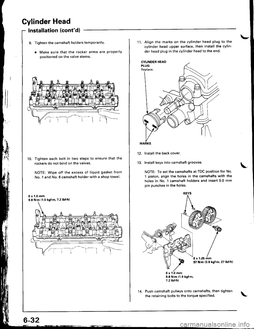
9, Tighten the camshaft holders temporarily.
a Make sure that the rocker arms are properly
positioned on the valve stems
10. Tighten each bolt in two steps to ensure that the
rockers do not bind on the valves.
NOTE: wipe off the excess of liquid gasket from
No. 1 and No. 6 camshaft holder with a shop towel
6x1.0mm9,8 N.m 11.0 kgf m, 7.2 lbt'ftl
\-
11. Align the marks on the cylinder head plug to the
cylinder head upper surface, then install the cylin-
der head plug in the cylinder head to the end.
CYLINDEB HEADPLUGReplace.
13.
lnstall the back cover.
Install keys into camshaft grooves.
NOTE: To set the camshafts at TDC position for No.
1 piston, align the holes in the camshafts with the
holes in No. 1 camshsft holders snd insert 5.0 mm
pin punches in the holes.
8 x 1.25 mmt7 N.|rl {3.8 kst.m,27 lbf.ftl
6x1.0mm9.8 N.m {1.0 kgt m.7.2 tbr.ft)
Push camshaft pulleys onto camshafts, then tighten
the retaining bolts to the torque specified.
KEYS
14.
Page 147 of 1681
I
lllustrated Index
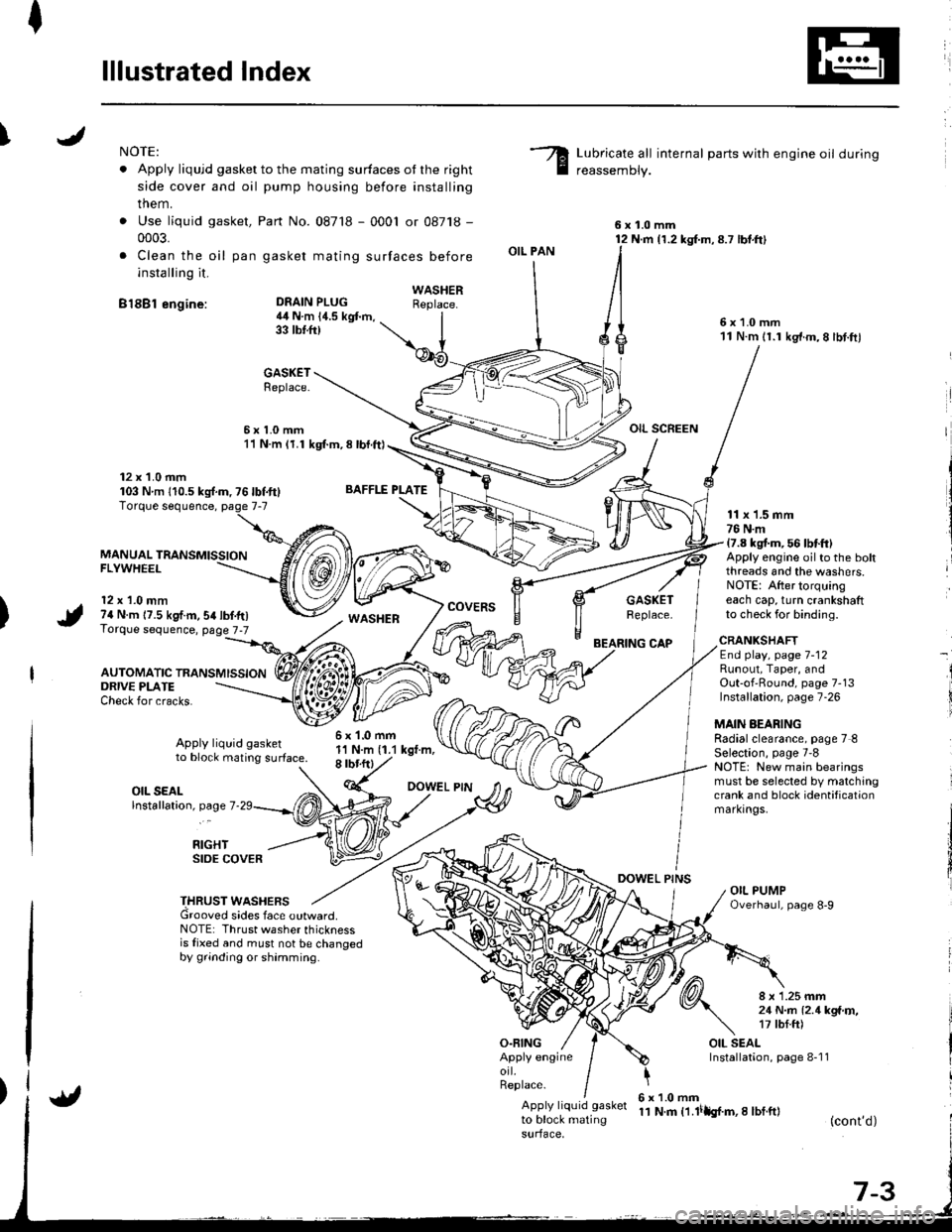
INOTE:
. Apply liqujd gasket to the mating surfaces ot the right
side cover and oil pump housing before installing
them.
. Use liquid gasket,
0003.
. Clea n the oil pan
installing it.
B18Bl engine:
Part No. 087'18 - 0001 or 08718 -
gasket mating surfaces before
Lubricate all internal parts with engine oil during
reassemDly.
6x1.0mm12 N.m {1.2 kg{.m,8.7 lbt.ft}
6x1.0mm11 N.m 11.1 kg'f.m,8 lbt.ftl
OIL SCREEN
DEAIN PLUG4il N.m 14.5 kgt m,33 tbtft)
BAFFLE PLATE
6x1.0mm1'l N.m (1.1 kgt.m,8 rbr.ftl
OIL PAN
O.FING
CAP
DOWEL PINS
WASHERReplace.
GASKETReplace.
6x1.0mm11 N.m (1.1 kgl.m, 8 lbl.ft)
12 x 1.0 mm103 Nm 110.5ks{.m,76lbf.ft}
MANUAL TRANSMISSIONFLYWHEEL
12 x 1.0 mm74 N.m 17.5 kgf.m,54lbf.tr)Torque sequence, page 7-7
AUTOMATIC TRANSMISSION
WASHERcovERsGASKETReplace.
11 x 1.5 mm76 N.m17.8 kgt m, 56 lbtft)Apply engine oilto the boltthreads and the washers.NOTE: After torquingeach cap, turn crankshaftto check for binding.
ORIVE PLATECheck for cracks.
Apply liquid gasketto block mating surface.
CRANKSHAFTEnd play, page 7-12Runout, Taper, andOut-of'Round, page 7-13Installation, page 7-26
MAIN AEARINGRadialclearance, page 7 8Selection, page 7'8NOTE: New main bearingsmust be selected by matchingcrank and block identificationmarkrngs.
I
i
OIL SEALlnstallation, page 7
RIGHTSIDE COVER
THRUST WASHERSGrooved sides face outward.NOTE: Thrust washer thicknessis fixed and must not be changedby grinding or shamming.
8 x 1.25 mm21 N..n l2.1kga'r,�,17 tbf.ft)
OIL SEALInstallation, page 8-1 1Apply engineorl.Replace.
Apply liquid gasket
to block matingsurface,
6x1.0mm11 N.m t1.lilh{.m,I lbf.ft}(cont'd)
Page 152 of 1681
/
li
l
Main Bearings
Clearance
2.
3.
1.
4.
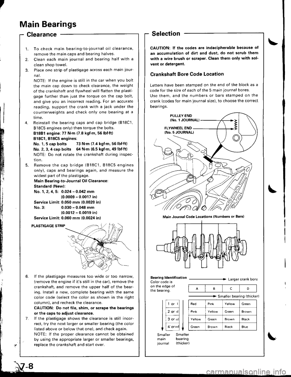
To check main bearing-to-iournal oil clearance,
remove the main caps and bearing halves.
Clean each main iournal and bearing half with a
clean shop towel.
Place one strip of plastigage across each main iour-
na l-
NOTE: lf the engine is still in the car when you bolt
the main cap down to check clearance, the weight
of the crankshaft and flywheel will flatten the plasti'
gage further than just the torque on the cap bolt,
and give you an incorrect reading. For an accurate
reading, support the crank with a jack under the
counterweights and check only one bearing at a
trme.
Reinstall the bearing caps and cap bridge (B18C1,
B18C5 engines only)then torque the bolts.
Bl8Bl engine: 77 N'm (7.8 kgt.m.56lbf.ft)
B18Cl,818C5 engines:
No. 1,5 cap bolts 73 N.m (7.4 kgf.m,56lbnftl
No. 2. 3, 4 cap bolts 64 N.m {6.5 kgf m. 49 lbf ftl
NOTE: Do not rotate the crankshaft during inspec-
tro n.
Remove the cap bridge (818C1, 818C5 engines
only), caps and bearings again, and measure the
widest part of the plastigage.
Main Bearing-to-Journal Oil Clearance:
Standard lNew):
No. 1, 2, 4, 5: 0.024 - 0.042 mm
10.0009 -0.0017 in)
Service Limit:0.050 mm (0.0020 in)
No.3:0.030 - 0.048 mm
10.0012 - 0.0019 inl
Service Limit:0.060 mm {0.0024 inl
PLASTIGAGE STRIP
lf the plastigage measures too wide or too narrow,
{remove the engine if it's still in the car), remove the
crankshaft, and remove the upper half of the bear-
ing. lnstall a new, complete bearing with the same
color code (select the color as shown in the right
column), and recheck the clearance.
CAUTION: Do not file, shim. or scrape the bearings
or the caps to adiust clearance.
lf the plastigage shows the clearance is still incor-
rect, try the next larger or smaller bearing (the color
listed above or below that one), and check again.
NOTE: lf the oroDer clearance cannot be obtained
by using the appropriate larger or smaller bearings.
reolace the crankshaft and start over.
Selection
CAUTION: lf the codes ale indecipherable because of
an accumulation oI dirt and dust, do not scrub them
with a wire bru6h or scraper. Clean lhem only with sol-
vent or detergent.
Crankshaft Bore Code Location
Letters have been stamped on the end of the block as a
code for the size of each of the 5 main iournal bores
Use them, and the numbers or bars stamped on the
crank {codes for main journal size), to choose the correct
Dean nqs,
FLYWHEEL END
Main JouhalCode Locations (Numbe.s or Bars)
Bearing ldentif ic.tionColor code ison the edge ofthe bearing.
Larger crank bore
acD
"""""""" Smallerbearingithicker)
Green
Elack
B'ownBlackElue
Smaller Smallermain bearingjournal lthacker)
Page 153 of 1681
I
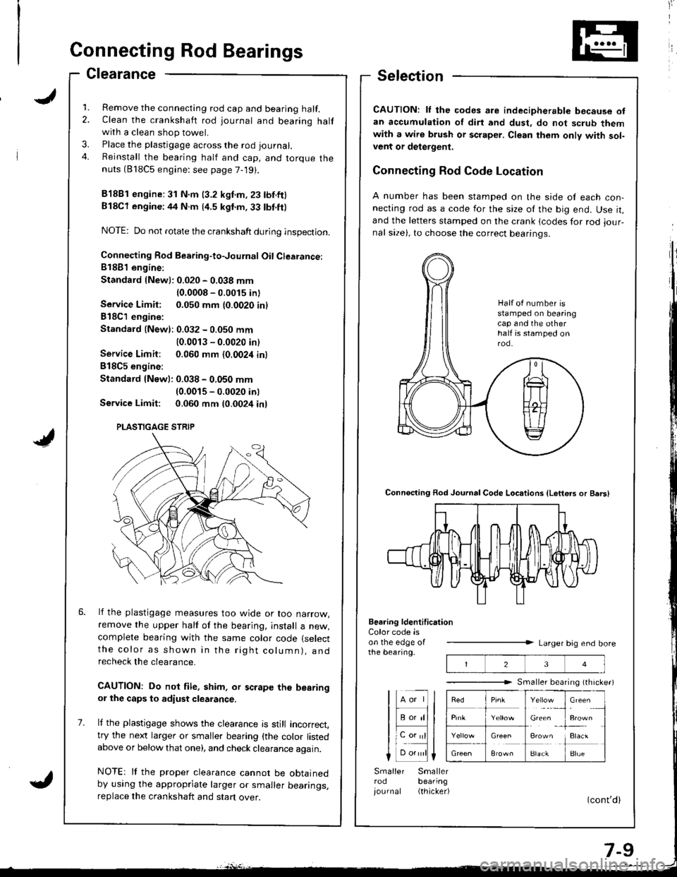
IConnecting Rod Bearings
Clearance
1. Remove the connecting rod cap and bearing half.2. Clean the crankshaft rod journal and bearing halfwith a clean shop towel.
3. Place the plastigage across the rod journal.
4. Reinstall the bearing half and cap, and torque thenuts (818C5 engine: see page 7-19).
81881 engine:31 N.m (3.2 kgnm,23 tbf.ftl
Bl8Cl engine:44 N.m (4.5 kgl.m.33 tbl.ft)
NOTE: Do not rotate the crankshaft during inspection.
Connecting Rod Bearing-to-Journal Oil Clearance:81881 engine:
Standard {Newl: 0.020 - 0.038 mm
{0.0008 - 0.0015 inl
Service Limit: 0.050 mm {0.0020 inl
818C1 engine:
Standald {Newl: 0.032 - 0.050 mm
10.0013 - 0.0020 in)
Service Limit: 0.060 mm {0.0024 in}
B18C5 engine:
Standard lNew): 0.038 - 0.050 mm(0.0015 - 0.0020 inl
Service Limit: 0.060 mm t0.0024 inl
lf the plastigage measures too wjde or too narrow,remove the upper half of the bearjng, install a new,complete bearing with the same color code (select
the color as shown in the rig ht column), andrecheck the clearance.
CAUTION: Do not file, shim, or scrape the bearingor the caps to adiust clearance.
It the plastigage shows the clearance is still incorrect,try the next larger or smaller bearing (the color listedabove or below that one), and check clearance again.
NOTEr It the proper clearance cannot be obtainedby using the appropriate larger or smaller bearings,replace the crankshaft and stan over.
Selection
CAUTION: lf the codes are indecipherable because ofan accumulation of dirt and dust, do not scrub themwith a wire brush or scraper. Clean them only with sol-vent or delergent.
Connecting Rod Code Location
A number has been stamped on the side of each con-necting rod as a code for the size of the big end. Use it,and the letters stamped on the crank lcodes for rod iour-nal size), to choose the correct bearinqs.
Connecting Rod Journal Code Loc.tions {Letters or Bers)
Beering ldentification
23
Y"rl.:_,
Gie& ,
!**
i:1"
BlackBlue
Color code ison the edge oIthe bearing.Larger big end bore
Smaller bearing (th rche.)
lHll
I F;;lll
lL".;|l
Smaller Smallerrod bearing
iournal (thicker)
Half ot number isstamped on bearingcap and the otherhalf is stamped onrod.
PLASTIGAGE STRIP
Page 181 of 1681
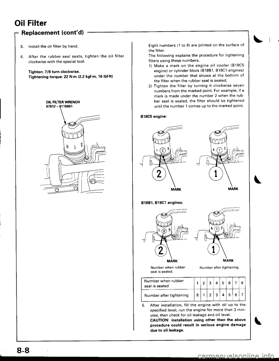
Oil Filter
Replacement (cont'd)
Install the oil filter by hand.
After the rubber seal seats, tighten the oil
clockwise with the special tool.
Tighten: 7/8 turn clockwise.
Tightening torque:22 N m (2.2 kgf m,'16 lbf ftl
tilte r
OIL FILTER WRENCH
8-8
Eight numbers (1 to 8) are printed on the surlace ol
the filter.
The lollowing explains the procedure for tightening
filters using these numbers.
1) Make a mark on the engine oil cooler (818c5
engine) or cylinder block (8188'1, 818C1 engines)
under the number that shows at the bottom of
the filter when the rubber seal is seated.
2) Tighten the filter by turning it clockwise seven
numbers Irom the marked point. For example, if a
mark is made under the number 2 when the rub
ber seal is seated, the filter should be tightened
until the number 1 comes up to the marked point
818C5 engine:
B1881, 818C1 engines:
Number when rubber
seal is seated.Number after tightening
MARK
MARK
Number when rubber
seal is seated
'I2345678
Number after tightening812561
5. After installation, fill the engine with oil up to the
specilied level, run the engine for more than 3 min-
utes, then check for oil leakage and oil level.
CAUTION: Installation using other than the above
procedure could result in serious engine damage
duo to oil leakage.