Compressor bracket HONDA INTEGRA 1998 4.G Workshop Manual
[x] Cancel search | Manufacturer: HONDA, Model Year: 1998, Model line: INTEGRA, Model: HONDA INTEGRA 1998 4.GPages: 1681, PDF Size: 54.22 MB
Page 62 of 1681
I
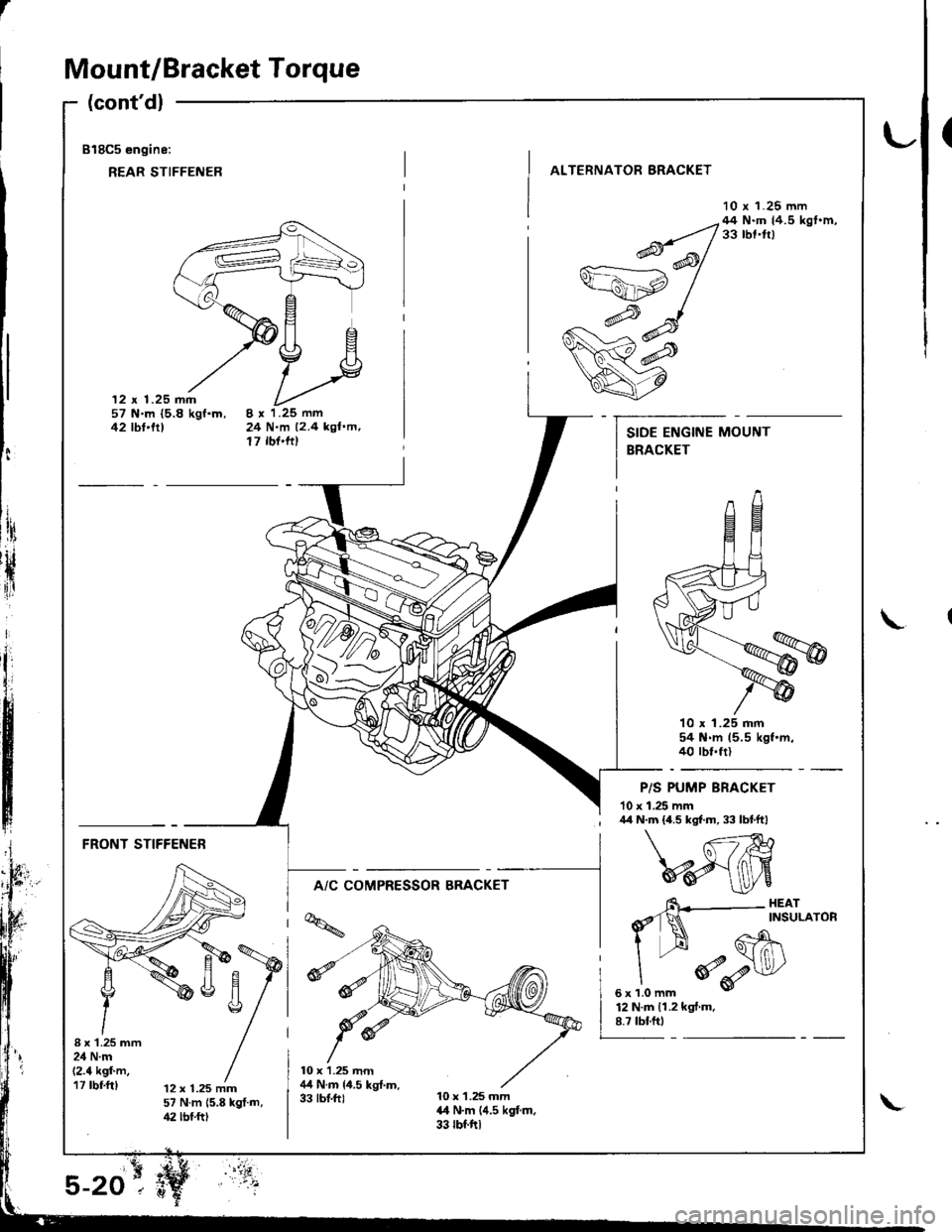
Mount/Bracket Torque
(cont'dl
818C5 engine:
REAR STIFFENER
(
ALTERNATOR BRACKET
10 r 1.25 mm
12 x 1.25 mm57 N.m {5.8 kgf.m,42 tbt'trt24 N.m 12.4 kgl.m,17 rbf'ftt
--q;;/44N'mtr.5kst'm'v=ahp /
w#
q7
10 x 1.25 mm54 N.m 15.5 kgf.m.40 rbt.frl
P/S PUMP BRACKET
10 x 1.25 mm
t:
ltri
rH
{ir
I\
; /r/r N.m {4.5 kgf.m, 33 lbtftl
FRONT STIFFENER
A/C COMPRESSOR BRACKET
I x'1.25 mm24 N.m(2.4 kgf'm,17 rbf.ft)12 x 1.25 mm57 N.m 15.8 kgt.m,42 lbf.ftt
6\--- HEAr
d'1N ^rNsuLAroR
I --H Gh\
"
*o-r$l/
sxrlomm v
12 N.m 11.2 kgf.m.8.7 tbf.ftt
Page 684 of 1681
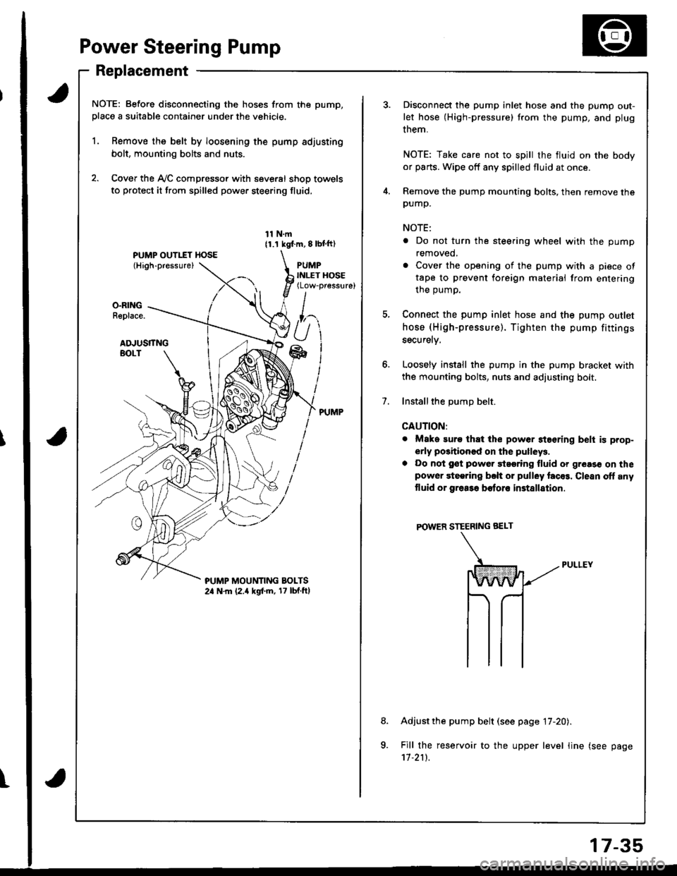
Power Steering Pump
Replacement
NOTE: Before disconnecting the hoses from the pump,
place a suitable container under the vehicle.
1. Remove the belt by loosening the pump adjusting
bolt, mounting bolts and nuts.
2. Cover the Ay'C compressor with several shop towels
to protect it from spilled power steering fluid,
11 N.m11.1 kgf.m, 8 lbl ft)
PUMPINLET HOSE(Low-pressure)
O.RINGReplace.
ADJUSTTNGBOLT
?UMP MOUt'lTlNG BOLTS2a N.m (2.a kgf.m, 17 lbf.ftl
t
7.
Disconnect the pump inlet hose and the pump out-
let hose (High-pressure) trom the pump, and plug
them.
NOTE: Take care not to spill the fluid on the body
or parts. Wipe off any spilled fluid at once.
Remove the pump mounting bolts, then remove thepump.
NOTE:
. Do not turn the steering wheel with the pump
removed,
. Cover the opening of the pump with a piece oftape to prevent foreign materiai from entering
the oumo.
Connect the pump inlet hose and the pump outlet
hose (High-pressure). Tighten the pump fittings
securelv,
Loosely install the pump in the pump bracket with
the mounting bolts, nuts and adjusting bolt.
Installthe DumD belt.
CAUTION:
. Mako suro that the power staering belt is prop-
erly positioned on the pulleys.
a Do not gst powor 9t99ring fluid or greas€ on thepower steering bclt or pulley facos. Clesn off any
tluid or grea3a botoro installation
POWER STEERING BEI-T
Adjust the pump belt (see page 17-20).
Fill the reservoir to the upper level line (see page'11.211.
8.
a
17-35
Page 1048 of 1681
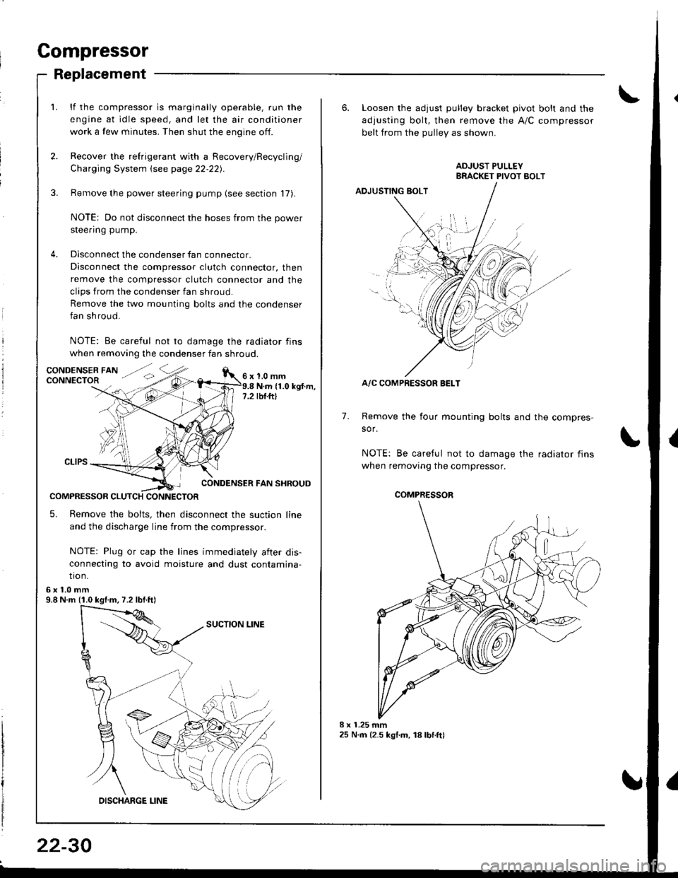
Compressor
Replacement
lf the compressor is marginally operable, run the
engine at idle speed, and let the air conditioner
work a few minutes. Then shut the engine off.
Recover the refrigerant with a Recovery/Recycling/
Charging System \see page 22-22).
Remove the power steering pump (see section 17).
NOTE: Do not disconnect the hoses from the power
steering pump.
Disconnect the condenser fan connector.
Disconnect the compressor clutch connector, then
remove the compressor clutch connector and the
clips from the condenser fan shroud
Remove the two mounting bolts and the condenser
fan shroud.
NOTE: Be careful not to damage the radiator fins
when removing the condenser fan shroud.
1.0 mmN.m (1.0 kgt.m,rbf.ftt
CONDENSER FAN SHROUD
COMPRESSOR CLUTCH CONNECTOR
5. Remove the bolts, then disconnect the suction line
and the discharge line from the compressor.
NOTE: Plug or cap the lines immediately aiter dis-
connecting to avoid moisture and dust contamina-
tio n.
6x1.0mm9.8 N.m (1.0 kgf.m, 7.2 lbf.ft)
22-30
6. Loosen the adjusl pulley bracket pivot bolt and the
adjusting bolt, then remove the A/C compressor
belt from the Dullev as shown.
ADJUSTING BOLT
A/C COMPRESSOR BELT
Remove the four mounting bolts and the compres-
sor.
NOTE: Be careful not to damage the radiator fins
when removing the compressor.
7.
./.,
COMPRESSOR
Page 1049 of 1681
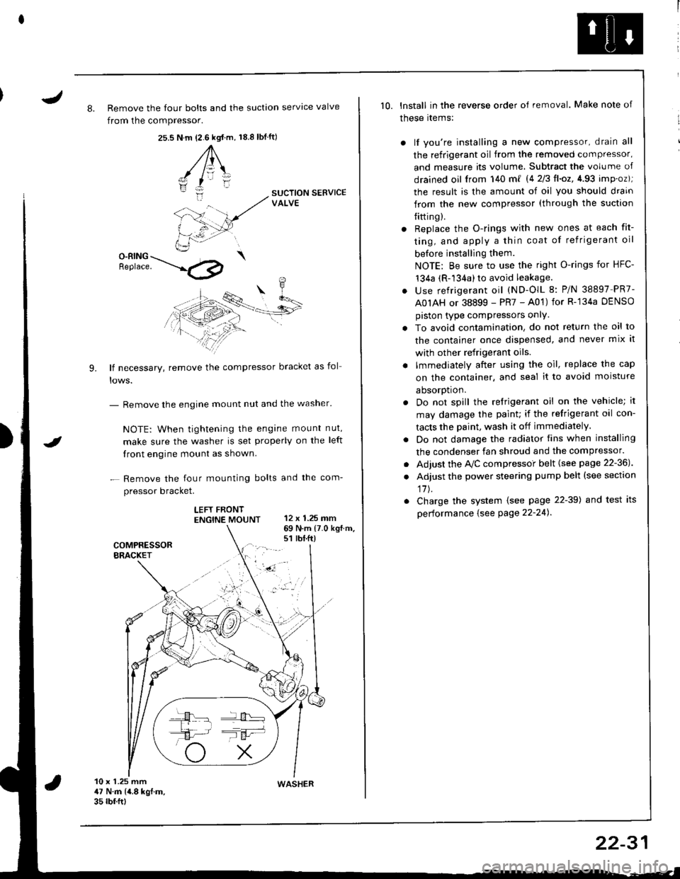
J8. Remove the four bolts and the suction servtce valve
from the compressor.
25.s18.8 tbf.ft)N.m {2.6 kgt.m,
A\
-/ l=\'zI
i:-
9.
SUCTION SERVICEVALVE
O-RING \Benrace. --'.l4p
lf necessary, remove the compressor bracket as fol
- Remove the engine mount nut and the washer'
NOTE: When tightening the engane mount nut,
make sure the washer is set properly on the left
front engine mount as shown.
- Remove the four mounting bolts and the com-
pressor bracket.
LEFT FRONTENGTNE MOUNT 12 x 1.25 mm
I
69 N.m {7.0 kg{.m.s1 rbt.ft)
10 x 1.25 mm47 N.m (4.8 kgf.m.35 rbf.ftt
10. lnstall in the reverse order of removal. Make note of
these rtems:
) lf you're installing a new compressor, drain all
the refrigerant oil from the removed compressor,
and measure its volume, Subtract the volume of
drained oil from 140 m{ 14 2/3ll.oz,4.93 imp.oz);
the result is the amount of oil you should drain
from the new compressor (through the suction
{itting).
r Replace the O-rings with new ones at each fit-
ting, and apply a thin coat of refrigerant oil
before installing them.
NOTE: Be sure to use the right O-rings for HFC-'t34a (R-134a) to avoid leakage.
. use refrigerant oil (ND-OlL 8: P/N 38897 PR7-
A0IAH or 38899 - PR7 - A01) for R-'134a DENSO
piston type compressors onlY.
. To avoid contamination, do not return the oil to
the container once dispensed, and never mix it
with other refrigerant oils.
. lmmediately after using the oil, replace the cap
on the container, and seal it to avoid moisture
aDsorDt|on.
. Do not spill the refrigerant oil on the vehicle; it
may damage the paint; if the refrigerant oil con-
tacts the Daint, wash it off immediately.
. Do not damage the radiator fins when installing
the condenser fan shroud and the compressor.
. Adjust the Ay'C compressoi belt {see page 22-36J
. Adjust the power steering pump belt (see section
17J.
. Charge the system (see page 22-39) and test its
performance {see Page 22-24).
WASHER
22-31
Page 1053 of 1681
J
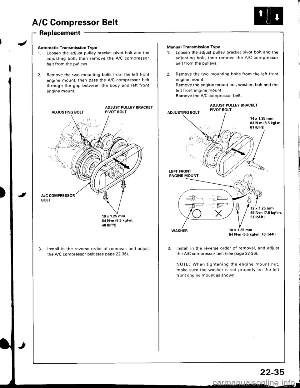
A/G Compressor Belt
Replacement
Automatic Transmission Type
1. Loosen the adjust pulley bracket pivot bolt and the
adjusting bolt. then remove the A/C compressor
belt from the Dullevs.
2. Remove the two mounting bolts from the left front
engine mount, then pass the A,/C compressor belt
through the gap between the body and left front
engrne mount.
ADJUSTING BOLT
ADJUST PULLEY BRACKETPIVOT BOLT
'10 x 1.25 mm54 N.m {5.5 kgl m,
40 rbtftl
Install in the reverse order of removal, and
the Ay'C compressor belt (see page 22 36).
aoJUsI
ll
Manual Transmission Type
1. Loosen the adjust pulley bracket pivot bolt and the
adjusting bolt, then remove the A/C compressor
belt from the pulleys.
2. Remove the two mounting bolts from the left front
engrne mount.
Remove the engine mount nut, washer, bolt and the
left front engine mount.
Remove the !i/C compressor belt.
ADJUST PULLEY BRACKETPIVOT BOLTAOJUSTING BOLT
14 x 1.25 mm83 N.m {8.5 kgl.m,61 rbf.ft)
LEFT FRONTENGINE MOUNT
wasHEB lu x l.z5 mm54 N.m (5.5 kgl m, 40lbtft)
3. Instali in the reverse order of removal, and adjust
the A,/C compressor belt (see page 22 36i.
NOTE: When tightening the engine mount nut,
make sure the washer is set properly on the left
front engine mount as shown.
T':
22-35
Page 1054 of 1681
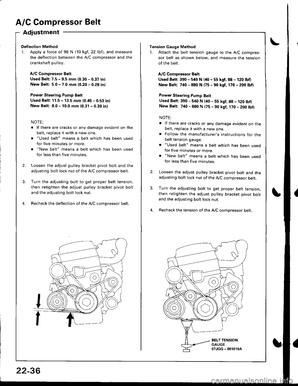
A/C Compressor Belt
Adiustment
Dellection Method
1. Apply a force of 98 N i10 kgf, 22 lbf), and measure
the deflection between the A,/C compressor and the
crankshaft pullev.
A/C Compressor Belt
Used Belt: 7.5 - 9.5 mm (0.30 - 0.37 in)
New Beli: 5.0 - 7.0 mm (0.20 - 0.28 in)
Power Steering Pump Belt
Used Bslt: 11.5 - 13.5 mm (0.i15 - 0.53 in)
New Belt: 8.0 - 10.0 mm (0.31 - 0.39 in)
NOTE:
. lf there are cracks or any damage evident on the
belt, replace it with a new one.
. "Used belt" means a belt which has been used
for five minutes or more.
. "New belt" means a belt which has been used
for less than five minutes.
Loosen the adjust pulley bracket pivot bolt and the
adjusting bolt lock nut of the lVC compressor belt.
Turn the adjusting bolt to get proper belt tension,
then retighten the adjust pulley bracket pivot bolt
and the adjusting bolt lock nut.
Recheck the deflection of the Ay'C compressor belt.
22-36
Tension Gauge Method
1. Attach the belt tension gauge to the Ay'C compres-
sor belt as shown below, and measure the tension
of the belt.
A/C Comprossor Belt
Used Belt: 390 - 5/rc N (4O - 55 kgf. 88 - 120 lbf)
New Bslt: 7,10 - 880 N (75 - 90 kgf, 170 - 200 lbf)
Power Steering Pump Belt
Used Belt: 390 - 540 N (ito - 55 kgl, g8 - i20 tbtlNew Belt: 740 - 880 N (75 - 90 kgt, 170 - 200 tbtl
NOTE:
. lf there are cracks or any damage evident on thebelt, replace it with a new one.. Follow the manufacturer's instructions for thebelt tension gauge.
. "Used belt" means a belt which has been usedfor five minutes or more.. "New belt" means a belt which has been usedfor less than five minutes.
Loosen the adjust pulley bracket pivot bolt and theadjusting bolt lock nut of the A,/C compressor belt.
Turn the adjusting bolt to get proper belt tension,then retighten the adjust pulley bracket pivot boltand the adjusting bolt lock nut.
Recheck the tension of the A,/C compressor belt.
3.
BELT TENSIONGAUGE07JGG - 0010'l0a