Obd HONDA INTEGRA 1998 4.G Workshop Manual
[x] Cancel search | Manufacturer: HONDA, Model Year: 1998, Model line: INTEGRA, Model: HONDA INTEGRA 1998 4.GPages: 1681, PDF Size: 54.22 MB
Page 237 of 1681
t-
il
Troubleshooting ".
Troubleshooting Proccdures
How To Begin Troubleshooting
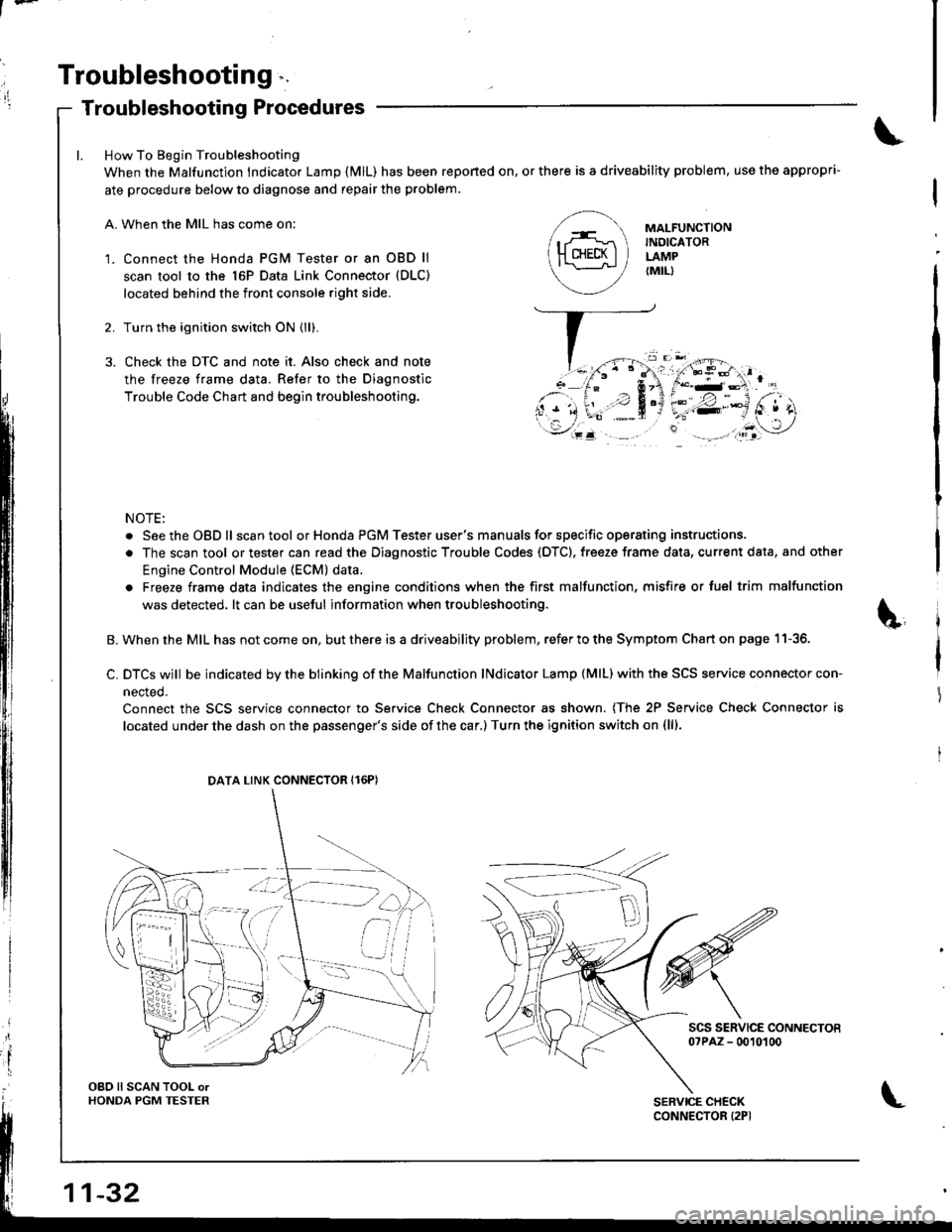
When the Malfunction lndicator Lamp {MlL) has been reponed on, or there is a driveability problem, use the appropri-
ate procedure below to diagnose and repair the problem.
A. When the MIL has come on:
'1. Connect the Honda PGM Tester or an OBD ll
scan tool to the 16P Data Link Connector (DLC)
located behind the front console right side.
2. Turn the ignition switch ON (ll).
3. Check the DTC and note it. Also check and note
the freeze frame data. Refer to the Diagnostic
Trouble Code Chart and begin troubleshooting.
NOTE:
. SeetheOBDll scantool or Honda PGM Tester user's manuals for specific operating instructions.
. The scan tool or tester can read the Diagnostic Trouble Codes (OTC). freeze frame data, current data, and other
Engine Control Module (ECM) data.
. Freeze frame data indicates the engine conditions when the first malfunction, misfire or luel trim malfunction
was detected. lt can be useful information when troubleshooting.
B. When the MIL has not come on, but there is a driveability problem, refer to the Symptom Chart on page 11-36.
C. DTCS wjll be indicated by the blinking of the Malfunction lNdicator Lamp {MlL) with the SCS service connector con-
nected.
Connect the SCS service connector to Service Check Connector as shown. (The 2P Service Check Connector is
located under the dash on the passenger's side of the car,) Turn the ignition switch on (lll.
scs sERvlcE coNNEcToEo?PAZ - 0010100
MAI-FUNCTIONINDICATORLAMP{MIL)
DATA LINK CONNECTOR Il6PI
OBO ll SCAN TOOL orHONDA PGM TESTER
Page 238 of 1681
Engine Control Module (ECM) Reset Procedure
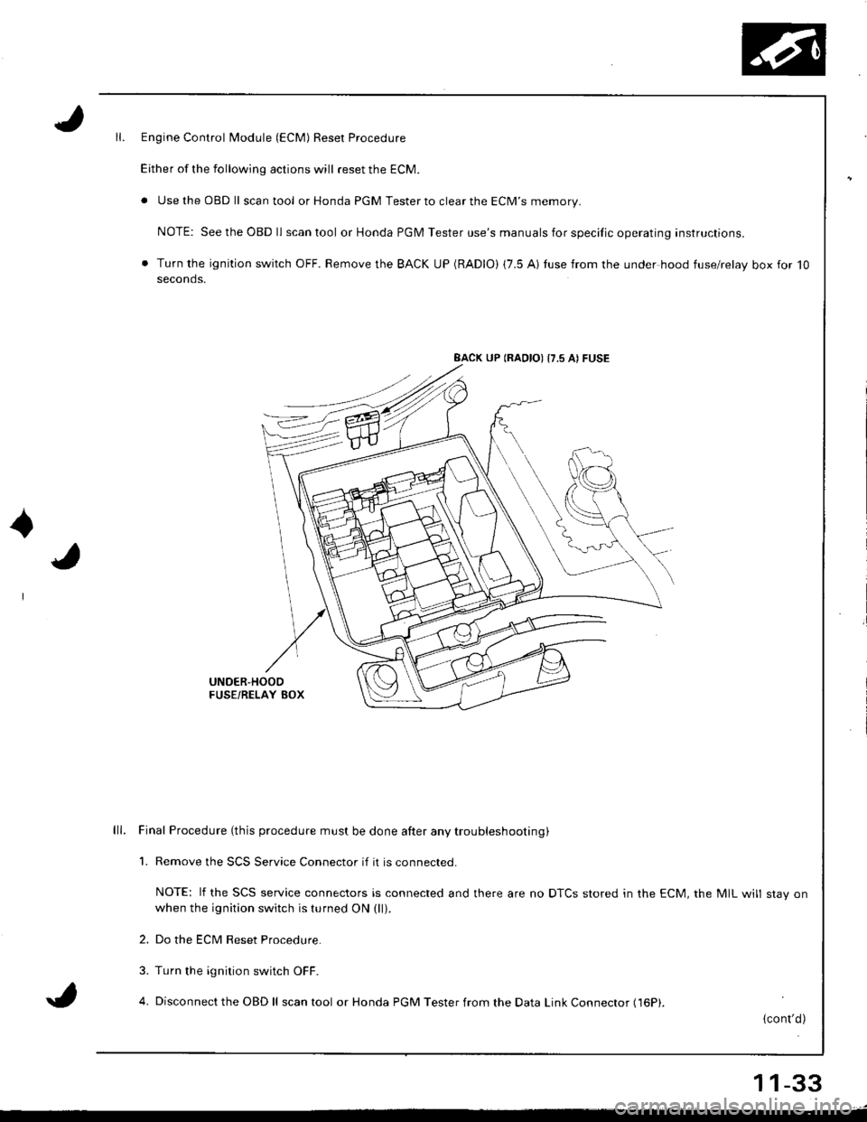
Either of the following actions will reset the ECM.
. Use the OBD ll scantool or Honda PGM Tester to clear the ECM'S memory.
NOTE: See the OBD ll scan tool or Honda PGM Tester use's manuals for specific operating instructions.
. Turn the ignition switch OFF. Remove the BACK UP (RADIO) (7.5 AI tuse from the under hood fuse/relay box for 10seconds.
BACK UP (RAOIO) {7.5 AI FUSE
UNDER'HOODFUSE/RELAY BOX
lll. Final Procedure (this procedure must be done after any trou bleshooting )
1. Remove the SCS Service Connector if it is connected.
NOTE: lf the SCS service connectors is connected and there are no DTCS stored in the ECM, the MIL will stav onwhen the ignition switch is turned ON (ll).
2. Do the ECM Reset Procedure.
3. Turn the ignition switch OFF.
4. Disconnect the OBD ll scan tool or Honda PGM Tester from the Data Link Connector (16P|.
{cont'd)
11-33
Page 242 of 1681
ECM Data
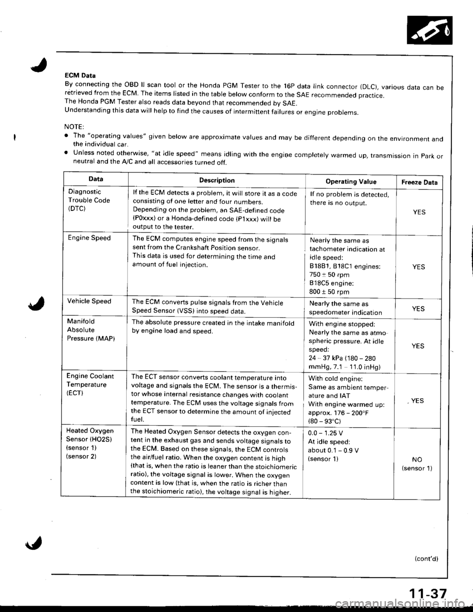
By connecting the OBD ll scan tool or the Honda PGM Tester to the 16P data link connector (DLC), various data can beretrieved from the EcM The items risted in the tabre berow conform to the sAE recommended practice.The Honda PGM Tester also reads data beyond that recommended bv SAE.understanding this data wirl herp to rind the causes of intermiftent fairures or engine probrems.
NOTE:
' The "operatlng values" given below are approximate values and may be different depending on the environment andthe individual car.' Unless noted otherwise, "at idle speed" means idling with the engiFe completely warmed up, transmissron in park orneutral and the A,/C and all accessories turned off.
DataDescriptionOperating ValueFreeze Data
Diagnostic
Trouble Code(DTC)
lf the ECM detects a problem, it will store tt as a cocteconsisting ot one letter and four numbers.Depending on the problem, an SAE-defined code{Poxxx) or a Honda-defined code (plxxx) will beoutput to the lester.
lf no problem is detected,
there is no output.
YES
Engine SpeedThe ECM computes engine speed from the signalssent from the Crankshaft Position sensor.This data is used for determining the I|me andamount of fuel injection.
Nearly the same as
tachometer indication at
idle speed:
81881,818C1 engines:
750 t 50 rpm
818C5 engine:
800 1 50 rpm
YES
Vehicle SpeedThe ECM converts pulse signals trom the VehicleSpeed Sensor (VSS) into speed data.
Nearly the same as
speedometer indicationYES
Manitold
Absolute
Pressure {MAP)
The absolute pressure created in the intake manifoldby engine load and speed.With engine stopped:
Nearly the same as atmo
spheric pressure. At idle
speed:
24 - 37 kPa (180 - 280
mmHg,7.1 1'1.0 inHg)
YES
Engine Coolant
Temperature
(ECT)
The ECT sensor converts coolant temperature intovoltage and signals the ECM. The sensor is a thermis-tor whose internal resistance changes with coolanttemperature. The ECM uses the voltage signals fromlhe ECT sensor to determine the amount of iniectedfuel.
With cold engine:
Same as ambient temper
ature and IAT
With engine warmed up:
approx. 176 - 200'F
{80 - 93.C)
, YES
Heated Oxygen
Sensor (HO2S)
{sensor 1)(sensor 2)
The Heated Oxygen Sensor detects the oxygen con-tent in the exhaust gas and sends voltage signals tothe ECM. Based on these signals,lhe ECM controlsthe airlfuel ratio. When the oxygen content is high{that is, when the ratio is leaner than the stoichiomericratio), the voltage signal is lower. When the oxygencontent is low (that is, when the ratio is richer thanthe stoichiomeric ratio), the voltage signal is higher.
0.0 - 1.25 V
At idle speed:
abour 0.'1 - 0.9 V(sensor I )NO(sensor 1)
(conl'd)
11-37
Page 245 of 1681
I
t
h,,l,!
il
Troubleshooting
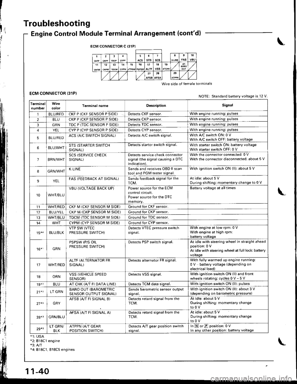
ECM CONNECTOR {31P)
Engine Control Module Terminal Arrangement (cont'd)
ECM CONNECTOR C {31P)
235srsscs1112t31515t71A19
2A
Wire side of lemale terminals
NOTE: Standard battery voltage is 12 V.
TerminalnumbercolorTerminal namoD6scriptionSignal
1BLU/REDCKF P (CKF SENSOR P SIDE)Detects CKF sensor.With engine running: pulses
28LUCKP P (CKP SENSOR P SIDE)Detects CKP sensor.With engine running: pulses
3GRNTDC P {TDC SENSOR P SIDE)Detects TDC sensor,With engine running: pulses
YELCYP P (CYP SENSOR P SIDE)Detects CYP sensor,With engine running: pulses
5BLU/REDACS (AJC SWITCH SIGNAL)Detects A,/C switch signal.With A,/C switch ON: 0 VWith A,/C switch OFF: battery voltage
6BLUA/VHTSTS (STARTEB SWITCHSIGNAL)
Detects starter switch signal.With staner switch ON: battery voltageWith starter switch OFF: 0 V
7BRN,AiVHTSCS (SERVICE CHECKSIGNAL)Detects service check connectorsignal (the signalcausing a DTC;ndication).
With the co n nector con nected: 0 VWath the connector disconnected: about 5 V
8GRNAVHTK LINESends and receives OBD ll scantool and PGM tester signal.With ignition switch ON (ll): about 5 V
9YELFAS lFEEDBACK AT SIGNAL)Sends feedback signal for theTCM,At idle: about 5 VDuring shifting: momenlary change to 0 V
10WHT/BLU
VBU (VOLTAGE BACK UP)Power source for the ECMcontrolcircuit,Power source for the DTC
Battery voltage at all times
t1WHT/REDCKF M (CKF SENSOR I\4 SIDE)Ground for CKF sensor.
12BLUI/E LCKP M (CKP SENSOR M SIDE)Ground for CKP sensor.
WHT/BLUTDCM (TDC SENSOR M SIDE)Ground tor TDC sensor.
14CYPM (CYP SENSOR M SIDE)Ground for CYP sensor.
15*.BLU/BLKVTP SW (VTEC
PRESSUFE SWITCH)Detects VTEC pressure switchsr9nal.
With engine at low rpm:0 VWith engine at high rpmlbattery voltaqe
161,GRN
PSPSW (P/S OILPRESSURE SWITCH)Derecls PSP switch signal.At idle with steering wheel in straight aheadpositioni 0 VAt idle with steering wheelat full lock: batteryvoltage
17WHT/REDALTF (ALTERNATOR FRSIGNAL)Detects alternator FR signal.With fully warmed up engine running:0 V battery voltage (depending onelectrical load)
18ORNVSS (VEHICLE SPEEDSENSORiDetects VSS signal.With ignition switch ON (ll) and lrontwheels rotating: cycles 0 V- 5 V
19*3BLUAT CHK (A/T FI DATA LINE)Detects TCM data signal.With ignition switch ON (ll)i pulses
21*LT GRNBARO OUT (SAROMETRIC
SENSOR OUTPUT S!GNAL)Sends barometric sensor outputsrgnal,With ignition switch ON (ll): about 3 V(depending on barometric pressure)
27 x3GRYAFSB (A"/T FI SIGNAL B)Detects retard signal from theTCM,At idle: about 5 VDuring shifting: momentary changeto0V
28+1GRN/8LUA+SA (A/T FI SIGNAL A)Detects retard signal from theTCM.At idle: about 5 VDuring shifting: momentarV changeto0V
29+3LT GRN/BLKATPPN (A/T GEARPOSITION SWITCH)Detects A,/T gear position switchsrgnal-In E orE positionr 0VIn anv other position: battery voltage
*1: USA*2:818C1 engine*3: A/T*4: 818C1, 818C5 engines
Page 256 of 1681
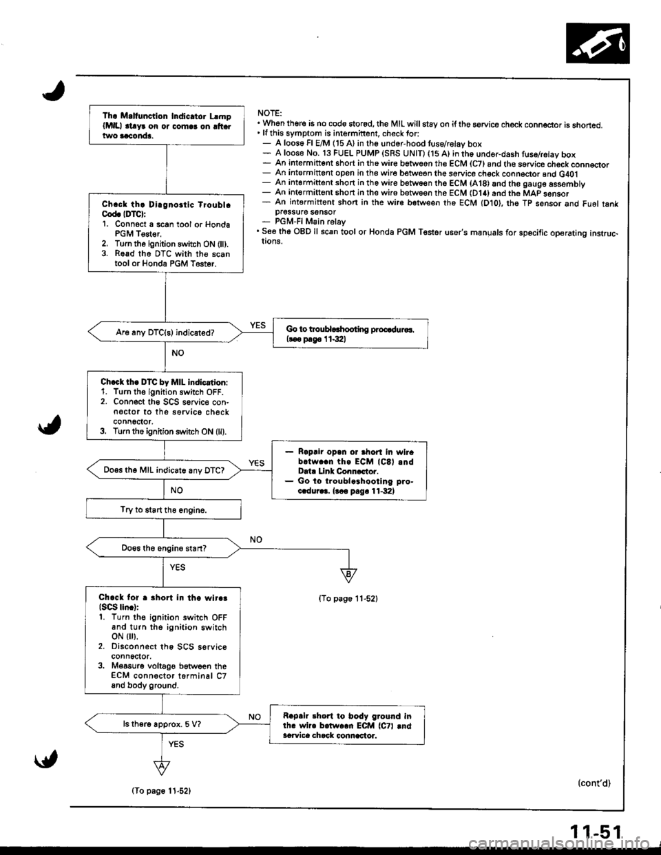
NOTE:. Whon there is no cod6 stored, the MIL willstay on iftho aorvice check conn€ctor is snoned.' lfthis symptom is intermittent. check tor:- A loos6 Fl E/M (15 A) in the undor-hood tuse/relav box- A loose No. 13 FUEL PUMP {SRS UNIT) (15 A) in th6 under-dash fuse/retay box- An intermitt6nt short in the wir€ betwesn the ECM (C7) and th€ sorvice chock conn€qor- An intormittent open in the wire between the sorvice chsck conneclor and G40l- An intermittent short in the wire betwo€n the ECM (A18) and the gaug6 assemDry- An intermittent shon in the wir6 between the ECM (D14) and the MAP sonsor- An intermittent shon in the wire bstween the ECM (Dto), th6 Tp sensor and Fu6l tankpI6SSU16 SOnSOT- PGM-FI Main relay. See th6 OBD ll scan tool or Honda PGM Tester user's manuals for sp6cific operating instruc-!ons.
(To page 11-52)
(cont'd)
Th. M.lfunction Indic.tor LlmplMlll .t!yr on or comlr on ltt .two aaconda.
Ch.ck th! Dirgnoitic tioubl.Cod. IDTC):'1. Connoct a 6can tool or HondaPGM Tester,2. Turn tho ignition switch ON (ll).3. Read tho DTC with the scantool or Honda PGM T6st6r.
Go to trouHorhooting proQduaaa.
koo p.g6 I 1.3:ll
Ch.ct th. DTC by MIL indication:1. Turn th€ ignition switch OFF.2. Connect the SCS seNic€ con-n€ctor to the sorvico checkconnoctor,3. Turn the ignition s1\,itch ON (ll).
Rapair opan or ahort in wirabotw..n thg ECM lCSl .ndData Llnk Conncctor.Go lo troublcrhootlng pro-c.dur.3. {.co pag. 11-32)
Do.s th6 MIL indicate anv DTC?
Try to start tho engine.
Chack lor r 3hort in th. wlr.3lsqg lln.):1. Turn the ignition switch OFFand turn the ignition switchoN { },2. Disconnect th6 SCS serviceconnector,3. M€a6urg voltaOe between theECM connoctor torminal C7and body ground.
Rapah 3hort to body ground inlh. wir. b.lw..n ECM lCTl .ndacwica chack connactor.
ls ther6 approx. 5 V?
\{,
(To page 11-52)
11-51
Page 467 of 1681
![HONDA INTEGRA 1998 4.G Workshop Manual Troubleshooting Procedures
Checking the Diagnostic Trouble Code (DTC)
with an OBD ll Scan Tool or th€ Honda PGM Tester
When the TCM senses an abnormality in the input or output systems, the lD,] ind HONDA INTEGRA 1998 4.G Workshop Manual Troubleshooting Procedures
Checking the Diagnostic Trouble Code (DTC)
with an OBD ll Scan Tool or th€ Honda PGM Tester
When the TCM senses an abnormality in the input or output systems, the lD,] ind](/img/13/6069/w960_6069-466.png)
Troubleshooting Procedures
Checking the Diagnostic Trouble Code (DTC)
with an OBD ll Scan Tool or th€ Honda PGM Tester
When the TCM senses an abnormality in the input or output systems, the lD,] indicator light in the gauge assembly will
blink. When the 16p Data Link Connector (DLC) (located under the dash on the passenger side) is connected to the OBD ll
Scan Tool or Honda PGM Taster as shown, the scan tool or tester will indicate the Diagnostic Trouble Code (DTC) when
the ignition switch is turned ON {ll}.
When the !r indicator light has been reported on, connect the OBD ll Scan Tool confirming to SAE J1978 or Honda PGM
Tester to the DLC (16P) behind the ashtray. Turn the ignition switch ON (ll) and observe the DTC on the screen ofthe OBD
ll Scan Tool or Honda PGM Tester. After determining the DTC, refer to the electrical system Symptom-to-Component
Chart on pages 14-54 and 14-55.
NOTE: SeetheOBDll ScanTool orHonda PGM Tester user's manual for specific instructions.
OBD-IlSCAN TOOL orHONDA PGM TESTER
Some PGM-Fl problems will also make the lol indicator light come on. After repairing the PGM-Fl system. disconnect the
BACK Up fuse (7.5 A) in the under-hood fuse/relay box for more than 10 seconds to reset the TCM memory, then recheck.
NOTE: Disconnecting the BACK UP fuse also cancels the radio anti-theft code, preset stations and the clock setting. Get
the customer's code number, and make note of the radio presets before removing the fuse so you can reset them
uJ trr
ulu
ai
14-50L
DATA LINK CONNECTOR (16P)
I
il
lt
rJq
Page 470 of 1681
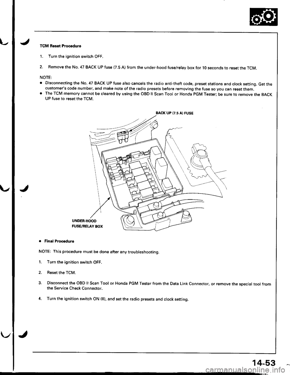
TCM Reset Procodure
1. Turn the ignition switch OFF.
2. Remove the No. 47 BACK UP fuse {7.8 A) from the under-hood fuse/relay box for lO seconds to reset the TCM.
NOTE:
. Disconnecting the No, 47 BACK UP fuse also cancels the radio anti-theft code, preset stations and clock setting, Get thecustomer's code number, and make note of the rsdio presets before removing the fuse so you can reset them.o The TCM memory cannot be cleared by using the OBD ll Scan Tool or Honda pGM Tester; be sure to remove the BACKUP fuse to reset the TCM.
BACK UP (7.5 A) FUSE
J
UNDER.HOOD
FUSE/RELAY BOX
. Final Procodurs
NOTE: This procedure must be done after any trou bleshooting.
1. Turn the ignition switch OFF.
2. Reset the TCM.
3. Disconnect the OBD ll Scan Tool or Honda PGM Tester from the Data Link Connector, or remove the sDecial tool fromthe Service Check Connector.
4. Turn the ignition switch ON (ll), and set the radio presets and clock setting.
14-53
Page 472 of 1681
u.drrf,,
J
J
J
14-55
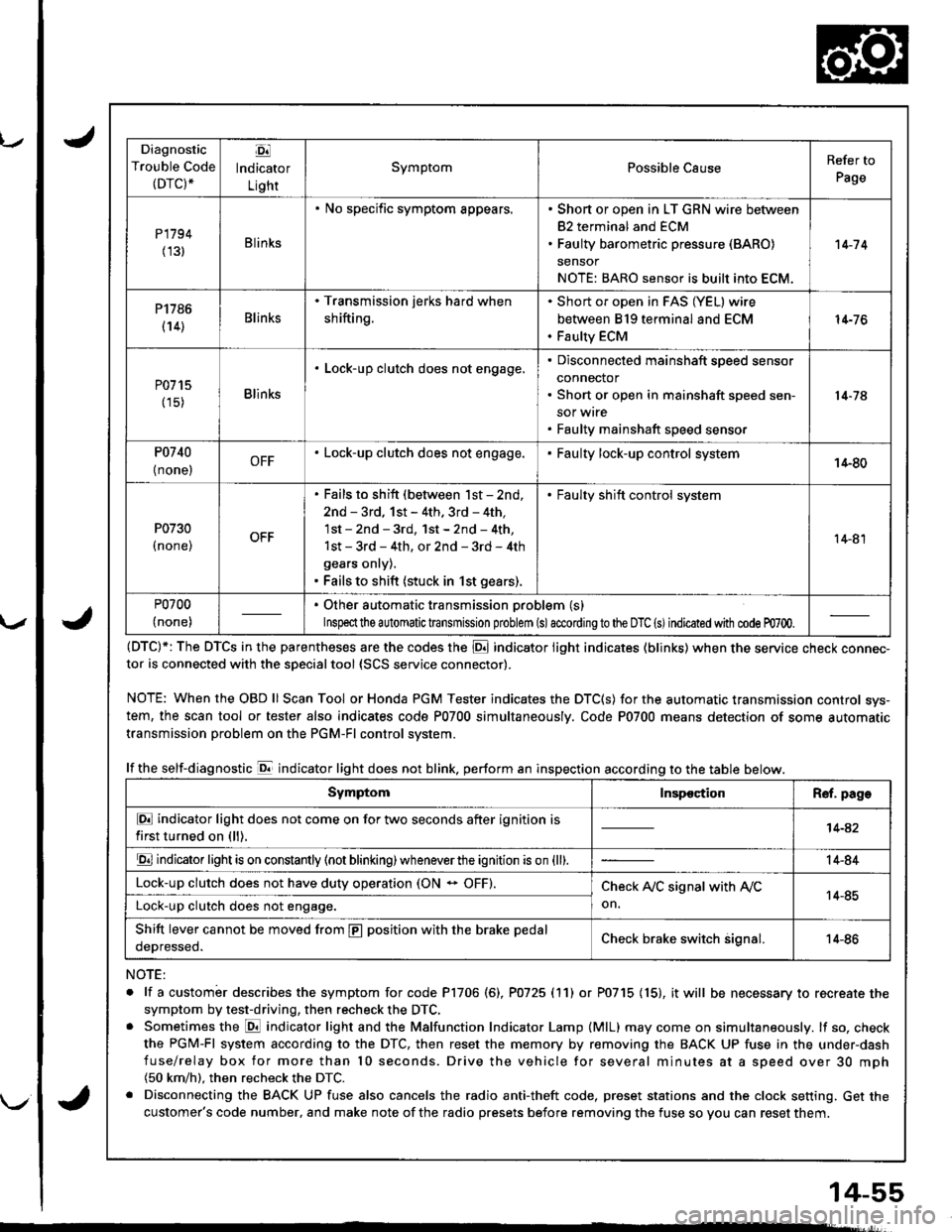
Diagnostic
Trouble Code(DTC).
Ej
lndicator
Light
SymptomPossible CauseRefer to
Page
P1794
(131Blinks
. No specific symptom appears.. Short or open in LT GRN wire between
82 terminal and ECM. Faulty barometric pressure (BARO)
sensor
NOTE: BARO sensor is built into ECM.
't 4-7 4
P1786
(14)Blinks
. Transmission jerks hard when
shifting.
Short or open in FAS (YEL) wire
between 819 terminal and ECM
Faulty ECM
14-76
P0715
(15)Blinks
. Lock-up clutch does not engage,Disconnected mainshaft speed sensor
connector
Short or open in mainshaft speed sen-
sor wrre
Faulty mainshaft speed senso.
14-74
P0740
{ none,OFF. Lock-up clutch does not engage.Faulty lock-up control system14-80
P0730
I none,
. Fails to shift (between lst - 2nd,
2nd - 3rd, 1st - 4th. 3rd - 4th,
1st - 2nd - 3rd, 1st - 2nd - 4th,
1st - 3rd - 4th, or 2nd - 3rd - 4th
gears onry).. Fails to shift (stuck in 1st gears).
. Faulty shift control system
14-81
P0700
(none)
. Other automatic transmission problem (s)
Inspeclthe a utomatic transmission problem (s)accordingto the DTC (s)indicated with code m700.
(DTC)*: The DTCS in the parentheses are the codes the E indicator light indicates (blinks) when the service cnecK connec-tor is connected with the sDecialtool {SCS service connector).
NOTE: WhentheOBDll Scan Tool orHonda PGM Tester indicates the DTC(S) for the automatic transmission control sys-
tem, the scan tool or tester also indicates code P0700 simultaneously. Code P0700 means detection of some automatic
transmission problem on the PGM-Fl control system.
lf the self-diagnostic E indicator light does not blink. perform an inspection according to the table below.
NOTE:
. lf a custombr describes the symptom for code P1706 (6), P0725 (11) or P0715 (15), it will be necessary to recreate the
symptom by test-driving, then recheck the DTC,. Sometimes the E indicator light and the Malfunction Indicator Lamp (MlL) may come on simultaneously. lf so, check
the PGM-Fl system according to the DTC, then reset the memory by removing the BACK UP fuse in the under-dash
fuse/relay box for more than l0 seconds. Drive the vehicle for several minutes at a speed over 30 mph(50 km/h). then recheck the DTC.
. Disconnecting the BACK UP fuse also cancels the radio anti-theft code, preset stations and the clock setting. Get the
customer's code number, and make note of the radio presets before removing the fuse so you can reset them.
SymptomInspectionR€f. page
E indicator light does not come on for two seconds after ignition is
first turned on (ll).14-42
E indicator light is on constantly (not blinking) wheneverthe ignition is on {ll).14-84
Lock-up clutch does not have duty operation (ON - OFF).Check A,/C signal with Ay'C
on.14-85Lock-up clutch does not engage.
Shift lever cannot be moved from E position with the brake pedal
oeDresseo.Check brake switch signal.14-86
Page 473 of 1681
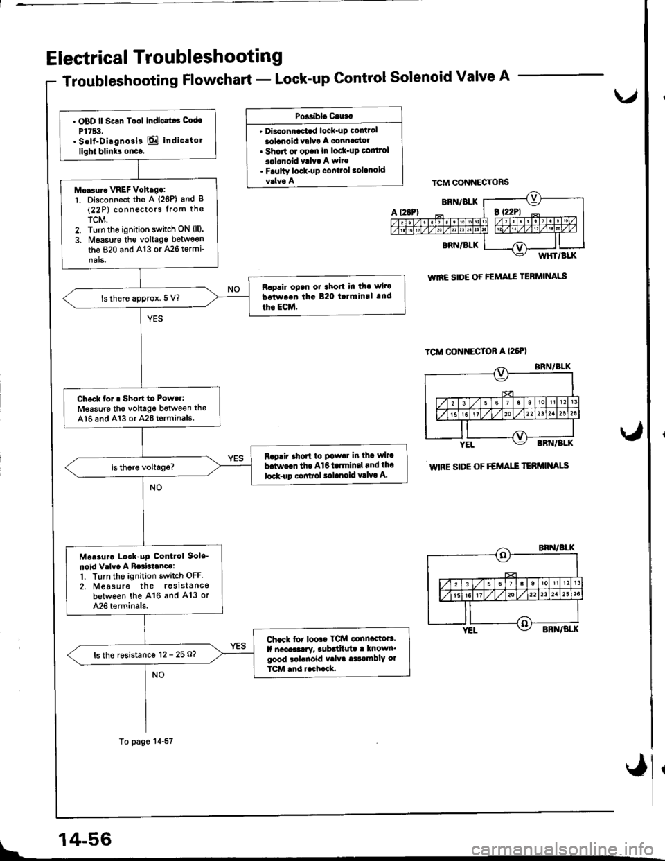
Electrical Troubleshooting
Troubleshooting Flowchart - Lock-up Control Solenoid Valve A
Po+tible Cauta
' Diaconnac'tad lock-up control
lolanoid valva A connac'toa. Shon or opan in lod(-up co|ltrol
3olonoid valva A wire. Faulty lock-up cont?ol lolanoid
TCM CONNECTORS
WIRE SIOE OF FEMAI."E TERMINALS
WIRE SIDE OF FEMA.E TEBMINAIS
L/
. OBD ll Scrn Tool indic|t.3 Cod.
P17!i:t.. Self-Dirgnoii! E indic.torlight blinkr onco.
M.Nur. VREF Voh.go:'t. Disconnect the A (26P) and B(22 P) conn€ctors lrom th€
TCM.2. Turn tho ignition switch ON (ll).
3. Nleasure tho voltage betwson
the 820 and A13 or A26 tormi-nals.
Raplir opan or 3hort in tha wi.a
b.twa.n th. B20 t.lmin!l .nd
th€ EcM.lsthere approx. 5 V?
Check tor a Short to Powa.i
Measure tho voltag€ botwoen the
A16 and A13 or A26 terminals.
Rap!fu ahorl to Pow.t in tha wlra
b!tw..n th. A16 t rmln.l rnd tho
lock-up c!filtol lolaooid valvo A.
Moaaurc Lock-uP Contlol Sole-
noid Vrlvo A Be3bianco:1. Ttrrn the ignition switch OFF.
2. Measure the rssistancebetween the A16 and A13 or
A26 terminals.
Chack tor loolc TCM conncctora.lf naca!3!ry, rub3tftuta a known'good rolcnold v.lva a$amblY ol
TCM .nd r.ch.ck.
ls the rosistanco 12 - 25 O?
To page 14-57
\
14-56
Page 475 of 1681
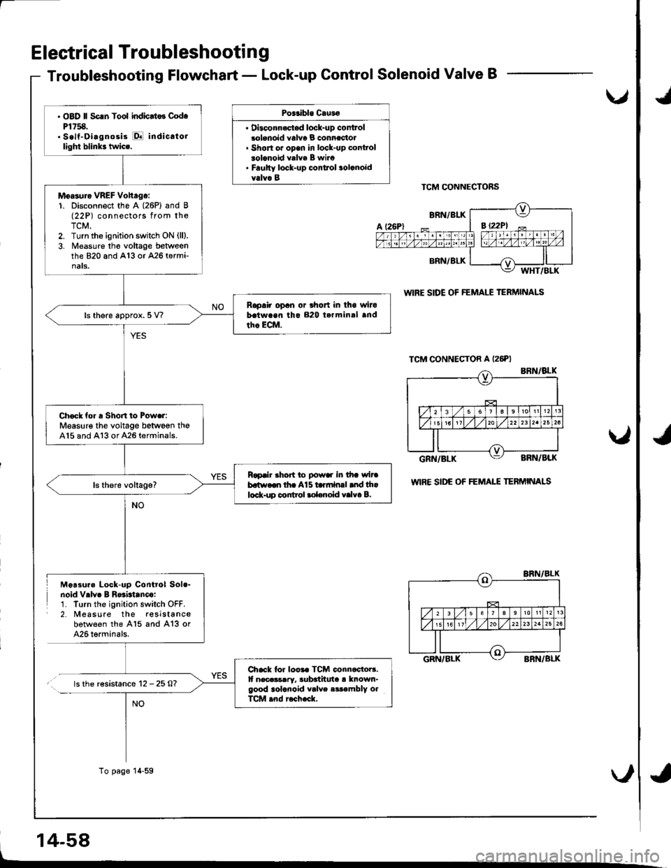
Electrical Troubleshooti n g
Troubleshooting Flowchart - Lock-up Control Solenoid Valve B
Poitibl. Cau3o
. Dbconn.stsd lock-up controlsolenoid valv6 B connectol. Short or open in lock-up cont.ol3olonoid valva B wiro. Faulty lock-up conttol solcnoidvalva BTCM CONNECTORS
WIRE SIDE OF FEMALE TERMINALS
wlRE SIDE OF FEMAIE TERMINALS
Moa3ure Lock-up Control Sol.-noid Vrlv. B R$btanco:1. Turn the ignition switch OFF.2. Measure the reslstancebotween the A15 and A13 or426 terminals.
.. ls the r€sistance 12 -25A?
14-58
u,
NO
. OBD ll Scrn Tool indicrt.3 Cod.P1758.. Self-Oiagnosis E indicato.light blink3 twics.
Moasuro VREF Vohago:1. Disconnect the A (26P) and B(22P) connectors from theTCM.2. Turn the ignition switch ON (ll).
3. Measure tho voltage betweenthe 820 and A13 or 426 termi-nats.
Rapair opan or lhort in iho wirobatwaan tho 820 terminal andth. ECM.ls there approx. 5 V?
Check for a Shon to Powar:Measure the voltage between th€A15 and A13 or A26 terminals.
Rapair .hort to powar in tha wircbatr.,aon tha A15 ta.mlnal and thalock.up control rol.noid valva B.
Chack for loo.. TCM connactoB.It necassrry, 3ub3thuta ! known-good 3olcnoid valve .ir€mbly olTCM .nd r6ch.ck.
To page 14-59
*d
*,