cruise control HONDA INTEGRA 1998 4.G Workshop Manual
[x] Cancel search | Manufacturer: HONDA, Model Year: 1998, Model line: INTEGRA, Model: HONDA INTEGRA 1998 4.GPages: 1681, PDF Size: 54.22 MB
Page 36 of 1681
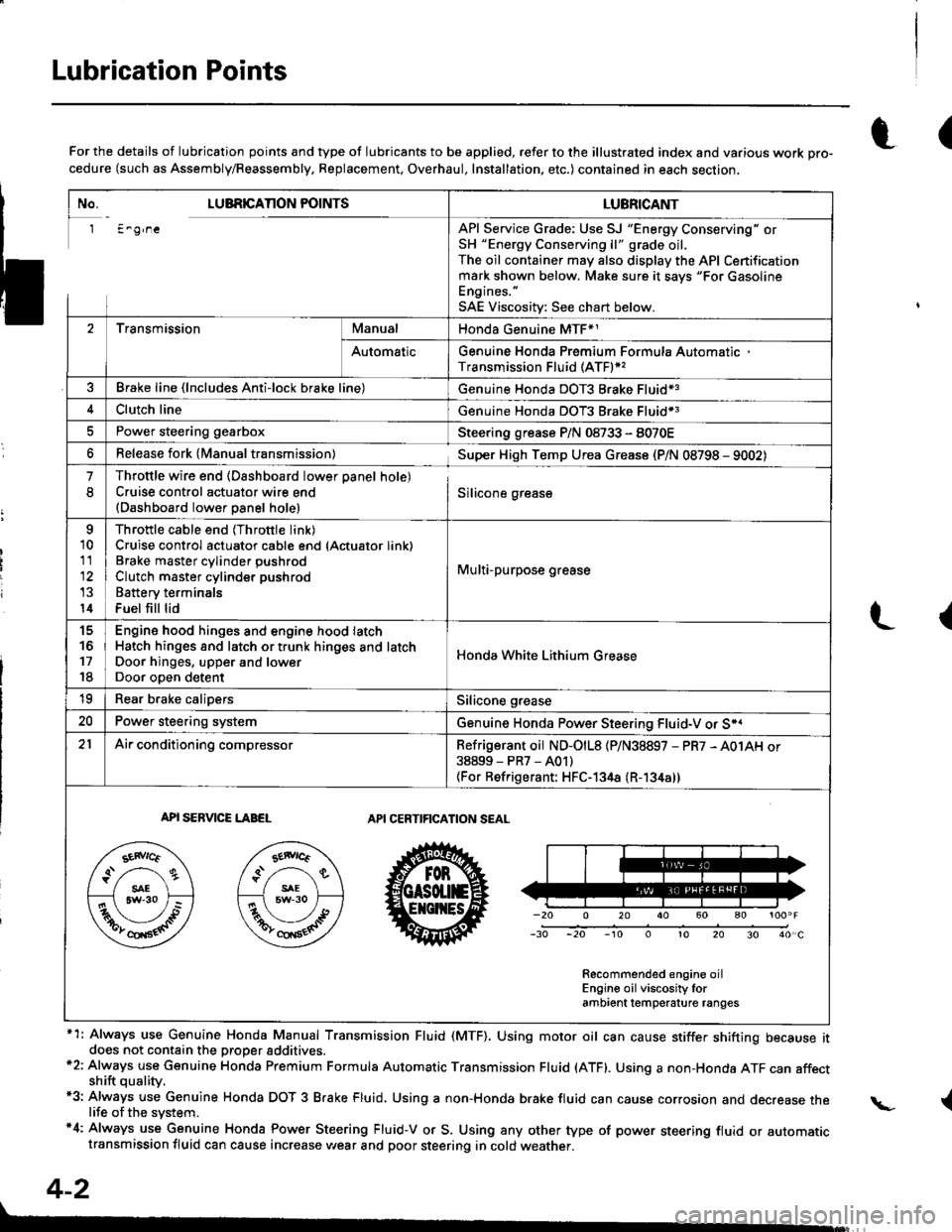
Lubrication Points
No. LUBRICAnON POINTSLUBRICANT
1 E^g,neAPI Service Grade: Use SJ "Energy Conserving" orSH "Energy Conserving ll" grade oil,The oil container may also display the API Certificationmark shown below. Make sure it savs "For GasolineEngines. "
SAE Viscositv: See chart below.
2TransmissionManualHonda Genuine MTF*1
AutomaticGenuine Honda Premium Formula AutomaticTransmission Fluid (ATF)*,
Brake line (lncludes Anti-lock brake line)Genuine Honda DOT3 Brake Fluid13
Clutch lineGenuine Honda DOT3 Brake Fluid*3
Power steering gearboxSteering grease P/N 08733 - 8070E
Release fork lManual transmission)Sup€r High Temp Urea Grease (P/N 08798 - 9002)
1
8
Throttle wire end (Dashboard lower oanel hole)Cruise control actuator wire end(Dashboard lower Danel hole)Silicone grease
o
10
11
14
Throttle cable end (Throttle link)Cruise control actuator cable end (Actuator link)Brake master cvlinder oushrodClutch master cylinder pushrod
Battery terminals
Fuel fill lid
Multi-purpose grease
to
17
18
Engin6 hood hinges and engine hood latchHatch hinges 8od latch or trunk hinges and latchDoor hjnges, upper and lowerDoor ooen detent
Honda White Lithium Grease
19Rear b.ake calipersSilicone grease
20Power steering systemGenuine Honda Power Steering Fluid-V or S*.
21Ai|' conditioning compressorRefrigerant oii ND-O|L8 {P/N38897 - PR7 - A01AH or38899-PR7-A01)(For Refrigerant: HFC-134a (R- 134a))
API SERVICE LABELAPI CERTIFICATION SEAL
Recommended engine oilEngin€ oil viscosity lorambrent lemperature ranges
r(For the details of lubrication points and type of lubricants to be applied, refer to the illustrated index and various work Dro-cedure (such as Assembly/Reassembly, Replacement, Overhaul, Installation. etc.) contained in each section,
*1: Always use Genuine Honda Manual Transmission Fluid (MTF). Using motor oil can cause stiffer shifting because itdoes not contain the proper addtuves.*2: Always use Genuine Honda Premium Formula Automatic Transmission Fluid (ATF). Using a non-Honda ATF can affectshift quality.*3: Always use Genuine Honda DOT 3 B.ake Fluid, Using a non-Honda brake fluid can cause corrosion and decrease thelife of the system.'4: Always use Genuine Honda Power Steering Fluid-V or S. Using any other type of power steering fluid or automatictransmission fluid can cause increase v,/ear and poor steering in cold weather.
L(
{
4-2
Page 48 of 1681
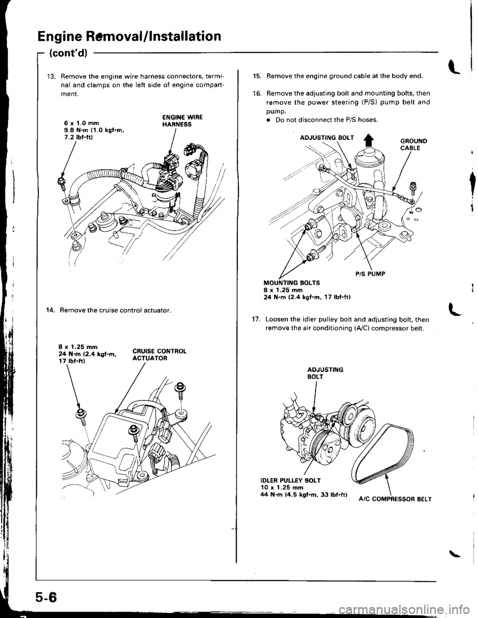
Engine Ramoval/lnstallation
(cont'dl
13. Remove the engine wire harness connectors, termi-
nal and clamps on the left side ot engine compan-
menr,
6 x 1.0 mm9.8 N.m 11.0 kgl.m,7.2 tbt.ttl
14. Remove the cruise control actuator.
I x 1.25 mm24 N.m 12.4 kgt.m,17 tbt.ft)
5-6
A/C COMPRESSOR EELT
\
l.15.
to.
Remove the engine ground cable at the body end.
Remove the adjusting bolt and mounting bolts, then
remove the power steering (P/S) pump belt and
pump.
. Do not disconnect the P/S hoses.
MOUNTING BOLTSI x 1.25 mm24 N.m 12.4 kgt'm, 17 lbl.ft)
Loosen the idler pulley bolt and adjusting bolt, then
remove the air conditioning (Ay'C) compressor belt.
IDLER PULLEY BOLT10 x 1.25 mm/14 N'm 14.5 kgf.m, 33 lbt'frl
I
I
't7.
Page 290 of 1681
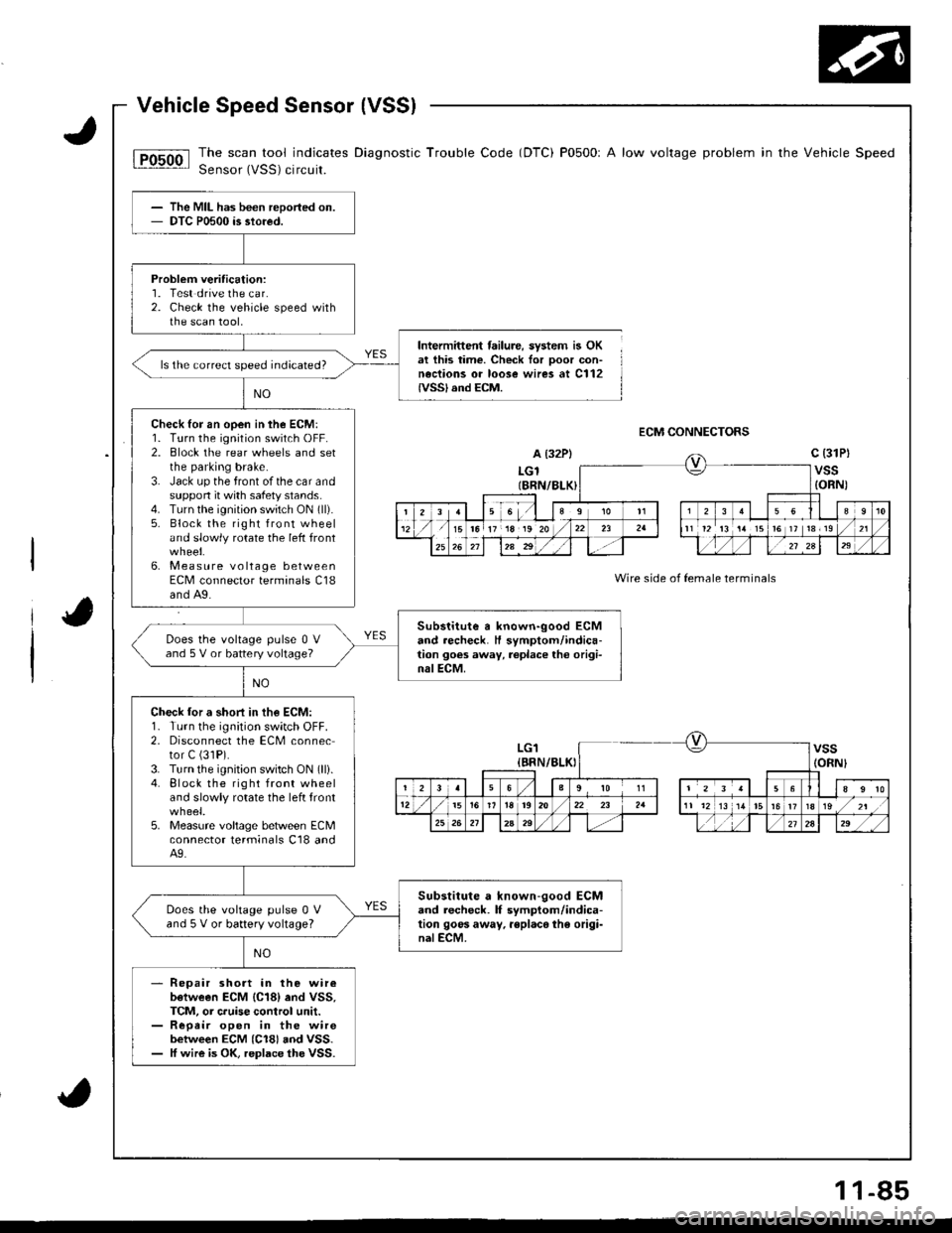
The scan tool indicates Diagnostic Trouble Code (DTC) P0500r A low voltage problem in the Vehicle Speed
Sensor (VSS) circuit.
Intermittent failure, system is OKat this time. Check for ooor con-neciions or loose wires at C112IVSSI and ECM.
ECM CONNECTORS
A (32P)
LGlIBRN/8LK)
c (31Pt
vss{ORN)
Wire side of female terminals
The MIL has been reported on.DTC P0500 is stored.
Probleft veritication:1. Test drive the car.2. Check the vehicle speed withthe scan tool,
ls the correct speed indicated?
Check lor an open in the ECM:1. Turn the ignition switch OFF.2. Block the rear wheels and setthe parking brake.3. Jack up the front of the car andsuppon it with safety stands.4. Turn the ignition switch ON (ll).
5. Block the right front wheeland slowly rotate the left front
6. Measure voltage betweenECM connector terminals C18and A9.
Substitute a known-good ECMand recheck. H symptom/indica-tion goes away, replace tho origi-nalECM.
Does the voltage pulse 0 Vand 5 V or battery voltage?
Check lor a shori in th€ ECM:1. Turn the ignition switch OFF.2. Disconnect the ECM connector C (31P).
3. Turn the ignition switch ON (lli.4. Block the right front wheeland slowly rotate the left front
5. Measure voltage between ECMconnector lerminals C18 andA9.
Substitute a known-good ECMand lecheck. lf symptom/indica-tion goos away. rsplaco the origi-nalECM.
Does the vohage pulse 0 Vand 5 V or battery voltage?
Repair short in the wireb€tween ECM {C18} end VSS,TCM, or cruise control unit.Repeir open in the wirebetween ECM (C18) aod VSS.ff wire is OK, replace the VSS.
ra 17 18 19 20t6 ]t 13r19
LG1{BRN/BLKIvss(ORNI
23563910 1156
12i5r92022 23 2a11 1213 1/tr6ts/zt
25262Aa9,/2724," ,/ ,,:
1 1-85
Page 673 of 1681
Steering Wheel
Removal
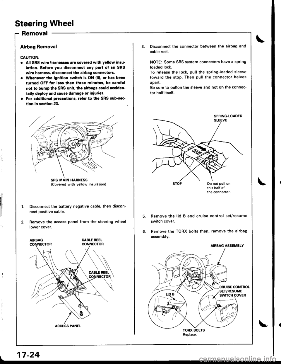
Airbag Removal
'CAUTION:
. All SRS wiro harne33e3 ar€ coverad with yellow insu.
lation. Beforo you di3connect Eny part of En SRS
wiro harn6ss, disconnsct the airbag conncctors.
. Whenaver ths ignition switch is ON {ll}, or ha3 b.cn
turned OFF lor l.3s than thrcc minuto3, be cErs{ul
not to bump th6 SRS unh; the airbags could rcciden-
tally deploy and cause damsgo or iniurias'
. Fo. additional preclution3, rofer to tho SRS sub-soc'
tion in 36ction 23,
Disconnect the battery negative cable, then discon-
nect Dositive cable.
Remove the access panel from the steering wheel
lower cover.
CABLE REEL
L
SRS MAIN HARNESS
17-24
Disconnect the connector between the airbag and
cable reel.
NOTE: Some SRS system connectors have a spring
loaded lock.
To release the lock, pull the spring-loaded sleeve
toward the stop. Then pull the connector halves
apart.
Be sure to pullon the sleeve and not on the connec-
tor half itself.
Remove the lid B and cruise control set/resume
switch cover.
Bemove the TORX bolts then, remove the airbag
assembly.
SPRING.LOADED
AIRBAG ASSEMBLY
Page 674 of 1681
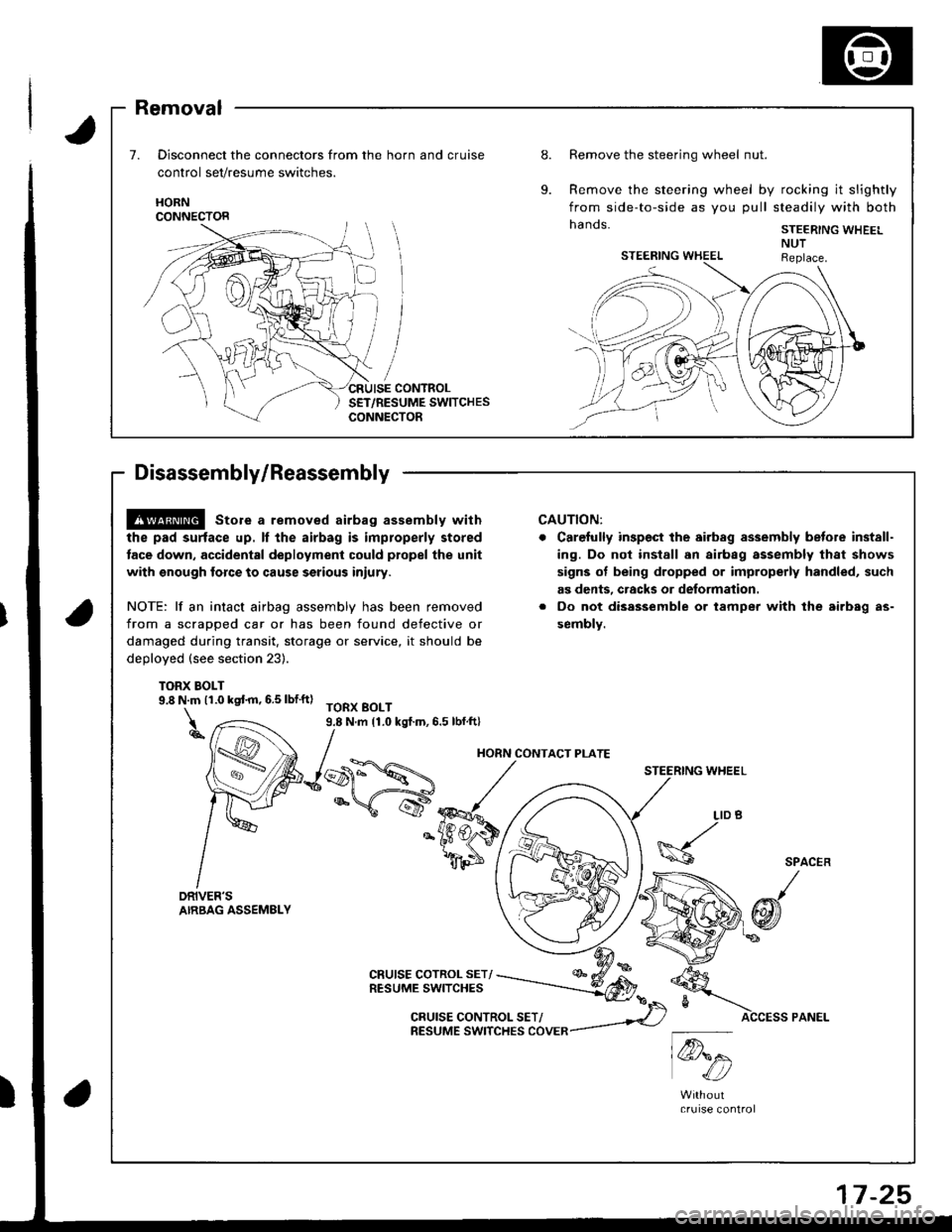
Removal
Disconnect the connectors from the horn and cruise
control set/resume switches.
Remove the steering wheel nut.
Remove the steering wheel by rocking it slightly
from side-to-side as you pull steadily with both
hands. STEER|NG WHEEL
HORNCONNECTOR
7 -25
@ store a removed airbag assembly with
the pad surtace up. ll the airbag is improperly stored
tace down. accidental deployment could propel the unit
with snough force to cause serious iniury.
NOTE: lf an intact airbag assembly has been removed
from a scrapped car or has been found defective or
damaged during transit, storage or service, it should be
deDloyed (see section 23).
TORX BOLT9.8 N.m (1.0 kqt m, 6.5 lbf'ft)TORX BOLT9.8 N.m 11.0 kgf.m,6.5 lbf.ft)
CRUISE COTROL SET/RESUME SWITCHES
CAUTION:
Carefully inspect the airbsg assembly betore inst8ll-
ing. Do nol install 8n airbag assembly that shows
signs ot being dropped or improperly handled, such
as dents, cracks or deformation.
Oo not disassemble or tampel with the airb8g as-
sembly.
STEERING WHEEL
\@.
LID
h6
w1c4:,/bA
4t
SPACER
@f
CRUISE CONTROL SET/RESUME SWITCHES COVER
HORN CONTACT PLATE
Page 675 of 1681
Steering Wheel
lnstallation
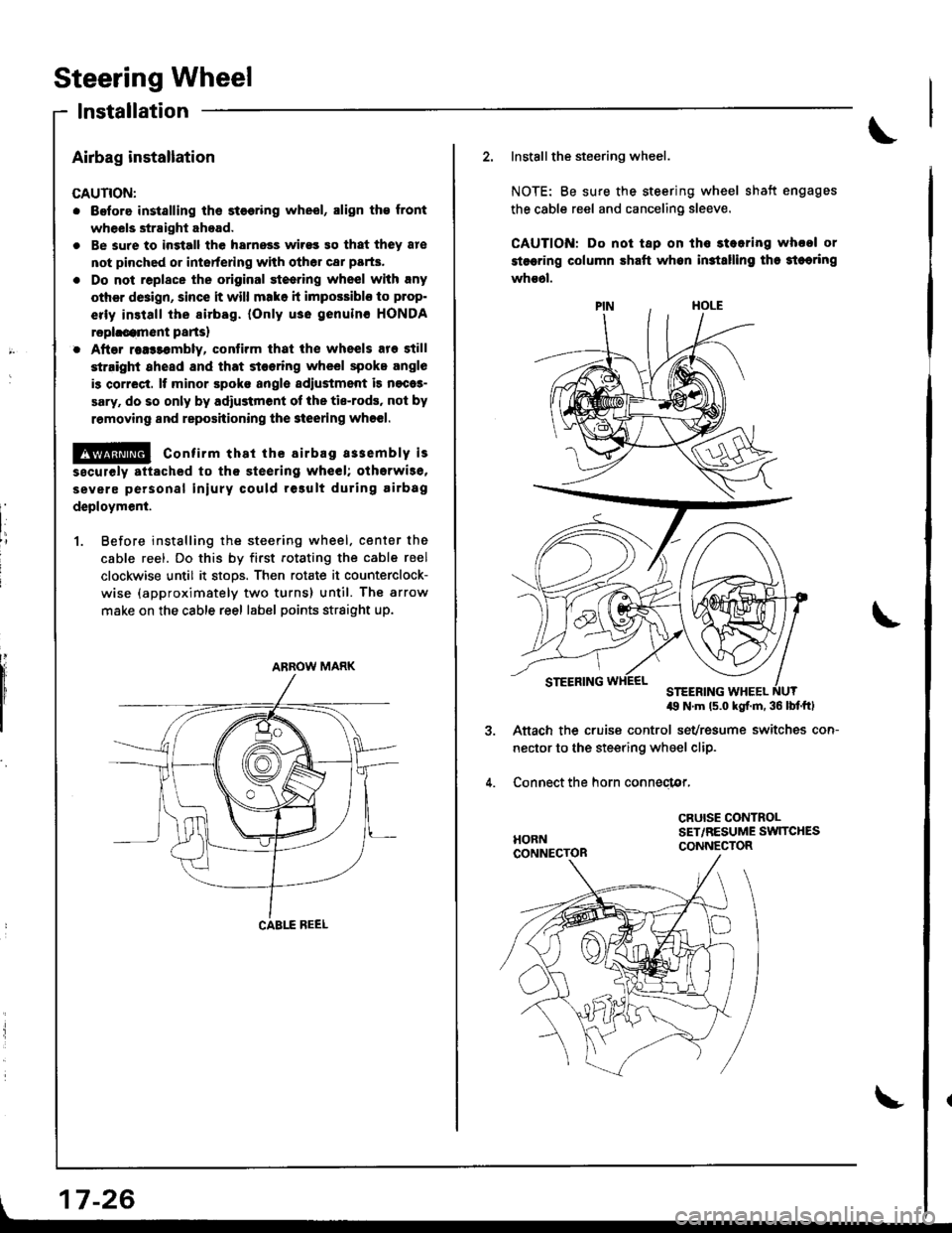
Airbag installation
CAUTION:
. Before installing ths st€€ring wheel, align th€ front
wheels straight ahead.
. Be sure to ingtall the harnoss wirss 90 that they 8re
not pinched or intorfering with other car parts.
. Do not replace the original st€ering wheel with rny
other d8ign, since it will mako h impossiblo to p.op-
erly install the sirbag. {Only use genuinc HONDA
rephcamont parts)
. After rea$embly, contirm that ih€ wheels are still
st.ight 8head and that stooring wheel spoke angle
is correct. It minor spoko aogle sdiustment is n€cas-
sary. do so only by adiustment ol the tis-rods, not by
removing and reposhioning the 3teering who€|.
!@ confirm thst the airbag a33embly is
sscurely attached to th€ steering wheel; otherwi3e,
severe personal iniury could result during airbag
deploymenl.
1. Before instslling the steering wheel. center the
cable reel. Do this by first rotating the cable reel
clockwise until it stoos. Then rotate it counterclock-
wise (approximately two turns) until. The arrow
make on the cable reel label points straight up.
ARROW MARK
| 17-26
\
2. Installthe steering wheel.
NOTE: Be sure the steering wheel shatt engages
the cable reel and canceling sleeve.
CAUTION: Do not tap on ths stearing whool or
stsering column shaft whon in3tslling tha 3teoring
whs6l.
49 N'm ls.o kgf.m. 36 lbf'ftl
Aftach the cruise control sevresume switches con-
nector to the steering wheel clip.
Connect the horn conneclor,
CRUISE CONTROLSET,/RESUME SW]TCHESCONNECTOR
Page 676 of 1681
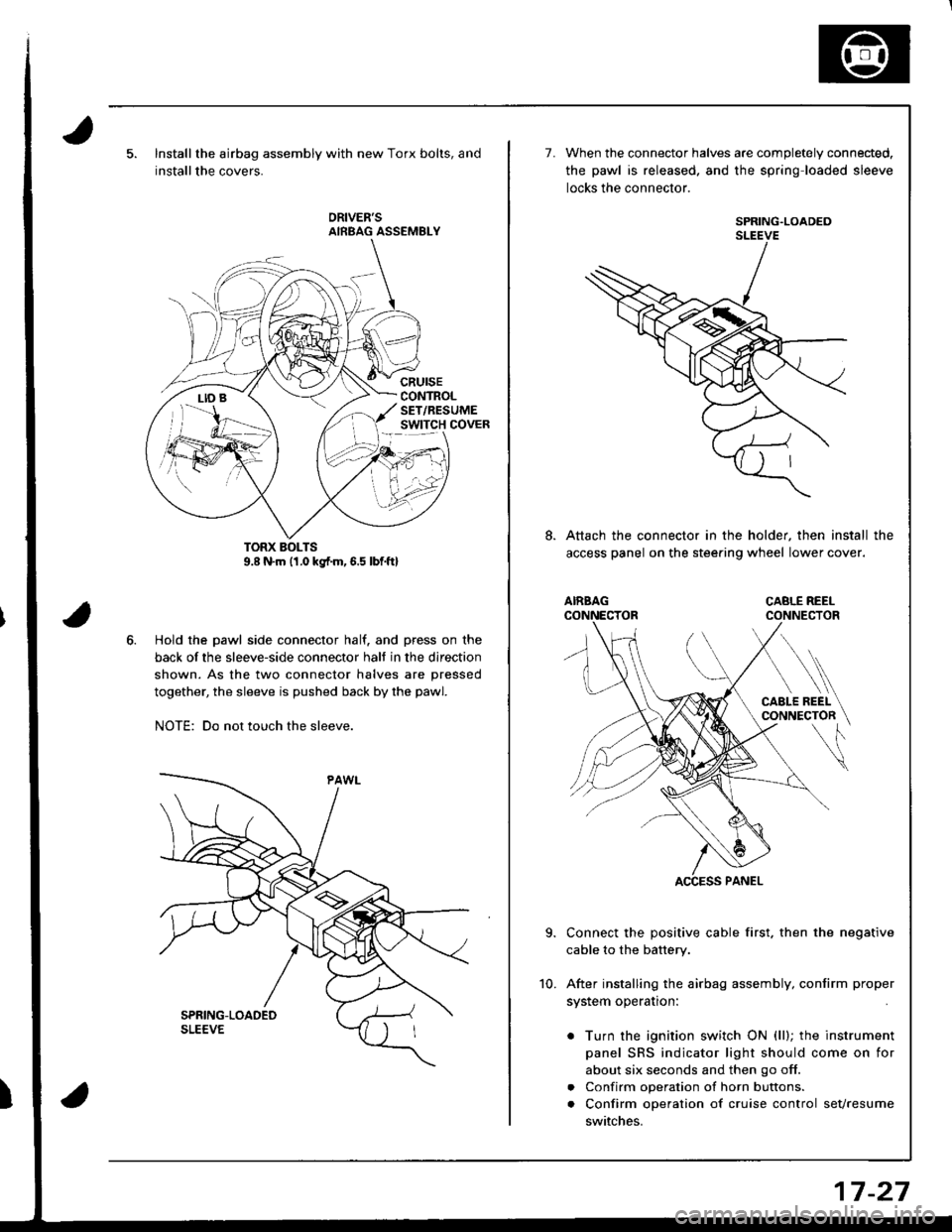
Installthe airbag assembly with new Torx bolts, and
installthe covers.
cRursECONTROLSET/RESUMEswtTcH covER
Hold the pawl side connector half. and press on the
back of the sleeve-side connector halt in the direction
shown. As the two connector halves are pressed
together, the sleeve is pushed back by the pawl.
NOTE: Do not touch the sleeve.
7.When the connector halves are completely connected.
the pawl is released. and the spring loaded sleeve
locks the connector.
SPRING.LOADEDSLEEVE
Attach the connector in the holder, then install the
access panel on the stee.ing wheel lower cover.
Connect the positive cable first. then the negative
cable to the battery.
After installing the airbag assembly, confirm proper
system operation:
. Turn the ignition switch ON (ll); the instrument
panel SRS indicator light should come on for
about six seconds and then go off.
. Confirm operation of horn buttons.
. Confirm operation of cruise control sevresume
switches.
10.
17-27
Page 682 of 1681
9.
1.
8.
11.
10.
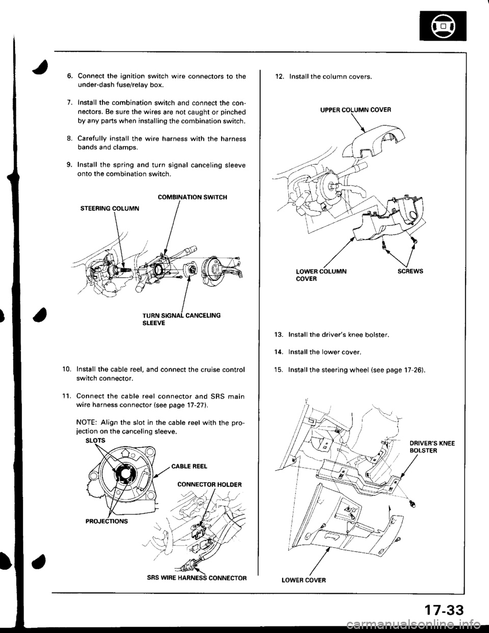
Connect the ignition switch wire connectors to the
under-dash fuse/relay box.
Install the combination switch and connect the con,
nectors. Be sure the wires are not caught or pinched
by any parts when installing the combination switch.
Carefully install the wire harness with the harness
bands and clamps.
Install the spring and turn signal canceling sleeve
onto the combination switch.
Install the cable reel, and connect the cruise control
switch connector.
Connect the cable reel connector and SRS main
wire harness connector (see page '17-27).
NOTE: Align the slot in the cable reel with the pro-jection on the canceling sleeve.
CABLE REEL
CONNECTOR HOLDER
COMBINATION SWITCH
SLEEVE
SRS WIRE
17-33
12. Installthe column covers.
UPPER COLUMN COVER
LOWER COLUMNCOVERscREws
13.
14.
Install the driver's knee bolster.
lnstall the lower cover.
Install the steering wheel (see page 17 26).
LOWEF COVER
Page 1058 of 1681
J
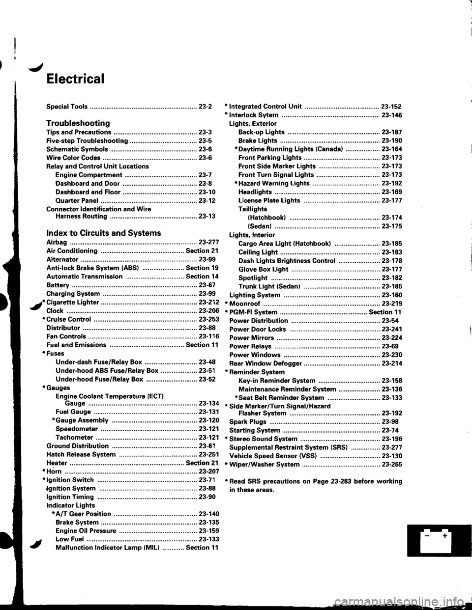
Electrical
Speciaf Toofs ..........................23-2
Troubleshooting
Tips 8nd Precautions .......................,..,.,.,.,.,......,..., 23-3
Five-step Troubleshooting ............,......,.,.,...,..,....., 23-5
Schsmatic Svmbols ...............23-6
Wire Color Code3 .. ................. 23-6
Relay and Control Unit Locations
Engine Compartment ......,.,.................,.,.,.,.,.,,,, 23-7
Dashboard and Door .........,...........,.....,.,....,.,.... 23-8
Dashboard and Floor ......................................... 23-10
Ouarter Pan€f .,,.,...,.,..,...,,,23-12
Connector ldontification and WireHarness Routing ......,.,......23-'13
Index to Circuits and Systems
Airbag
* Integrated Control Unit .....,.,.,.....23-152* Interlock Sytem .,...,.,...........,. 23.146
Lights, Exterior
Eack-up LighB ..................23.187
Brake Ligh$ ......................23-190*Daytime Running Lights (Canada) ................... 23"164
Front Parking Lights .......................................... 23-173
Front Side Marker Lights .................................. 23-173
Front Turn Signal Lights ..................-.......,...,.,. 23-173* Hazard Warning Lights ....................,........,....... 23-192
Headlights.....23-169
23-253 powerDistribution..................... 23-5/r
Air Conditioning.....,....... Soction 21
Alternator ..........,................... 23.99
iCigarette Lighter .........23-212
*Cruise Control
Distributor
'.'.,.'.'.,.'...,,,,.,''.'.,.',.'''.' 23.277
.............................. 23.88
................... 23-90lgnition Timing ......
Indicator Lights
Key-in Reminder System
Maintenance Reminder System*Seat Belt R€mindor System .,...........................* Side Marker/Turn Signal/HazardFlashcr Svstem .................23-192
Spark Plugs ............................23-98
Starting System .....................23-74* Stereo Sound System ...,......,..........,...,......,.,.,.,..,., 23-196
Supplemental Restraint System (SRS) ................ 23-277
Vshicle Speed Sensor (VSS) ................................. 23.130r Wiper/Washer System .........................................., 23-265
*Read SRS precautions on Psge 23-283 before working
in those areas,
23-154
23.136
23"133
Page 1065 of 1681
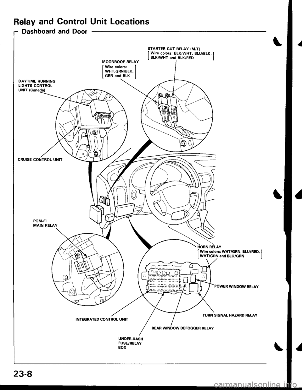
Relay and Control Unit Locations
Dashboard and Door
CRUISE CONTROL UNIT
PGM.FIMAIN RELAY
STARTER CUT RELAY IM/TI
I Wire colors: BLK/WHT, BLUi 8LK, II BLK/WHT and BLK/RED jMOONROOF RELAY
Wire colors:WHT,GBN/BLK,GRN and 8LK
I Wir. cotoF: WHT/GRN, BLU/RED, I
lWHT/GRN and BLU/GRN I
POWER WINDOW BELAY
23-8
INTEGRATED CONTROL UNIT