HONDA INTEGRA 1998 4.G Owner's Manual
INTEGRA 1998 4.G
HONDA
HONDA
https://www.carmanualsonline.info/img/13/6069/w960_6069-0.png
HONDA INTEGRA 1998 4.G Owner's Manual
Page 1215 of 1681
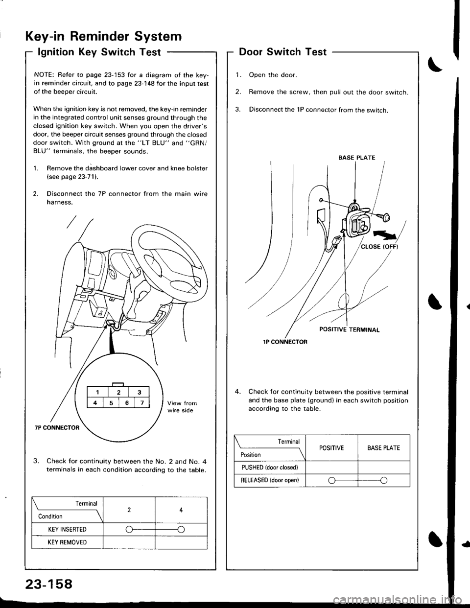
Key-in ReminderSystem
lgnition Key SwitchTest
\f
DoorSwitchTest
1. Open the door.
2. Remove the screw, then pull out the door switch.
3. Disconnect the 1P connector from the switch.
1P CONNECTOR
4. Check for continuity between the positive terminal
and the base plate (ground) in each switch position
accordinq to the table.
BASE PLATE
Terrninal
PositionPOSITIVEBASE PLATE
PUSHED (door closedl
RELEASED (door open)oo
NOTE: Refer to page 23-153 for a diagram of the key-
in reminder circuit, and to page 23-148 for the input test
of the beeper circuit.
When the ignition key is not removed. the key-in reminder
in the integrated control unit senses ground through the
closed ignition key switch. When you open the driver's
door, the beeper circuit senses ground through the closed
door switch. With ground at the "LT BLU" and "GRN/
BLU" terminals, the beeper sounds.
1. Remove the d;shboard lower cover and knee bolster
(see page 23-71).
2. Disconnect the 7P connector from the main wire
narness.
3. Check lor continuity between the No. 2 and No. 4terminals in each condition according to the table.
Terminal
Condition2
KEY INSERTEDo--o
KEY BEMOVED
23-158
Page 1216 of 1681
)
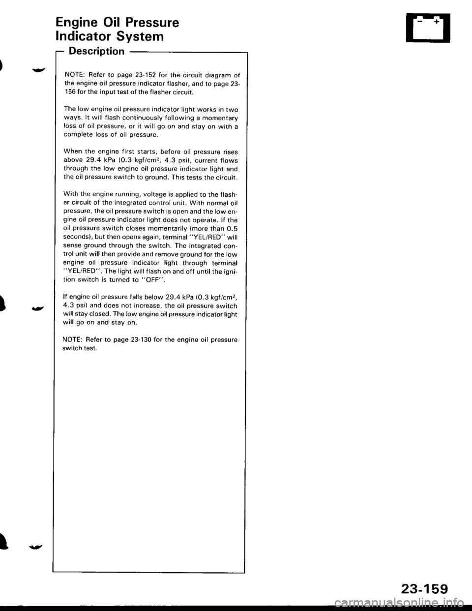
Engine Oil Pressure
Indicator System
Description
NOTE: Refer to page 23-152 for the circuit diagram ofthe engine oil pressure indicator flasher. and to page 23
156 for the input test of the flasher circuit.
The low engine oil pressure indicator light works in twoways. lt will flash continuously following a momentaryloss ol oil pressure, or it will go on and stay on wath a
complete loss of oil pressure.
When the engine first starts, before oil pressure rises
above 29.4 kPa (O.3 kgf/cmr, 4.3 psi), current flows
through the low engine oil pressure indicator light andthe oil pressure switch to ground. This tests the circuit.
With the engine running, voltage is applied to the Ilash-er circuit of the integrated control unit. With normal oilpressure, the oil pressure switch is open and the low en-gine oil pressure indicator light does not operate. lf the
oil pressure switch closes momentarily (more than O.5
seconds). but then opens again, terminal "YEL/RED" will
sense ground through the switch- The integrated con-trol unit will then provide and remove ground tor the low
engine oil pressure indicator light through terminal"YEL/RED". The light will flash on and off untilthe igni
tion switch is turned to "OFF".
lf engine oil pressure talls below 29.4 kPa (O.3 kgf/cmr,
4.3 psi) and does not increase, the oil pressure switchwill stay closed. The low engine oil pressure indicator light
will go on and stay on.
NOTE: Refer to page 23-130 for the engine oil pressure
switch test.
I
23-159
Page 1219 of 1681
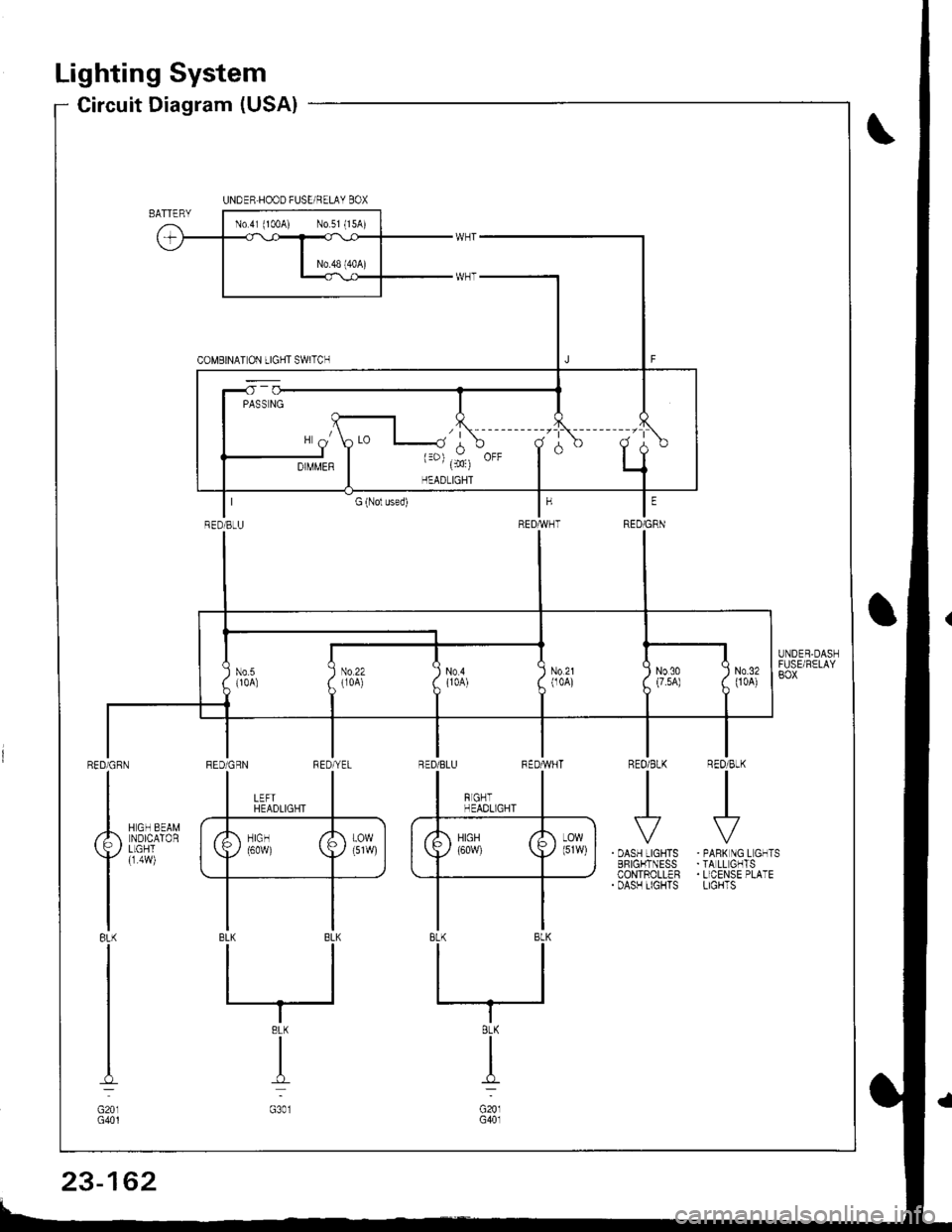
Lighting System
Circuit Diagram (USA)
R€O/BtK
I
REO/BLKIII
I
. OASH LIGHTSBFIGI.ITNESSCONTROLLER. DASH TIGHTS
RED/CRN
I
Ailsurax
Yller,l
IBL(
I
I
I-l
G201G401
. PANK NG L GNTS.TA LL GHTS. LICENSE PLATELIGHTS
UNDER.HOOD FUSE/RELAY BOX
RED]BtU
N0.21(104)No.5{10A)
III No22 I No4( lroA) ( {1oA)
IT
INo30 :(7.5A) (
I
N0.3200A)
8LK
I
G20lG40l
23-162
Page 1220 of 1681
UNDER.HOOD FUSE/RELAY BOX
No 41 {100A) N0.42 (40A)
,/ |\
\--, ({c)
HEADLIGHT
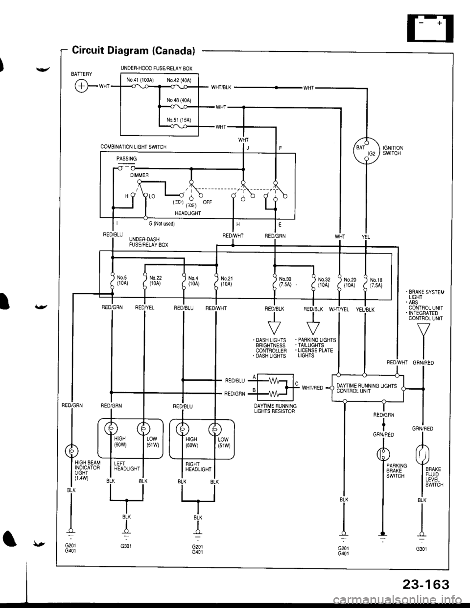
Circuit Diagram (Canada)
BATTEFY
@-**
I I :i,ff'*''"
I CoNTFOL UN|TI . INTEGBATED
l-v^"
tl
tlREDAVHT GRN/RED
GRN/FED
L
lt ))
Yro^,
I iivP,
I
swrrcH
BLK
I
I-l
G301
RED/GFN
tGRN/RED
A
Y*r*ro
I
3Ai{5"
I
I
I
DAYTIME BUNNINGL]GHIS RESISTOR
UNDER.DASHFUSE/FELAY BOX
) No.21
i
uoo') N0.20{JOA))'
) N0.18(7.5A))'
II
lrrt,
llrffi ltlrr
INo.3o Q
(7.sA) . (
I
N0.32(104)
RED GqN RED YE- RED BL- REDTVHT FED/BLK REO/8LK WHT/YEL YEUBLK
| + +ll
I
i*n[i+'i .ffi$liilTl
II ri---J- i---F BEDE-U +1 4- l^ |
l,,oo,* *qff
.'""0
{36['45,1'il]''
23-163
Page 1235 of 1681
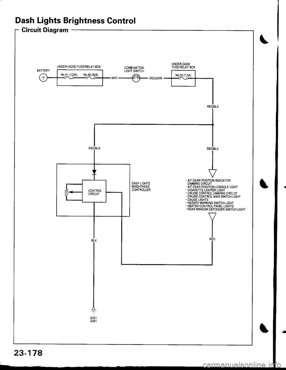
Dash Lights Brightness Control
Circuit Diagram
UNDER-HOOO FUSgRELAY 8OXUNDEN.DASHFUSE/RELAYEOXtX"f -.------^-;^*;;ilLrcrTswrc.
ffiwHT-lf-FEDGaN
, &TGEAN POSITION INOICATOROIMMING CIFCUIT.ATTGEAB POSITION CONSOLE LIGHT
. CRUISE COI,{TROL DIMMING CIRCUIT.CRUISE CONTHOT MAIN SWITCH LIGHT.GAUGE LIGHTS.HAZAFDWABN NG SWITCH LIGHT. HEATER CONTROL PANEL LIGHTS. REAR WINDOW DEFOGGER SWITCH LIGHT
23-178
Page 1238 of 1681
Gircuit Diagram
UNDEF.HOOD FUS gRELAY BOX
(Wilh moonrool)-l
,,**Er
WHT/FED
LT
]NTEGRATED TCoNTROL IUNIT I
lSedan)
.-l
TRUNKL]GHT(sw)
I
lff
lh
iT
Lir -
lb
.F
23-141
Page 1244 of 1681
Back-up Lights
Circuit Diagram
IGNITIONswlTcHUNOER.HOOD FUSEi RELAY BOX
EACK.UPLIGHTswtTcH/ / on lhe \r I ransnBgon I
GRN/BLK
IIJ
TRAILERL]GHT NGCONNECTOR
GRN/BLK
IzA arcx.upI P ' LIGHTS
f
r:zce'21
IBLK
II
I
G503
YEL
I
SnoriARr*r.r r*i(3;f;iil're' )V(oN h posirion [E )
l"
IGRN/BLK
23-147
)
I
Page 1246 of 1681
)
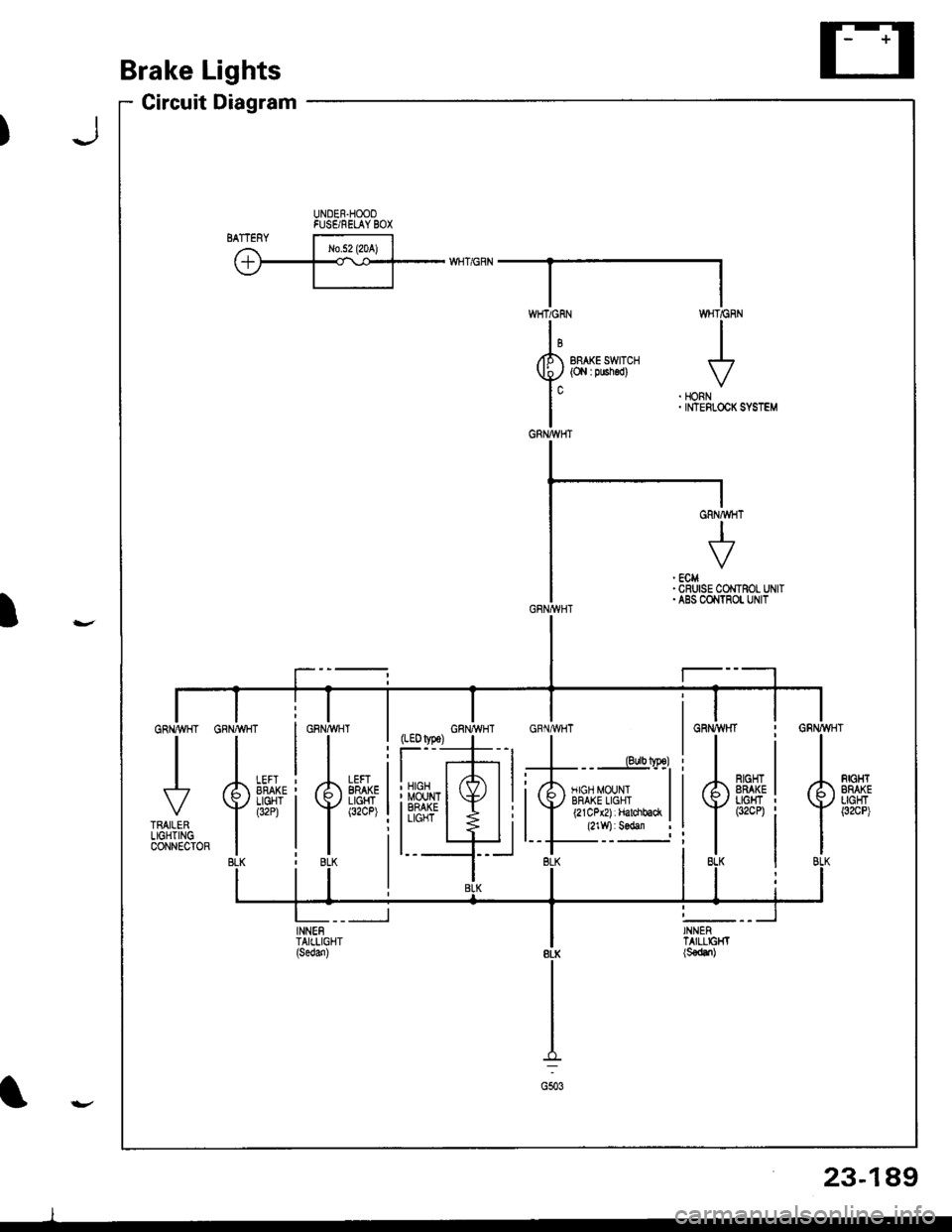
Brake Lights
Circuit Diagram
UNDER.HOOOFUSE/RELAY BOX'ry
BRAKE SWITCH(O,l I pushed)
WHT/GF
I
HONNINTEFLOCK
,#�,.^{.
LEFIBRAKELIGHT(32CP)il
:li
l_t
INNENTAIILIGHT
WHTiGRN
GRNA{HT
J
GRNMHT
23-189
l
I
Page 1250 of 1681
Circuit Diagram
UNDEB HOOD FUSUBELAY 8OX
N0.41 (100A) No.5l (l5A)
UNDER DASHFUSE/FELAY BOXCOMEINATIONLIGHT SWITCH
wHT ---{. rcr- RED/GRNV rclrrtor swror
WHT/BLK +WNTBLK/YEL
WHT/GRN
I GFNBLU GRIVBLU
-]JJ
IVVGRNIELU TRATLERI L|GHTINGI CONNECTOR
TRUN SIGNALswrTcHF (Not used)
GBN/ORN
GRNioRN-
GRNALU GRN/BLU
RED
tltl
rl
I
t
OASH LIGHTSBFIGHTNESSCONTROLLEH
*f --.f ,-+r*n"+
RN/YE
t
TBLK
GRN,YEL
tttol
I RE,
lo'8LK
8LK
I
G201G401
GFN/BLU
)
23-193
Page 1255 of 1681
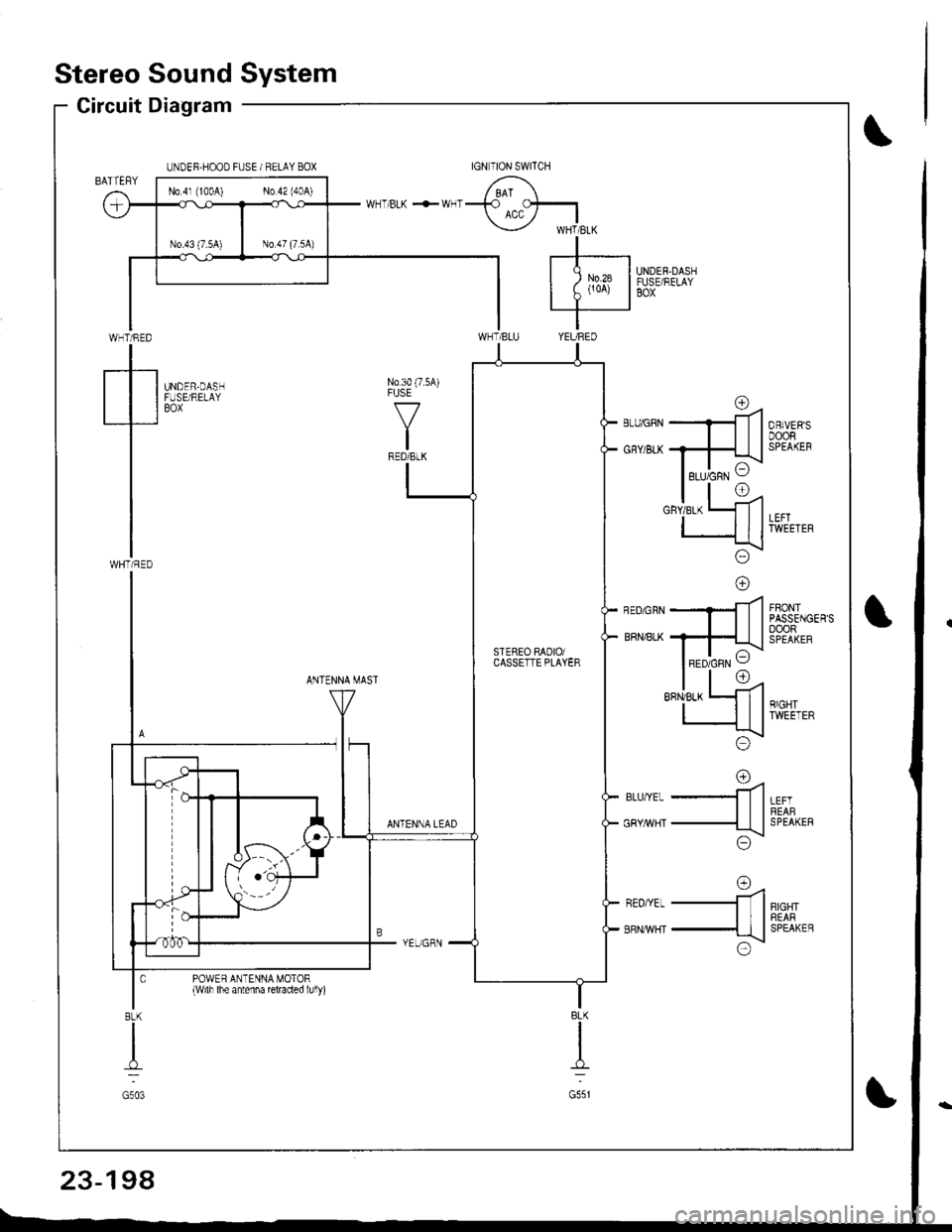
Stereo Sound System
Circuit Diagram
WHT/RED
tWHTi RED
UNDER.HOOD FUSE / RELAY BOX
UNDER.DASHFUSE/RELAYBOX
N0.30 (7.5A)FUSE
f7
IRED/BLK
UNDER,DASHFUSE/RELAYBOX
FRONTPASSENGER'SoooRSPEAKER
ANTENNA MAST
LEFTREABSPEAKER
RIGHTREARSPEAKEB
rna-ll
-ttl
;\\:/
o=4-ll
-{tl
x!\:/
ANTENNA LEAD
BLU,YEL
GRY/rrVHT
REO/YEL
ERNMHT
POWER ANTENNA MOTOR{wilh lhe antenna reraded lully)
BLK
I
G551
8LK
I
G503
No 4l (100A) No 42 (40A)
rc\RED/GRN VSTEBEO RADIOiCASSETTE PLAYER
23-198


![HONDA INTEGRA 1998 4.G Owners Manual Gircuit Diagram
UNDEF.HOOD FUS gRELAY BOX
(Wilh moonrool)-l
,,**Er
WHT/FED
LT
]NTEGRATED TCoNTROL IUNIT I
lSedan)
.-l
TRUNKL]GHT(sw)
I
lff
lh
iT
Lir -
lb
.F
23-141 HONDA INTEGRA 1998 4.G Owners Manual Gircuit Diagram
UNDEF.HOOD FUS gRELAY BOX
(Wilh moonrool)-l
,,**Er
WHT/FED
LT
]NTEGRATED TCoNTROL IUNIT I
lSedan)
.-l
TRUNKL]GHT(sw)
I
lff
lh
iT
Lir -
lb
.F
23-141](/img/13/6069/w960_6069-1237.png)
![HONDA INTEGRA 1998 4.G Owners Manual Back-up Lights
Circuit Diagram
IGNITIONswlTcHUNOER.HOOD FUSEi RELAY BOX
EACK.UPLIGHTswtTcH/ / on lhe \r I ransnBgon I
GRN/BLK
IIJ
TRAILERL]GHT NGCONNECTOR
GRN/BLK
IzA arcx.upI P LIGHTS
f
r:zce21
I HONDA INTEGRA 1998 4.G Owners Manual Back-up Lights
Circuit Diagram
IGNITIONswlTcHUNOER.HOOD FUSEi RELAY BOX
EACK.UPLIGHTswtTcH/ / on lhe \r I ransnBgon I
GRN/BLK
IIJ
TRAILERL]GHT NGCONNECTOR
GRN/BLK
IzA arcx.upI P LIGHTS
f
r:zce21
I](/img/13/6069/w960_6069-1243.png)
![HONDA INTEGRA 1998 4.G Owners Manual Circuit Diagram
UNDEB HOOD FUSUBELAY 8OX
N0.41 (100A) No.5l (l5A)
UNDER DASHFUSE/FELAY BOXCOMEINATIONLIGHT SWITCH
wHT ---{. rcr- RED/GRNV rclrrtor swror
WHT/BLK +WNTBLK/YEL
WHT/GRN
I GFNBLU GRIVBLU
-] HONDA INTEGRA 1998 4.G Owners Manual Circuit Diagram
UNDEB HOOD FUSUBELAY 8OX
N0.41 (100A) No.5l (l5A)
UNDER DASHFUSE/FELAY BOXCOMEINATIONLIGHT SWITCH
wHT ---{. rcr- RED/GRNV rclrrtor swror
WHT/BLK +WNTBLK/YEL
WHT/GRN
I GFNBLU GRIVBLU
-]](/img/13/6069/w960_6069-1249.png)
