instrument panel HONDA INTEGRA 1998 4.G Workshop Manual
[x] Cancel search | Manufacturer: HONDA, Model Year: 1998, Model line: INTEGRA, Model: HONDA INTEGRA 1998 4.GPages: 1681, PDF Size: 54.22 MB
Page 421 of 1681
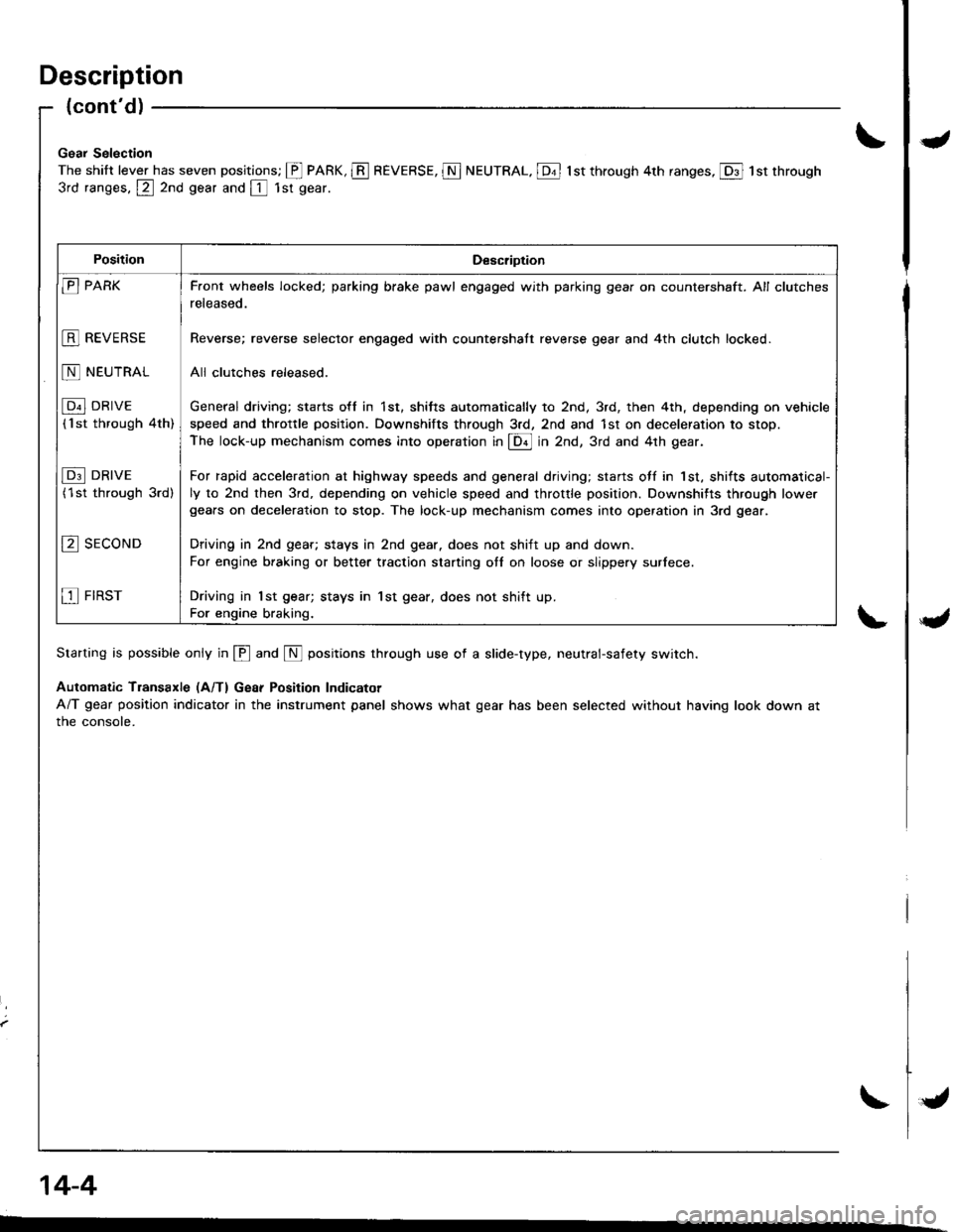
Description
{cont'd)
Gsar Selection
The shift lever has seven positions; @ PARK, E REVERSE, N NEUTRAL. [Dt l st through 4th ranges, @ 1st through
3rd ranges, @ 2nd gear and [ 1sr gear.
Starting is possible only in @ and N positions through use of a slide-type, neutral-safety switch.
Automatic Transaxle (A/T) Gear Position Indicator
A/T gear position indicator in the instrument panel shows what gear has been selected without having look down at
the console.
PositionDescription
E PARK
E REVERSE
N NEUTRAL
[p"l DRrvE
('lst through 4th)
I p3l DRrvE
(1st through 3rd)
E sEcoND
E FIRST
F.ont wheels locked; parking brake pawl engaged with parking gear on countershaft. All clutches
released.
Reverse; reverse selector engaged with countershatt reverse gear and 4th clutch locked.
All clulches released.
General driving; sta.ts o{f in 1st, shitts automatically to 2nd, 3rd, then 4th, depending on vehicle
speed and throttle positlon. Downshifts through 3rd, 2nd and 1st on deceleration to stop.
The lock-up mechanism comes into operation in @ in Zna, 3rd and 4th gear.
For rapid acceleration at highway speeds and general driving; starts otf in 1st, shifts automatical-
ly to 2nd then 3rd, depending on vehicle speed and throttle position. Downshifts through lowe.gears on deceleration to stop. The lock-up mechanism comes into operation in 3rd gear.
Driving in 2nd geat; stays in 2nd gear. does not shift up and down.
For engine braking or better traction starting otl on loose or slippery surlece.
Driving in 1st gear; stays in 1st gear, does not shift up.
For engine braking.
14-4
{
Page 676 of 1681
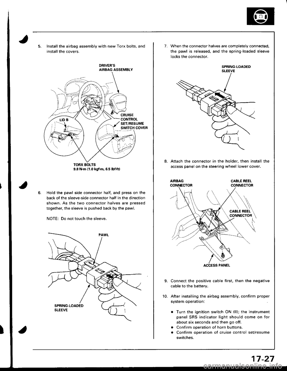
Installthe airbag assembly with new Torx bolts, and
installthe covers.
cRursECONTROLSET/RESUMEswtTcH covER
Hold the pawl side connector half. and press on the
back of the sleeve-side connector halt in the direction
shown. As the two connector halves are pressed
together, the sleeve is pushed back by the pawl.
NOTE: Do not touch the sleeve.
7.When the connector halves are completely connected.
the pawl is released. and the spring loaded sleeve
locks the connector.
SPRING.LOADEDSLEEVE
Attach the connector in the holder, then install the
access panel on the stee.ing wheel lower cover.
Connect the positive cable first. then the negative
cable to the battery.
After installing the airbag assembly, confirm proper
system operation:
. Turn the ignition switch ON (ll); the instrument
panel SRS indicator light should come on for
about six seconds and then go off.
. Confirm operation of horn buttons.
. Confirm operation of cruise control sevresume
switches.
10.
17-27
Page 948 of 1681
Dashboard
Component Removal/lnstallation
\J
U
uomponenl r{emoval/ Insrallarlon -
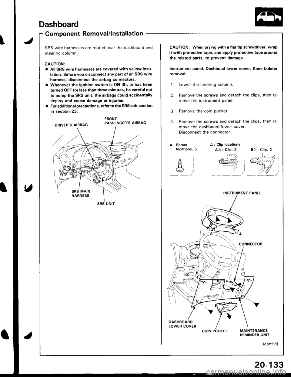
SRS wire harnesses are routed near the dashboard and
sreenng corumn.
CAUTION:
a AIISRS wire harnesses are cove.ed with yellow insu-
lation. Belore you disconnect any part of an SRS wire
hahess, disconnect the airbag connectors.
o Whenever the ignition switch is ON (ll), or has been
turned OFF fol less than three minutes, be caretul not
to bump the SRS unit; the airbags could accidentally
deploy and cause damage or inturies.
a For additional precautions, reJer to the SRS sub-section
in section 23.
FRONTPASSENGER'S AIRBAG
SRS UNIT
CAUTION: When prying with a flat tip screwdriver, wrap
it with protective tape, and apply proteclive tape around
the related parts, to prevent damage,
Instrument panel, Dashboad lower cover, Knee bolster
temovat:
1. Lower the steering column.
2. Remove the screws and detach the clips, then re-
move the instrument panel.
3. Remove the coin pocket.
4. Remove the screws and detach the clips, then re
move the dashboard lower cover.
Disconnect the connector.
A : Screwlocations,5A i Clip locations
AA: Clip, 2 B> : Clip, 2
INSTRUMENT PANEL
ii'- ' iq4'ii \Ll1
COIN POCKET
(cont'd l
20-133
Page 1183 of 1681
1.
2.
Gauge Assembly
Removal
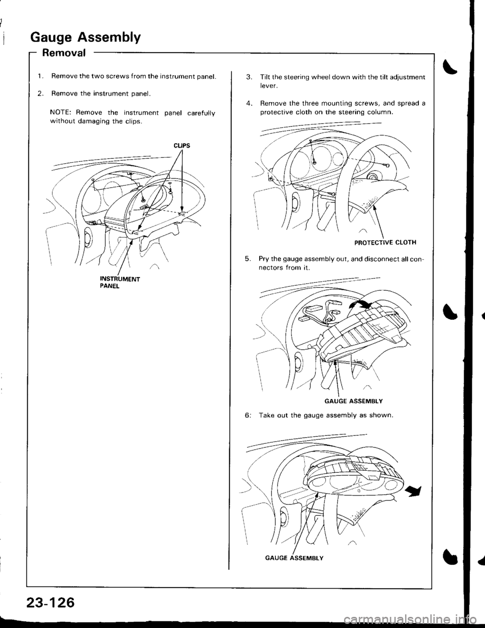
Remove the two screws from the instrument panel.
Remove the instrument panel.
NOTE: Remove the instrument panel carefully
without damaging the clips.
23-126
3.
5.
Tilt the steering wheel down with the tilt adjustment
lever.
Remove the three mounting screws, and spread a
protective cloth on the steering column.
PROTECTIVE CLOTH
Pry the gauge assembly out, and disconnect all con
nectors from it.
6:
GAUGE ASSEMBLY
Take out the gauge assembly as shown.
GAUGE ASSEMBLY
Page 1236 of 1681
J
)
'1.
3.
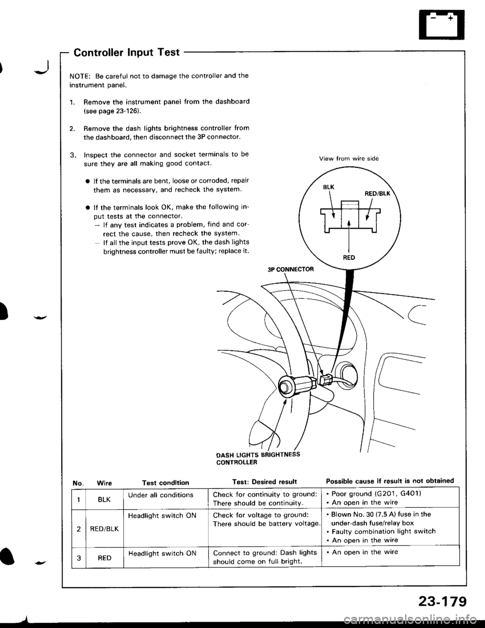
NOTE: Be careful not to damage the controller and the
instrument panel.
Remove the instrument panel from the dashboard
(see page 23-126).
Remove the dash lights brightness controller from
the dashboard, then disconnect the 3P connector.
Inspect the connector and socket terminals to be
sure they are all making good contact.
a lf the terminals are bent, loose or cortoded, repair
them as necessary, and recheck the system.
a It the terminals look OK, make the following in-
put tests at the connector.- lf any test indicates a problem, find and cor
rect the cause, then recheck the system.
It all the input tests prove OK, the dash lights
brightness controller must be faulty; replace it.
3P CONNECTOR
View lrom wire side
Possible cause if result is not obtainedNo.WireTest condition
CONTROLLEB
Test: Desired resull
BLK
REO
BLKUnder all conditionsCheck for continuity to ground:
There should be continuity.
. Poor ground (G201 , G4O1l. An open in the wire
2REDi BLK
Headlight switch ONCheck for voltage to ground:
There should be battery voltage
Blown No.30 (7.5 A) fuse in the
under-dash fuse/relay box
Faulty combination light switch
An open in the wire
3REDHeadlight switch ONConnect to ground: Dash lights
should come on full bright.
. An open in the ware
l-
)
23-179
Page 1271 of 1681
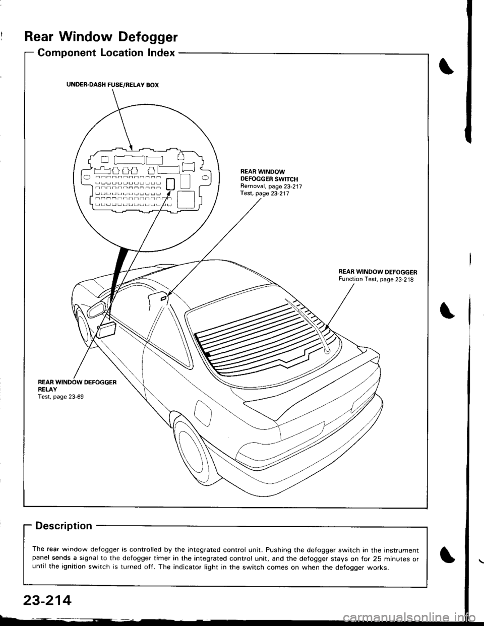
Rear Window Defogger
Component Location Index
Description
The rear window de{ogger is controlled by the integrated control unit. Pushing the detogger switch in the Instrumentpanel sends a signal to the defogger timer in the integrated control unit, and the defogger stays on for 25 minutes oruntil the ignition switch is turned off. The indicator light in the switch comes on when the defogger works.
UNDER.OASH FUSE/RELAY BOX
r-'luijij u lNEAR WINDOWDEFOGGER SWITCHRemoval, page 23-217Test, page 23 217
REARDEFOGGERREI-AYTest, page 23-69
23-214
Page 1316 of 1681
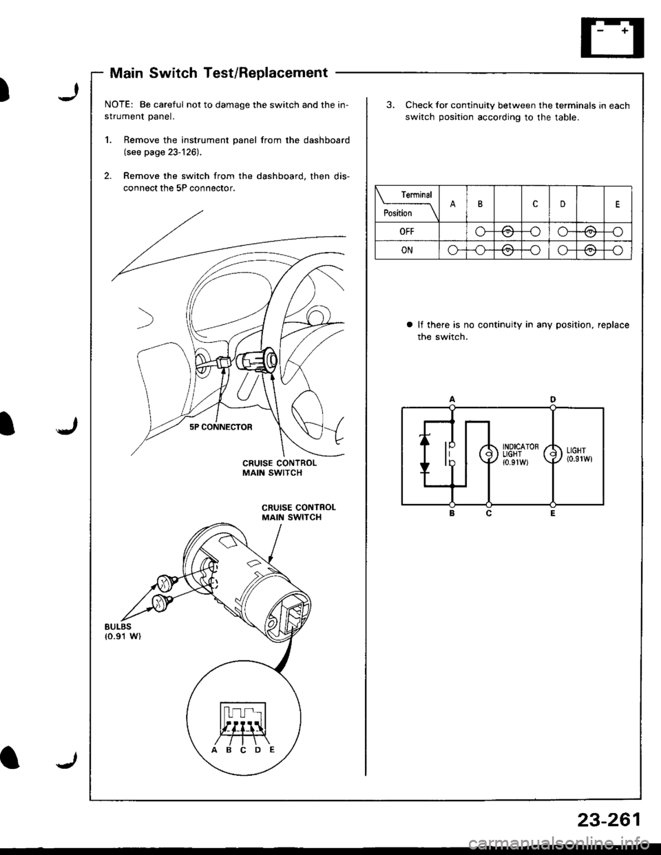
Main Switch Test/Replacement
J)
JI
I
NOTE: Be careful not to damage the switch and the in-
strument panel.
1. Remove the instrument panel from the dashboard(see page 23-126).
2. Remove the switch from the dashboard. then dis-
connect the 5P connector,
3. Check for continuity between the terminals in each
switch position according to the table.
a lf there is no continuity in any position, replace
the switch.
Teminal
;""Jt- \ttcD
OFFo-/a\-o/.:\-o\:.7\:./
ONo*/:\-oo--o\:,,/\-/
ABCDE
J
23-261