jump start HONDA INTEGRA 1998 4.G Workshop Manual
[x] Cancel search | Manufacturer: HONDA, Model Year: 1998, Model line: INTEGRA, Model: HONDA INTEGRA 1998 4.GPages: 1681, PDF Size: 54.22 MB
Page 255 of 1681
I
I
It:
PGM-FI System
Engine Control Module {ECMI
,i
I
{
ili
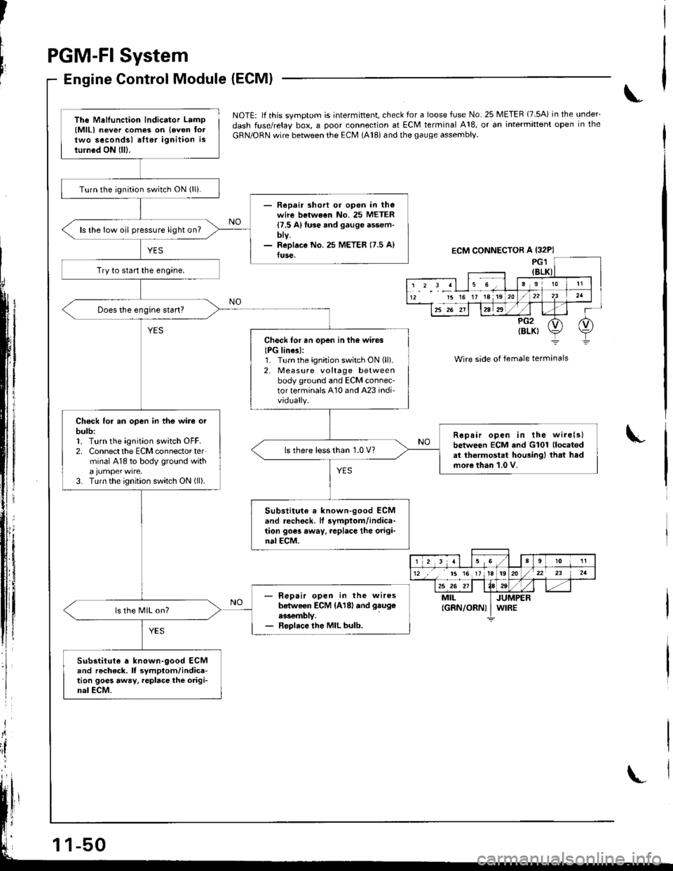
NOTE: lf this svmotom is intermittent, check for a loose fuse No. 25 METER (7.5A) in the under_
dash fuse/relay box, a ooor connection at ECM terminal A18, or an intermittent open in the
GRN/ORN wire between the ECM (A18) and the gauge assembly.
Wire side of female terminals
I
The Mellunction Indicator Lamp(MlLl never com€3 on leven foltwo secondsl alter ignition islurn6d ON lll).
Turn the ignition switch ON (lli.
- Repair short or open in th€wire betwe€n No. 25 METER{7.5 A}fuse and gauge assem-bty.- ReDlaco No.25 METER 17.5 A)fuse.
ls the low oil pressure light on?
Try to start the engine,
Check for an open in ih6 wires
IPG lines):1. Turnthe ignition switch ON (ll).
2. Measure voltage betweenbody ground and ECM connec-tor terminals A10 and A23 indi-vidually.
Chock for an open in the wire orbulb:1. Turn the ignition sw;tch OFF.2. Connectthe ECM connector terminal 418 to body ground with
3. Turn the ignition switch ON (ll).
Repair open in the wire(slbetween ECM and G101 (located
at thermostat housingl that hadmore than 1.0 V.
ls there less than 1.0 V?
Substitute . known-good ECMand .echeck, lf symptom/indica-tion goes away, replace the origi-nalECM.
- R€pair open in the wiresb€tweon ECM {A18land gaug€
ess€mbly.- Replace the MIL bulb.
ls the MIL on?
Substitute a known-9ood ECMand rech6ck. It symptom/indica-tion goes away, repbce the origi-nal ECM.
ECM CONNECTOR A {32P)
15 16 17 18 19
r 2 3 al 15 Ga910 11
12 ,, t5 16 1tt920/22 23 2a
25 26 211184tt-MILJUMPER(GRN/ORN) I WIRE
Page 261 of 1681
PGM-FI System
Manifold Absolute Pressure (MAPI Sensor (cont'dl
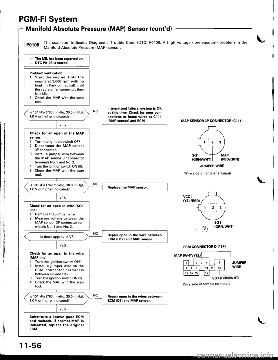
tF'r'sl li:"J:ilfi::il***:ilHi""k:"
code (Drc) P0108' A hish vo*ase (row vacuum) probrem in the
Thc MIL has b6en reoortod on.OTC P0108 is stored.
Problem veritication:1. Start the engine. Hold theengine at 3,000 rpm with noload (in Park or neutral) untilthe radiator fan comes on, thenlet it idle.2. Check the MAP wlth the scantool,
Intermittent f.ilure, svstem is OKal this time. Check lor Door con-nections or loose wires at C114{MAP sensor} and ECM.
ls 101 kPa (760 mmHg,30.0 in.l-lg),1.0 V or higher indicated?
Chock tor an opcn in th. MAPs€nsoa:1. Turn the ignition switch OFF.2. Disconnect the MAP sensor3P connector.3. Install 6 jumper wire betweenthe MAP sensor 3P connectorterminals No.3 and No.2.4. Turn the ignition switch ON (ll).
5. Ch€ck the MAP with the scantool.
ls 101 kPa (760 mmHg,30.0 in.Hg),1.0 V or higher indicated?
Check tor an open in wire (SG1
linel:1. Remove the jumper wire.2, Measure voltage between theMAP sensor 3P connector teFminals No. I and No.2.
Repair open in the wire betweenECM l012l and MAP s€nsor.ls there approx.5 V?
Check for an open in the wire{MAP line):1. Turn the ignition switch OFF.2. Install a jumper wire on theECM co n nector terminalsbetween D3 and Dl2.3. Turn the ignition switch ON lll).4. Check the MAP with the scantool,
ls 101 kPa (760 mmHg,30.0 in.Hg),1.0 V or higher indicated?Repair open in the wires betweenECM {D3, and MAP s6Gor.
Substitut€ a known-good ECMand recheck. It normal MAP isindicaied, rgplace the originalECM.
MAP SENSOR 3P CONNECTOR {C114}
Wire side of female terminals
L
vccr{YEL/RED)
MAP IWHT
JUMPERWIRE
SG1 (GRN/WHT}
Wire side of female terminals
1 1-56
{GRN/WHT)I ] {RED/GRN)
ECM CONNECTOR D {16P}
L
Page 274 of 1681
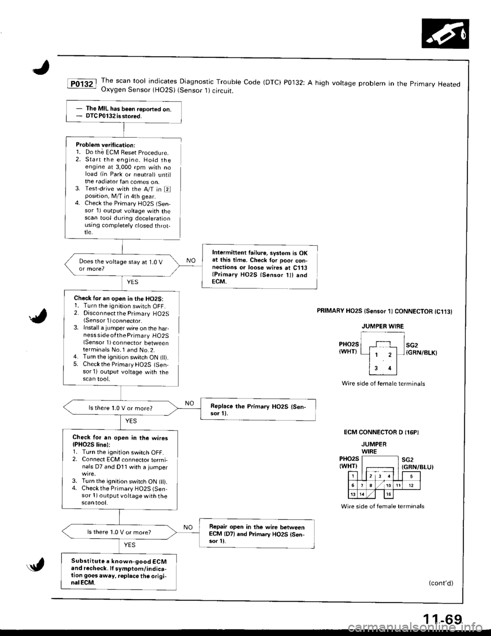
JThe scan tool indicates Diagnostic Trouble Code (DTC) P0132: A high voltage probtem in the primary HeatedOxygen Sensor (HO2S) (Sensor 1) circuit.
Problem veritication:1. Do th; ECM Reset procedure.
2. Start the engine. Hold theengine at 3,000 rpm with noload (in Park or neutral) untilthe radiator fan comes on,3. Test-drive with the A/T in Elposition, M/T in 4th gear.4. Check the Primary l-lO2S (Sen-sor 1) outprrt voltage with thescan tool during decelerationusrng comptetely closed throt-tle.
YES
Check tor an open in the HO2S:1. Turn the ignition switch OFF.2. Disconnectthe Primary HO2S(Sensorl)connector.
lnstall a jumper wire on the harness side ofthe Primary HO2S(Sensor 1) connector betweenterminals No.1 and No.2.Turn the ignition switch ON t).Check the Prjmary HO2S (Sen-sor'l) output voltage with thescan tool.
Intermittent failur€, svstem is OKat this time. Check for poor con-nectaons or loose wires at C113(Primary HO2S lsensor lll andECM.
5.
PRIMAnY HO2S {Sensor 1) CONNECTOR tC1t3l
PHO2S(WHT}
Wire side of female terminals
ECM CONNECTOR D (16PI
JUMPERWIREPHO2S(WHT)F;r=12 3 !l
sG2
5
./ 1012
13
(GBN/BLU)
Wire side of female terminals
(cont'd )
- The MIL has b€€n ieDorted on.- DTC P0132 isstored.
Replace the Primary HO2S (Sen-sor 11.ls there 1,0 V or more?
Check for an open in the wiros{PHO2S lin6):1. Turn the ignition switch OFF.2. Connect ECM connector termi-nals D7 and Dl1 with a jumper
3. Turn the ignition switch ON 0).4. Checkthe Primary HO2S (Sen-sor 1) output voltage with thescantool.
Repair open in the wire betweenECM (D7) end Primarv HO2S lsen-sor l).
ls there 1,0 V or more?
Substitute a known-good ECMand recheck. lf symptom/indica-tion goesaway. r€place th€ origi-nalECM.
1 1-69
Page 277 of 1681
PGM-FI System
Secondary Heated Oxygen Sensor (HO2S) (Sensor 2l (cont'd)
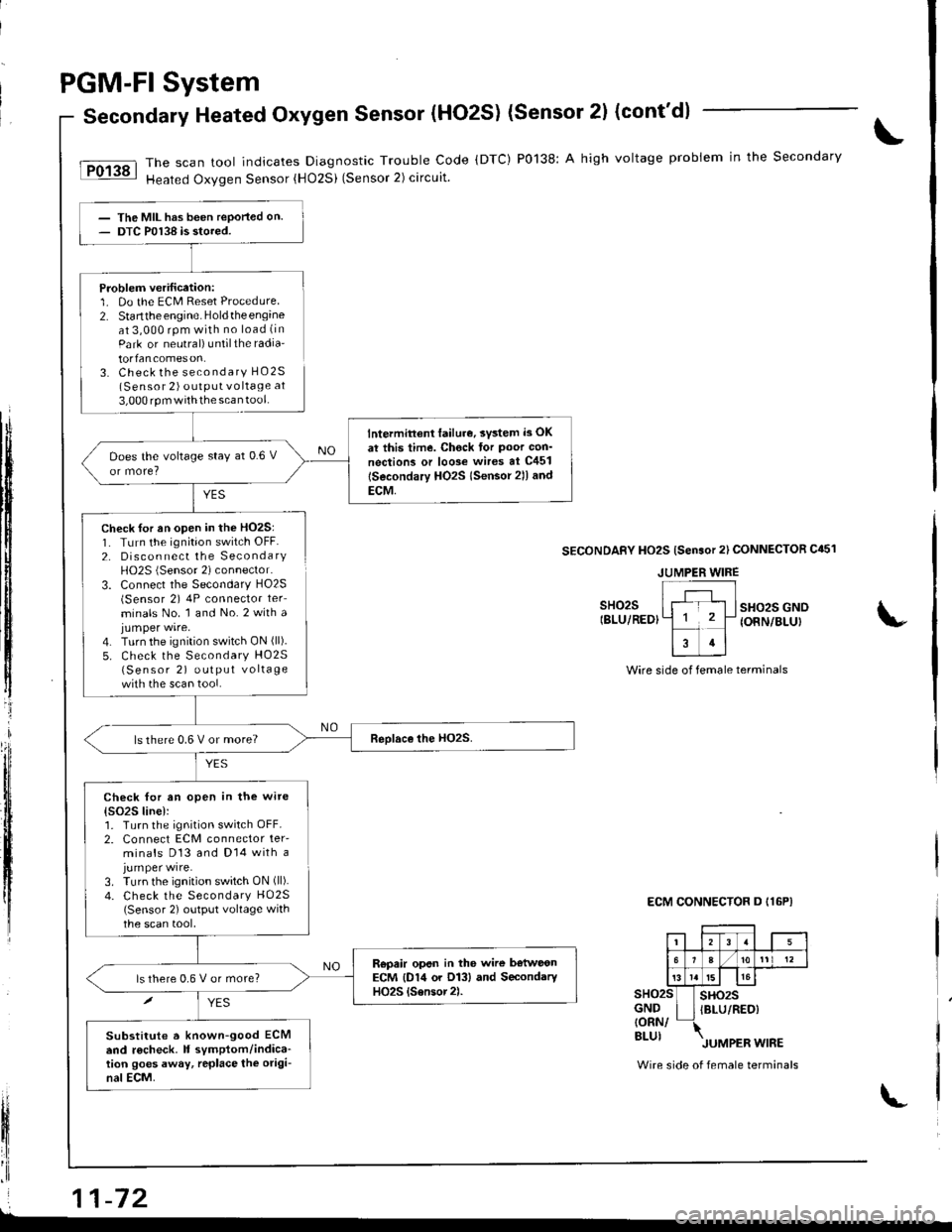
The scan tool indicates Diagnostic Trouble Code (DTC) P0138: A high voltage probiem in the Secondary
Heated Oxygen Sensor {HO2Si (Sensor 2) circuit.
YES
The MIL has been reported on.DTC P0138 is stored.
Problem verification:1. Do the ECM Reset Procedure2. Startthe engine. Holdtheengineat 3,000 rpm with no load (in
Park or neutral) untilthe radia'
torfancomeson.3. Check the secondary HO2S(Sensor 2) outPUt vo ltage at
3,000 rpm withthe scan tool.
lntermittent lailur€, svsted i3 OK
at this time. Chock tor Poor con'
nections or loo3e wires at C451
lSecondary HO2s lsensor 2ll and
ECM,
Does the voltage stay at 0.6 V
ls there 0.6 V or more?
Check for an open in the wite
{s()2S line):1. Turn the ignition switch OFF.2. Connect ECM connector ter-minals D13 and Dl4 with ajumper wire.3. Turn the ignition switch ON (ll).
4. Check the Secondary HO25(Sensor 2) output voltage withthe scan tool,
Repair opsn in the wire b€tweonECM {D14 or O13} and SecondaryHO2S {Sensor2).ls there 0,6 V or more?
Substitute a known-good ECMend r6check. It symptom/indica-tion goes away, rcplace the origi-nal ECM.
tI
t$
ffi
tljl'l
t,
lfi
il
fl'I
Check for an open in the HO2S:1. TLrrn the ignition switch OFF.2. Disconnect the SecondaryH02S (Sensor 2) connector.
3. Connect the Secondary HO2S(Sensor 2) 4P connector ter_
minals No. 1 and No.2 with ajumper wire.4. Turn the ignition switch ON (ll).
5. Check the Secondary HO25(Sensor 2) output vo lta ge
with the scan tool.
SECONDAFY HO2S {Sensor 2l CONNECTOR C451
sHo2sIBLU/REDIsHo2s GNOIONN/BLUI
Wire side of female terminals
ECM CONNECTOR D I16P}
sHo2sGND{ORN/BLUI
sHo2sIBLU/RED)
Wire side of female terminals
JUMPER WIRE
i 11-72L
Page 306 of 1681
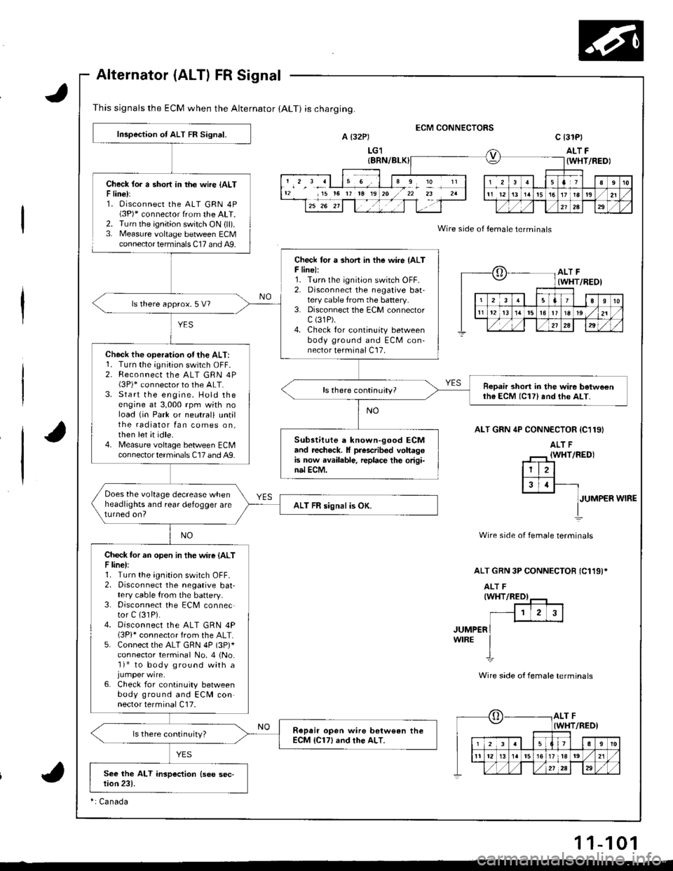
This signals the ECM when the Alternator (ALT) is charging.
Alternator (ALT) FR Signal
Check lor a short in th€ wire {ALTF line):1. Oisconnect the ALT GRN 4P(3P)* connector from the ALT.2. Turn the ignition switch ON {ll).3. Measure voltage between ECMconnector terminals C17 and A9.
ECM CONNECTORSA t32Pt
LG1
c 13lPl
ALT F(WHT/FEDI
Wire side of female terminals
ALT GRN 4P CONN€CTOR {C119}
JUMPER WIRE
Wire side of female terminals
ALT GRN 3P CONNECTOB {C119)*
JUMP€RWIRE
Wire side ot female terminals
12 15 t6 rr t8 19I
?
oALT F(WHT/REOI
23aI10
t112t3t5l6r819 ,/21
./,/,/2a29
[,ALT FIWHT/RED)
12339
11 12l517 tla19 ,/21
Inspection of ALT FR Signal.
Check for a shon in the wire {ALTF line):1. Turn the ignition switch OFF.2. Disconnecl the negative baatery cable from the battery.3. Disconnect the ECM connectorc (31P).
4. Check for continuity betweenbody ground and ECM con-nector terminal C17.
ls there approx.5 V?
Check the operation ofthe ALT:1. Turn the;Onition switch OFF-2. Reconnect the ALT GRN 4P(3P)* connector to the ALT.3. Start the engine. Hold theengine at 3,000 rpm wkh noload {in Park or neutral) untilthe radiator fan comes on,then let it idle.4. Measure voltage bet/veen ECMcon nector termina ls C17 and A9.
Ropair short in the wir6 betweenth6 ECM (C17) and the ALT.
Substitute a known-good ECMand recheck. It prescribed voltagGis now available, replace th€ origi-nal ECM.
Does the voltage decrease whenheadlights and rear defogger areturned on?ALT FR signal is OK.
Check tor an open in the wire {ALTF line):1. Turn the ignition switch OFF-2. Disconnect the negative bat-tery cable from the battery.3. Disconnect the ECM connector C (31P).
4. Disconnect the ALT GRN 4P(3Pi* connector from the ALT.5. Connect the ALT GRN 4P (3p)*
connector terminal No. 4 (No.'l)* to body ground with a
6. Check for continuity betweenbody ground and ECM connector terminal C17.
Ropair open wire bstw€an theECM {C17} and rhe ALT.ls there continuity?
ri Canada
11-101
Page 308 of 1681
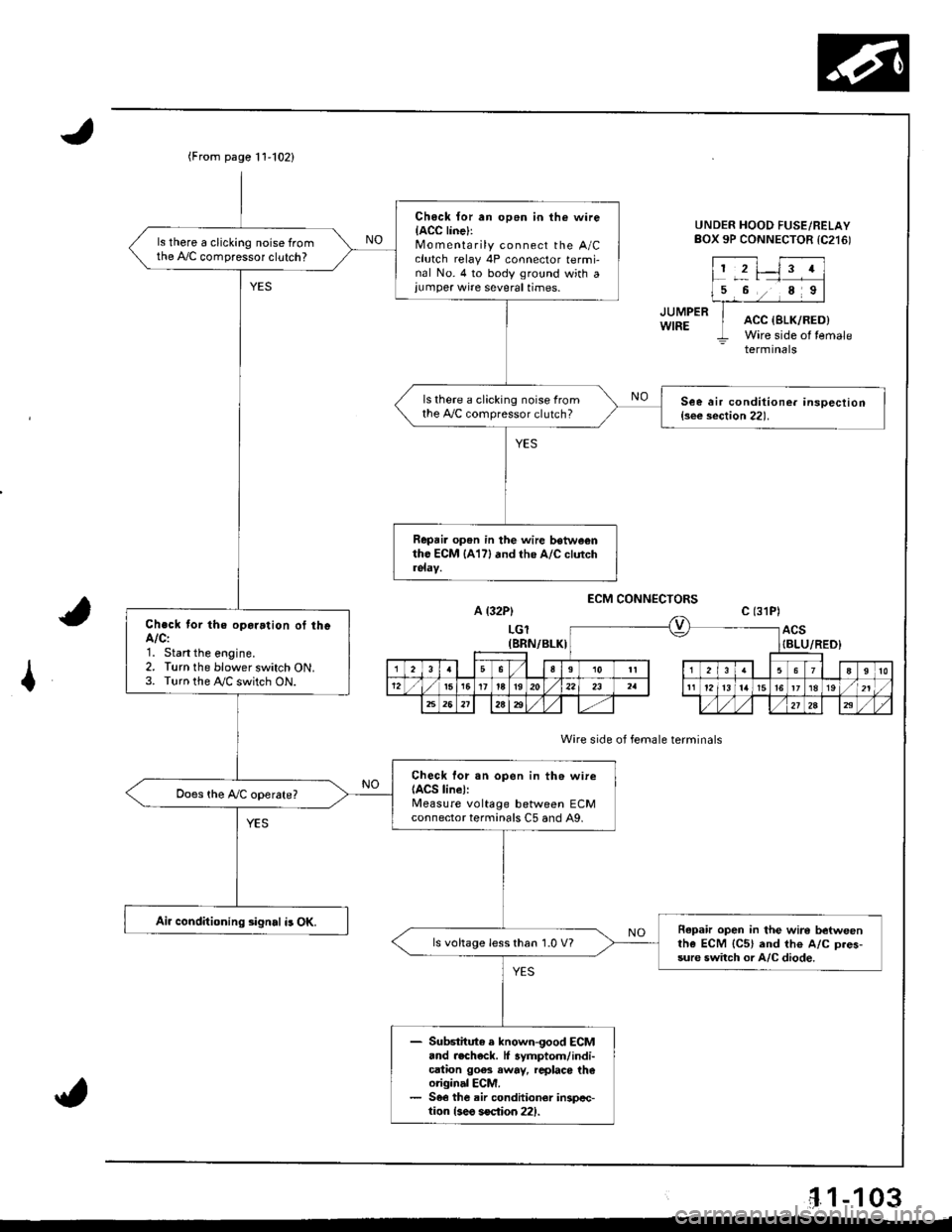
(From page t 1'102)
Ch6ck {or an op6n in the wireIACC linel:Mo m enta rily connect the A/Cclutch relay 4P connector termi-nal No. 4 to body ground with a,umper wire several times.
ls there a clicking noise fromthe A,/C compressor clutch?
ls there a clicking noise fromthe 4,./C compressor clutch?See air conditione. insoection{s€e section 22).
Repai. op6n in the wire betwe€ntho ECM lA17l and the A/C clutch
Check tor the oparation of theA/C:1. Start the eogine.2. Turn the blower switch ON.3. Turn the !y'C switch ON.
Check lor sn open in th6 wireIACS line):Measure voltage between ECMconnector terminals C5 and A9,
Air conditioning signal i3 OK.Repafu open in the wire betweenthe ECM {C5} and th€ A/C D.es-sure switch or A/C diode.
ls voltage less than 1.0 V?
- Substitute e known-good ECM.nd .echeck. lf 3ymptom/indi-cation goes away, rcplaco th€original ECM.- 56€ the air conditionor inspcc-tion {3eo soction 221.
UNDER HOOD FUSE/RELAYBOX 9P CONNECTOR tC216)
JUMPERWIREACC {SLK/RED)Wire side of temale- terminals
A {32P)
LGl(BRN/BLKI
ECM CONNECTORS
Wire side of female terminals
c (31P)
ACS{BLU/RED}
I
'1.1-103
Page 804 of 1681
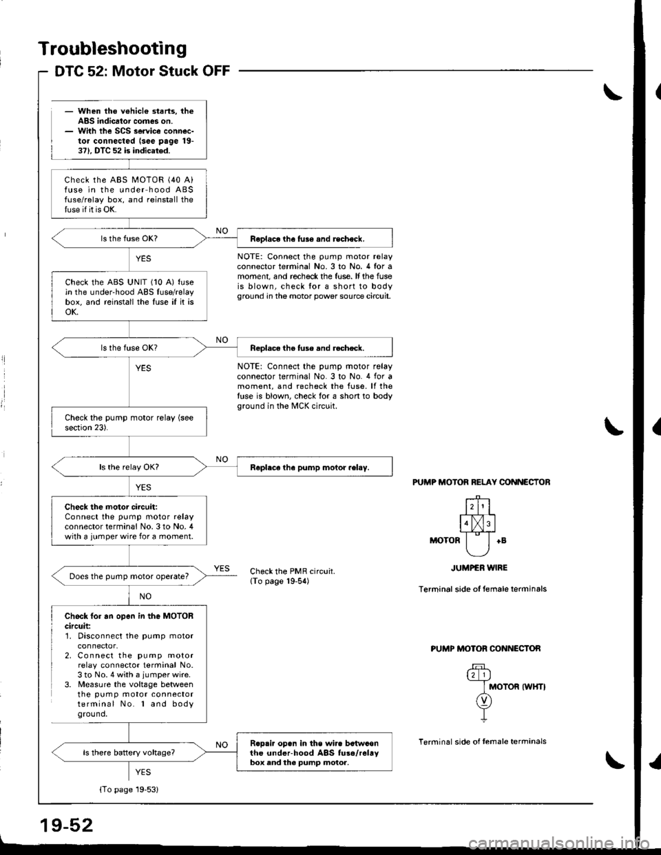
Troubleshooting
- When the v€hicl€ starts, theABS indicator comes on.- With the SCS service connec-tor connected lsee page 19-371. DTC 52 is indicated.
DTC 52: Motor Stuck OFF
l
l
NOTE: Connect the pump motor relayconnector terminal No.3 to No. 4 for amoment, and rechock the fuse. It the fuseis blown, check lor a short to bodyground in the motor power source circuit.
NOTE: Connect the pump motor relayconnector terminal No. 3 to No. 4 for amoment, and recheck the fuse. lf thetuse is blown, check for a short to bodyground in the MCK circuit.
PUTIIP MOTOR RELAY CONNECTOB
+B
Check the PMR circuit.lTo page 19-54)
JUMPER WIRE
Terminal side of temale terminals
Check fo. an open in the MOTORcircuit:1. Disconnect the pump motor
2. Connect the pump motorrelay connector terminal No.3 to No. 4 with a jumper wire.3. Measure the voltage betweenthe pum p motor connectorterminal No. l and bodyground,
PUMP MOTOR CONNECTON
u_l_lj
I MOTOR tWHTt
n)Y-L
Terminal side of temale terrninals
YES
Check the ABS MOTOR (40 A)fuse in the under hood ABSfuse/relay box, and reinstall thetuse if it is OK.
Feplace the fus6 and recheck.
check the ABS uNlT (10 A) fusein the under-hood ABS fuse/relaybox, and reinstall the fuse if it isoK.
Reolace the tuse and r.check.
Roplece tha pump motor .el.y.
Check the motor circuit:Connect the pump motor relayconnector terminal No. 3 to No, 4with a jumper wire for a moment.
Does the pump motor operate?
Rop.i. opan in the wir. betwconthc underhood ABS fuso/r6ltybox and the pump motor,
{To page 19-53}
Page 806 of 1681
Troubleshooting
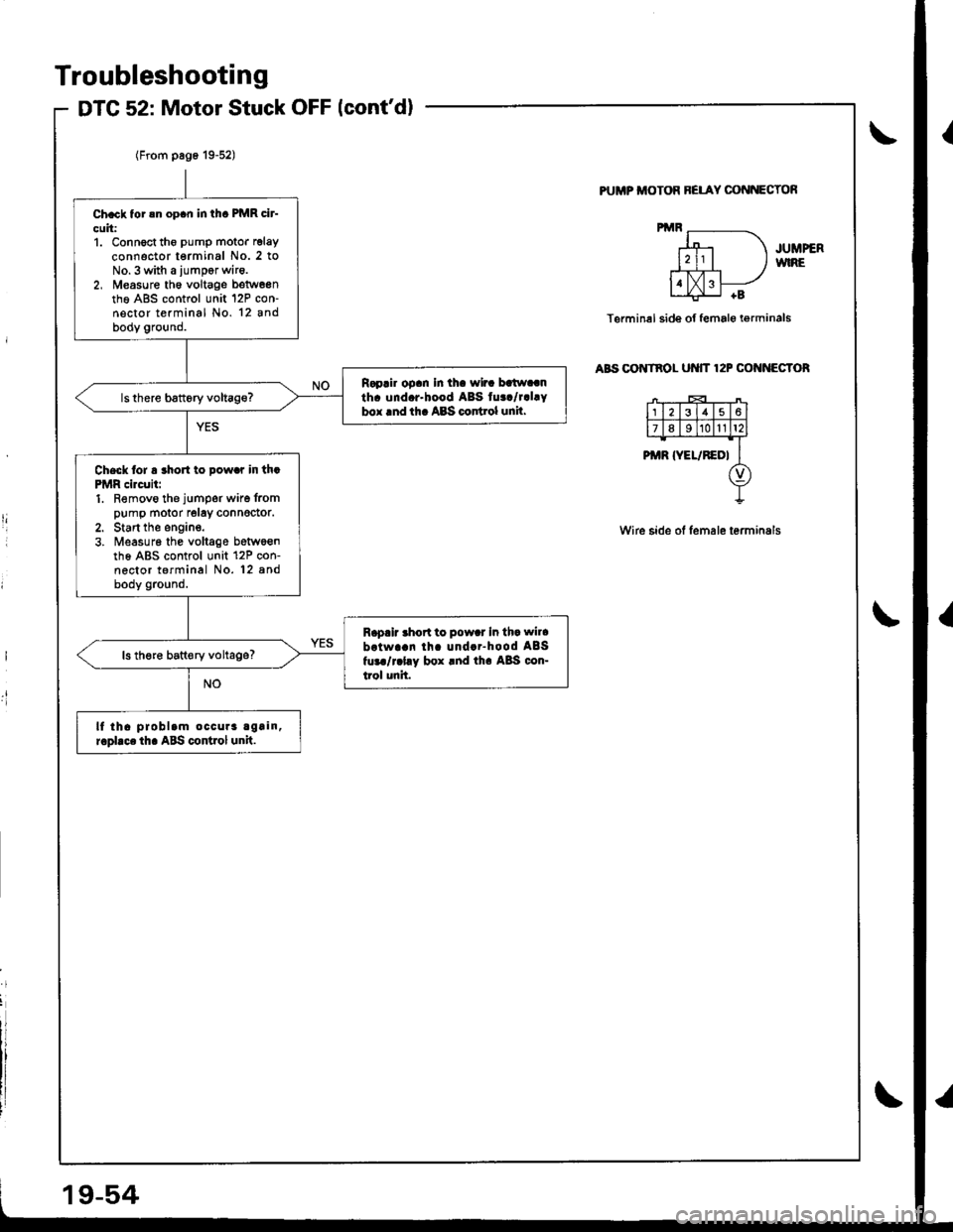
DTG 52: Motor Stuck OFF lcont'd)
PUMP ITIOTOR BELAY CONNECTOf,
JUMPERWIRE
Terminel side of female i€rminals
aBs oo tnol ut{tT 12P cof{f{EGToR
Wire side of lemale terminals
I
.t!
Ch.ck tor !n op.n in thc PMR cir-
cuit:1. Connoct tho pump motor relay
connector terminal No. 2 toNo.3 with a iumpor wir6.2, M€asure th6 voltage betw6entho A8S control unit 12P con-nector terminal No. 12 andbody ground.
R.p.ir op.n In th. wir. batw..nth. und.r-hood ABS tu../r.l.Ybox lnd th. ABS codrol unil.
Check lor a rho to pow.r in th.PMR circuii:1. Removo the jumper wire frompump motor relay connedor.2. Start the engine.3. ireasur6 the voltage betwoenth6 ABS control unit 12P con-nector terminal No. 12 8ndbody ground.
R.p.ir .hort to pow.r In th. wil.
brtwa!n lh. und..-hood ABSfur./r.l.y box rnd th. A8S con-trol unit.
ls th€re batt€ry voltage?
lf tha problam occura again,r.pllce th. ABS control unit.
Page 1134 of 1681
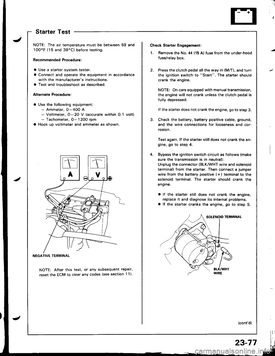
Ch6ck Starter Engag€mont;
1. Remove the No. 44 (15 A) fuse from the under-hood
fuse/relay box,
Press the clutch pedal all the way in (M/T), and turn
the ignition switch to "St8rt". The staner should
crank the engine,
NOTE: On cars equipped with manual transmission,
the engine will not crank unless the clutch pedal is
fully depressed.
lf the starter does not crank the engine, go to step 3.
Check the battery, battery positive cable, ground,
and the wire connections for looseness and cor-
rosion.
Test again. lf the stsner stilldoes not crank the en-
gine, go to step 4.
Bypass the ignition switch circuit as follows {make
sure the transmission is in neutral)
Unplug the connector (BLKMHT wire and solenoid
terminal) trom the staner. Then connect a jumper
wire from the batterv positive (+ ) terminal to the
solenoid terminal. The starter should crank the
engine.
a It the stsrter still does not crank the engine,
replace it and diagnose its internal problems,
a lf the starter cranks the engine. go to step 5.
(cont'd)
4.
NOTE: The air temperature must be between 59 and
100oF {15 and 38'C) betore testing.
Recommended Procedure:
a Use a starter system tester.
a Connect and operate the equipment in accordance
with the manufacturer's instructions.
a Test and troubleshoot as described.
Alternate Procodure:
a Use the following equipment;- Ammeter, O-400 A- Voltmeter. O-20 V (accurate within O,1 volt)- Tachometer, O- 1 2OO rpm
a Hook up voltmeter and ammeter as shown.
NEGATIVE TERMINAL
NOTE: Atter this test, or any subsequent repalr,
reset the ECM to clear any codes (see section 1 1).
StartelTest
23-77
Page 1191 of 1681
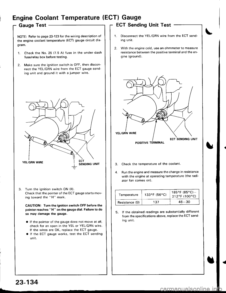
Engine Coolant Temperature (ECT) Gauge
Gauge Test
NOTE: Refer to page 23-123 for the wiring description of
the engine coolant temperature (ECT) gauge circuit dia-
gram.
1. Check the No. 25 (7.5 A) fuse in the under-dash
fuse/relay box before testing.
2. Make sure the ignition switch is OFF, then discon-
nect the YEL/GRN wire trom the ECT gauge send-
ing unit and ground it with a jumper wire.
YEL/GRN WIRESENDING UNIT
Turn the ignition switch ON (ll).
Check that the pointer of the ECT gauge starts mov-
ing toward the "H" mark.
CAUTION: Turn the ignition switch OFF before the
pointer reaches "H" on the gauge dial. Failure to do
so may damage the gauge.
a lf the pointer of the gauge does not move at all,
check lor an open in the YEL or YEL/GRN wire.
lf the wires are OK, replace the ECT gauge.
a lf the ECT gauge works, test the ECT sending
unrt.
ECT Sending Unit Test
Disconnect the YEL/GRN wire from the ECT send-
ing unit.
With the engine cold, use an ohmmeter to measure
resistance between the positive terminal and the en-
gine (ground).
Check the temperature ol the coolant.
Run the engine and measure the change in resistance
with the engine at operating temperature (the radi-
ator fan comes on).
5. It the obtained readings are substantially different
from the sDecifications above, replace the ECT send-
Ing unrt.
POSITIVE TERMINAL
Temperature133oF (56oC)1850F (85.C)-
212.F (100'C)
Resistance {O)13746-30
23-134