HONDA ODYSSEY 2018 Owner's Manual (in English)
Manufacturer: HONDA, Model Year: 2018, Model line: ODYSSEY, Model: HONDA ODYSSEY 2018Pages: 763, PDF Size: 47.02 MB
Page 721 of 763
719
uuIndicator, Coming On/BlinkinguIf the Brake System Indicator (Red) Comes On or Blinks at the Same Time When the Brake System Indicator (Amber) Comes On
Handling the Unexpected
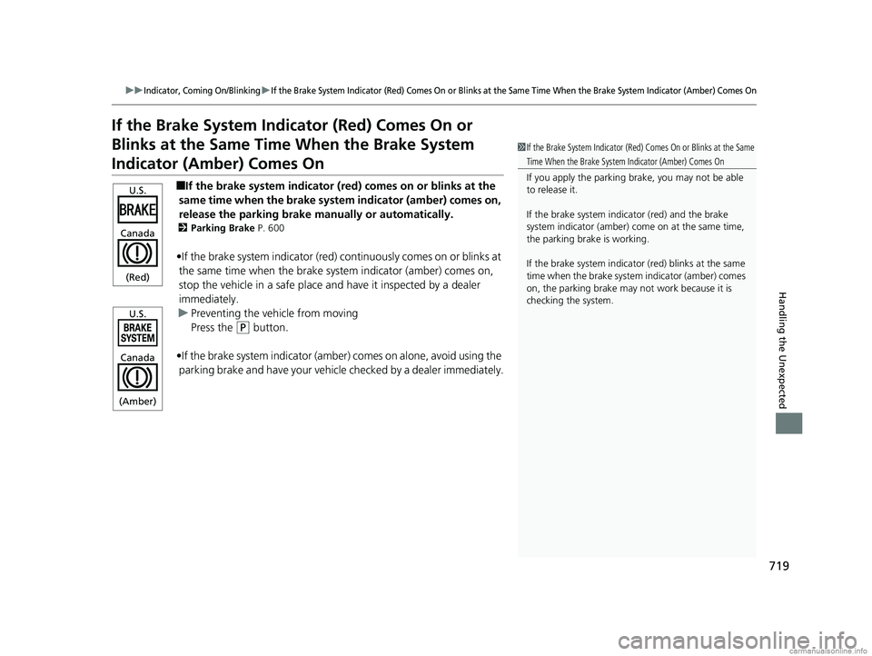
If the Brake System Indicator (Red) Comes On or
Blinks at the Same Time When the Brake System
Indicator (Amber) Comes On
■If the brake system indicator (red) comes on or blinks at the
same time when the brake syst em indicator (amber) comes on,
release the parking brake ma nually or automatically.
2Parking Brake P. 600
•If the brake system indicator (red) continuously comes on or blinks at
the same time when the brake sy stem indicator (amber) comes on,
stop the vehicle in a safe place an d have it inspected by a dealer
immediately.
u Preventing the ve hicle from moving
Press the
(P button.
•If the brake system indicator (amber ) comes on alone, avoid using the
parking brake and have your vehicle checked by a dealer immediately.
1If the Brake System Indicator (Red) Comes On or Blinks at the Same
Time When the Brake System Indicator (Amber) Comes On
If you apply the parking br ake, you may not be able
to release it.
If the brake system indicator (red) and the brake
system indicator (amber) come on at the same time,
the parking brake is working.
If the brake system indicator (red) blinks at the same
time when the brake system indicator (amber) comes
on, the parking brake may not work because it is
checking the system.
U.S.
Canada
(Red)
U.S.
Canada
(Amber)
18 US ODYSSEY-31THR6010.book 719 ページ 2018年12月6日 木曜日 午後4時18分
Page 722 of 763
720
uuIndicator, Coming On/Blinking uIf the Electric Power Steering (EPS) System Indicator Comes On
Handling the Unexpected
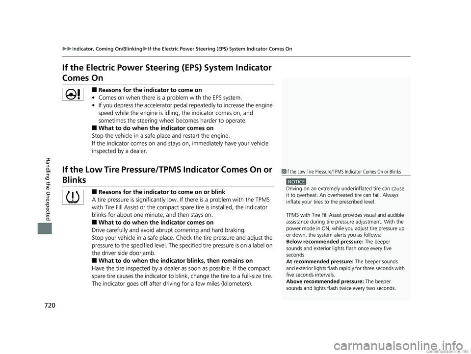
If the Electric Power Steeri ng (EPS) System Indicator
Comes On
■Reasons for the indicator to come on
• Comes on when there is a problem with the EPS system.
• If you depress the accelerator pedal repeatedly to increase the engine
speed while the engine is idling, the indicator comes on, and
sometimes the steering wheel becomes harder to operate.
■What to do when the indicator comes on
Stop the vehicle in a safe place and restart the engine.
If the indicator comes on and stays on, immediately have your vehicle
inspected by a dealer.
If the Low Tire Pressure/TPMS Indicator Comes On or
Blinks
■Reasons for the indicator to come on or blink
A tire pressure is significantly low. If there is a problem with the TPMS
with Tire Fill Assist or the compact spare tire is installed, the indicator
blinks for about one mi nute, and then stays on.
■What to do when the indicator comes on
Drive carefully and avoid abrupt cornering and hard braking.
Stop your vehicle in a safe place. Ch eck the tire pressure and adjust the
pressure to the specified level. The sp ecified tire pressure is on a label on
the driver side doorjamb.
■What to do when the indicator blinks, then remains on
Have the tire inspected by a dealer as soon as possible. If the compact
spare tire causes the indicator to blink, change the tire to a full-size tire.
The indicator goes off after driv ing for a few miles (kilometers).
1If the Low Tire Pressure/TPMS Indicator Comes On or Blinks
NOTICE
Driving on an extremely unde rinflated tire can cause
it to overheat. An overheated tire can fail. Always
inflate your tires to the prescribed level.
TPMS with Tire Fill Assist provides visual and audible
assistance during tire pre ssure adjustment. With the
power mode in ON, while y ou adjust tire pressure up
or down, the system alerts you as follows:
Below recommended pressure: The beeper
sounds and exterior lights flash once every five
seconds.
At recommended pressure: The beeper sounds
and exterior lights flash rapi dly for three seconds with
five seconds intervals.
Above recommended pressure: The beeper
sounds and lights flash tw ice every two seconds.
18 US ODYSSEY-31THR6010.book 720 ページ 2018年12月6日 木曜日 午後4時18分
Page 723 of 763
721
uuIndicator, Coming On/BlinkinguIf the Transmission System Indicator Blinks along with the Warning Message
Handling the Unexpected
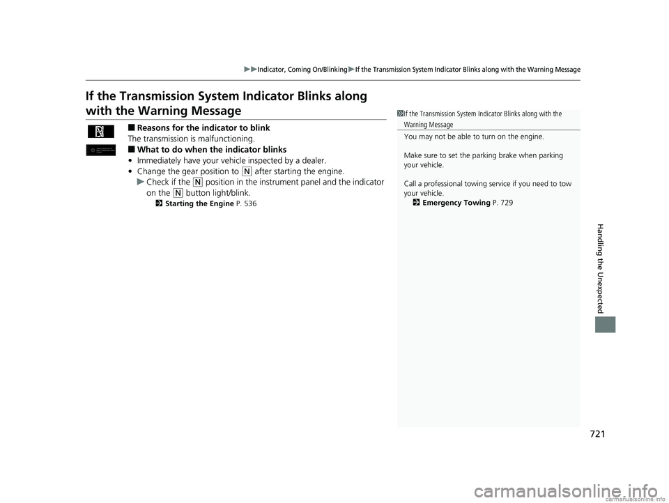
If the Transmission System Indicator Blinks along
with the Warning Message
■Reasons for the indicator to blink
The transmission is malfunctioning.
■What to do when the indicator blinks
• Immediately have your vehicle inspected by a dealer.
• Change the gear position to
(N after starting the engine.
u Check if the
(N position in the instrume nt panel and the indicator
on the
(N button light/blink.
2 Starting the Engine P. 536
1If the Transmission System In dicator Blinks along with the
Warning Message
You may not be able to turn on the engine.
Make sure to set the parking brake when parking
your vehicle.
Call a professional towing service if you need to tow
your vehicle. 2 Emergency Towing P. 729
18 US ODYSSEY-31THR6010.book 721 ページ 2018年12月6日 木曜日 午後4時18分
Page 724 of 763
722
Handling the Unexpected
Fuses
Fuse Locations
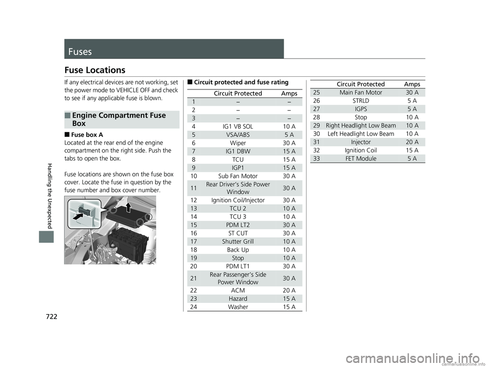
If any electrical devices are not working, set
the power mode to VEHICLE OFF and check
to see if any applic able fuse is blown.
■Fuse box A
Located at the rear end of the engine
compartment on the ri ght side. Push the
tabs to open the box.
Fuse locations are shown on the fuse box
cover. Locate the fuse in question by the
fuse number and box cover number.
■Engine Compartment Fuse
Box
■Circuit protected and fuse rating
Circuit ProtectedAmps
1−−
2− −
3−−
4 IG1 VB SOL 10 A
5VSA/ABS5 A
6 Wiper 30 A
7IG1 DBW15 A
8TCU 15A
9IGP115 A
10 Sub Fan Motor 30 A
11Rear Driver’s Side Power Window30 A
12 Ignition Coil/Injector 30 A
13TCU 210 A
14 TCU 3 10 A
15PDM LT230 A
16ST CUT 30 A
17Shutter Grill10 A
18 Back Up 10 A
19Stop10 A
20 PDM LT1 30 A
21Rear Passenger’s Side Power Window30 A
22 ACM 20 A
23Hazard15 A
24 Washer 15 A
25Main Fan Motor30 A
26 STRLD 5 A
27IGPS5 A
28 Stop 10 A
29Right Headlight Low Beam10 A
30 Left Headlight Low Beam 10 A
31Injector20 A
32 Ignition Coil 15 A
33FET Module5 A
Circuit ProtectedAmps
18 US ODYSSEY-31THR6010.book 722 ページ 2018年12月6日 木曜日 午後4時18分
Page 725 of 763
723
uuFuses uFuse Locations
Continued
Handling the Unexpected
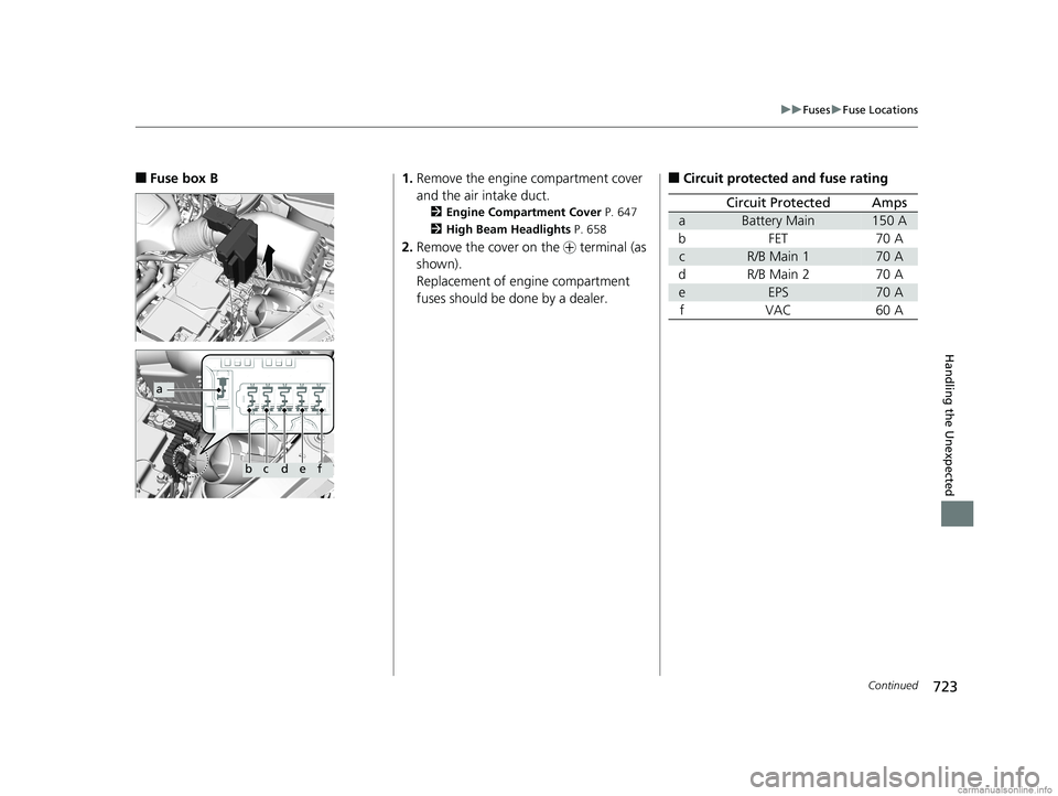
■Fuse box B
a
bcdef
1. Remove the engine compartment cover
and the air intake duct.
2 Engine Compartment Cover P. 647
2 High Beam Headlights P. 658
2.Remove the cover on the + terminal (as
shown).
Replacement of engine compartment
fuses should be done by a dealer.
■Circuit protected and fuse rating
Circuit ProtectedAmps
aBattery Main150 A
bFET70 A
cR/B Main 170 A
dR/B Main 270 A
eEPS70 A
fVAC60 A
18 US ODYSSEY-31THR6010.book 723 ページ 2018年12月6日 木曜日 午後4時18分
Page 726 of 763
724
uuFuses uFuse Locations
Handling the Unexpected
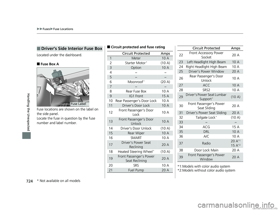
Located under the dashboard.
■Fuse Box A
Fuse locations are shown on the label on
the side panel.
Locate the fuse in question by the fuse
number and label number.
■Driver’s Side Interior Fuse Box
Fuse Label
■Circuit protected and fuse rating
Circuit ProtectedAmps
1Meter10 A
2Starter Motor*(10 A)
3Option10 A
4−−
5−−
6Moonroof*(20 A)
7−−
8Rear Fuse Box10 A
9IG1 Front15 A
10 Rear Passenger’s Door Lock 10 A
11Driver’s Door Lock10 A
12 Front Passenger’s Door
Lock 10 A
13Front Passenger’s Door
Unlock10 A
14 Driver’s Door Unlock (10 A)
15Rear Wiper10 A
16 SMART 10 A
17Driver’s Power Seat Reclining20 A
18 Heated Steering Wheel
*(10 A)
19Front Passenger’s Power Seat Reclining20 A
20 SRS 10 A
21Fuel Pump20 A*1:Models with color audio system
*2:Models without color audio system22
Front Accessory Power
Socket 20 A
23Left Headlight High Beam10 A
24 Right Headlight High Beam 10 A
25Driver’s Power Window20 A
26 Rear Passenger’s Door
Unlock 10 A
27ACC10 A
28 SRS2 10 A
29Driver’s Power Seat Lumbar Support*(10 A)
30 Front Passenger’s Power
Seat Sliding 20 A
31Driver’s Power Seat Sliding20 A
32 Tailgate Lock*(10 A)
33−−
34 ACG 15 A
35DRL10 A
36 A/C 10 A
37Radio20 A*1
15 A*2
38 Door Lock Main 20 A
39Front Passenger’s Power Window20 A
Circuit ProtectedAmps
* Not available on all models
18 US ODYSSEY-31THR6010.book 724 ページ 2018年12月6日 木曜日 午後4時18分
Page 727 of 763
725
uuFuses uFuse Locations
Continued
Handling the Unexpected
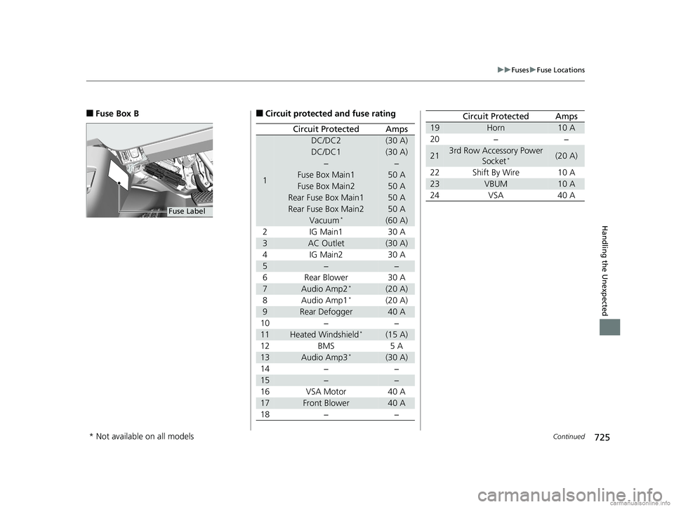
■Fuse Box B
Fuse Label
■Circuit protected and fuse rating
Circuit ProtectedAmps
1
DC/DC2(30 A)
DC/DC1(30 A)
−−
Fuse Box Main150 A
Fuse Box Main250 A
Rear Fuse Box Main150 A
Rear Fuse Box Main250 A
Vacuum*(60 A)
2 IG Main1 30 A
3AC Outlet(30 A)
4 IG Main2 30 A
5−−
6 Rear Blower 30 A
7Audio Amp2*(20 A)
8Audio Amp1*(20 A)
9Rear Defogger40 A
10 − −
11Heated Windshield*(15 A)
12 BMS 5 A
13Audio Amp3*(30 A)
14 − −
15−−
16 VSA Motor 40 A
17Front Blower40 A
18 − −
19Horn10 A
20 − −
213rd Row Accessory Power Socket*(20 A)
22 Shift By Wire 10 A
23VBUM10 A
24 VSA 40 A
Circuit ProtectedAmps
* Not available on all models
18 US ODYSSEY-31THR6010.book 725 ページ 2018年12月6日 木曜日 午後4時18分
Page 728 of 763
726
uuFuses uFuse Locations
Handling the Unexpected
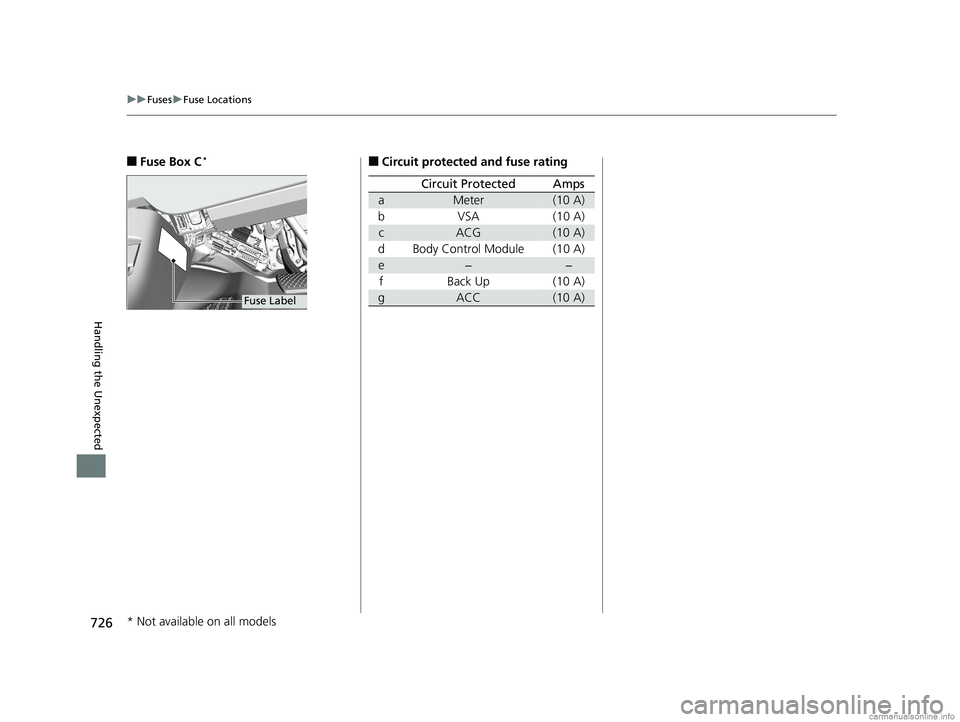
■Fuse Box C*
Fuse Label
■Circuit protected and fuse rating
Circuit ProtectedAmps
aMeter(10 A)
bVSA (10 A)
cACG(10 A)
d Body Control Module (10 A)
e−−
f Back Up (10 A)
gACC(10 A)
* Not available on all models
18 US ODYSSEY-31THR6010.book 726 ページ 2018年12月6日 木曜日 午後4時18分
Page 729 of 763
727
uuFuses uFuse Locations
Handling the Unexpected
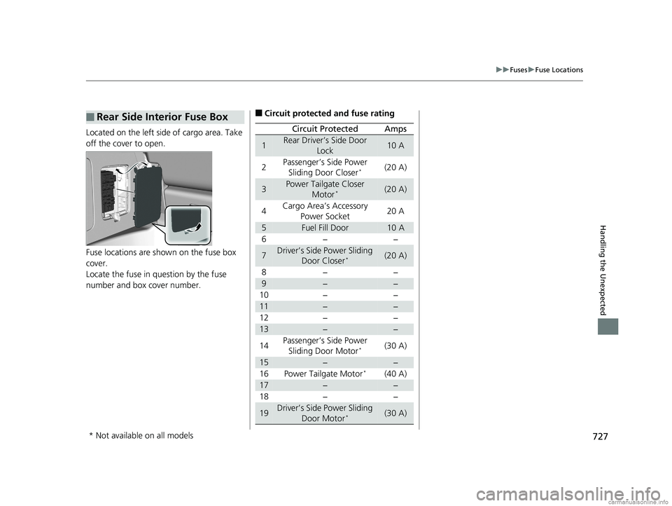
Located on the left side of cargo area. Take
off the cover to open.
Fuse locations are shown on the fuse box
cover.
Locate the fuse in question by the fuse
number and box cover number.
■Rear Side Interior Fuse Box■Circuit protected and fuse rating
Circuit ProtectedAmps
1Rear Driver’s Side Door
Lock10 A
2Passenger’s Side Power Sliding Door Closer*(20 A)
3Power Tailgate Closer Motor*(20 A)
4Cargo Area’s Accessory
Power Socket20 A
5Fuel Fill Door10 A
6−−
7Driver’s Side Power Sliding Door Closer*(20 A)
8−−
9−−
10 − −
11−−
12 − −
13−−
14 Passenger’s Side Power
Sliding Door Motor
*(30 A)
15−−
16 Power Tailgate Motor*(40 A)
17−−
18 − −
19Driver’s Side Power Sliding
Door Motor*(30 A)
* Not available on all models
18 US ODYSSEY-31THR6010.book 727 ページ 2018年12月6日 木曜日 午後4時18分
Page 730 of 763
728
uuFuses uInspecting and Changing Fuses
Handling the Unexpected
Inspecting and Changing Fuses
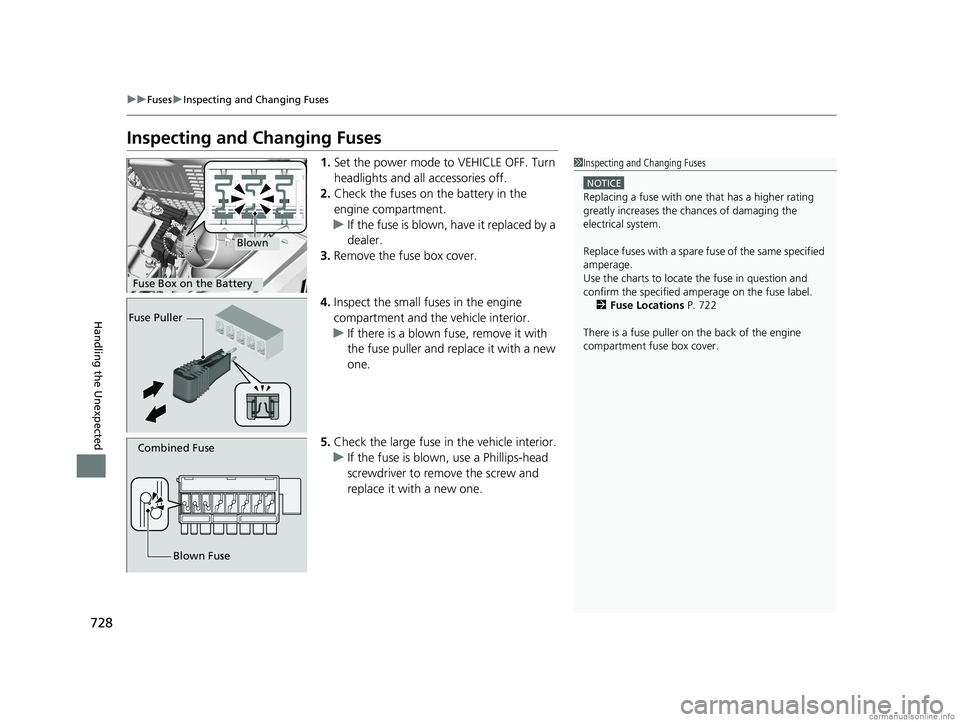
1. Set the power mode to VEHICLE OFF. Turn
headlights and all accessories off.
2. Check the fuses on the battery in the
engine compartment.
u If the fuse is blown, have it replaced by a
dealer.
3. Remove the fuse box cover.
4. Inspect the small fuses in the engine
compartment and the vehicle interior.
u If there is a blown fuse, remove it with
the fuse puller and replace it with a new
one.
5. Check the large fuse in the vehicle interior.
u If the fuse is blown, use a Phillips-head
screwdriver to remo ve the screw and
replace it with a new one.1 Inspecting and Changing Fuses
NOTICE
Replacing a fuse with on e that has a higher rating
greatly increases the chances of damaging the
electrical system.
Replace fuses with a spare fuse of the same specified
amperage.
Use the charts to locate the fuse in question and
confirm the specified amperage on the fuse label. 2 Fuse Locations P. 722
There is a fuse puller on the back of the engine
compartment fuse box cover.
Blown
Fuse Box on the Battery
Fuse Puller
Combined Fuse
Blown Fuse
18 US ODYSSEY-31THR6010.book 728 ページ 2018年12月6日 木曜日 午後4時18分