sensor HONDA PILOT 2004 1.G Owners Manual
[x] Cancel search | Manufacturer: HONDA, Model Year: 2004, Model line: PILOT, Model: HONDA PILOT 2004 1.GPages: 248, PDF Size: 2.98 MB
Page 23 of 248
Your airbag system includes:Two SRS (Supplemental Restraint
System) f ront airbags. The driver’s
airbag is stored in the center of
the steering wheel; the f ront
passenger’sairbagisstoredinthe
dashboard. Both are marked ‘‘SRS
AIRBAG.’’
Two side airbags, one f or the
driver and one f or a f ront
passenger. The airbags are stored
in the outer edges of the seat-
backs. Both are marked ‘‘SIDE
AIRBAG’’ (see page ).
Sensors that can detect a
moderate to severe frontal or side
collision. Automatic front seat belt
tensioners (see page ).
The dealer should also inspect the
anchors f or damage and replace
them if needed. If the automatic seat
belt tensioners activate during a
crash, they must be replaced.
For inf ormation on how to clean your
seat belts, see page .
For saf ety, you should check the
condition of your seat belts regularly.
Pull each belt out f ully and look f or
f rays, cuts, burns, and wear. Check
that the latches work smoothly and
the belts retract easily. Any belt that
is not in good condition or not
working properly will not provide
good protection and should be
replaced as soon as possible.
Honda provides a lif etime warranty
on seat belts f or U.S. models. See
your
booklet f or details.
If a seat belt is worn during a crash,
it must be replaced by the dealer. A
belt that has been worn during a
crash may not provide the same level
of protection in a subsequent crash. 22
18
184
Honda Warranty Inf ormation
A irbag System Components
Seat Belt Maintenance
Driver and Passenger Saf ety
Additional Inf ormation About Your Seat Belts, Additional Inf ormation About Your Airbags
19
Not checking or maintaining
seat belts can result in serious
injury or death if the seat belts
do not work properly when
needed.
Check your seat belts regularly
and have any problem
corrected as soon as possible.
Page 24 of 248
A sophisticated electronic system
that continually monitors and
records inf ormation about the
sensors, the control unit, the
airbag activators, and driver and
frontpassengerseatbeltusewhen
the ignition is in the ON (II)
position.
An indicator on the dashboard that
alerts you that the passenger’s
f ront airbag has been turned of f
(see page ).
Emergency backup power in case
your vehicle’s electrical system is
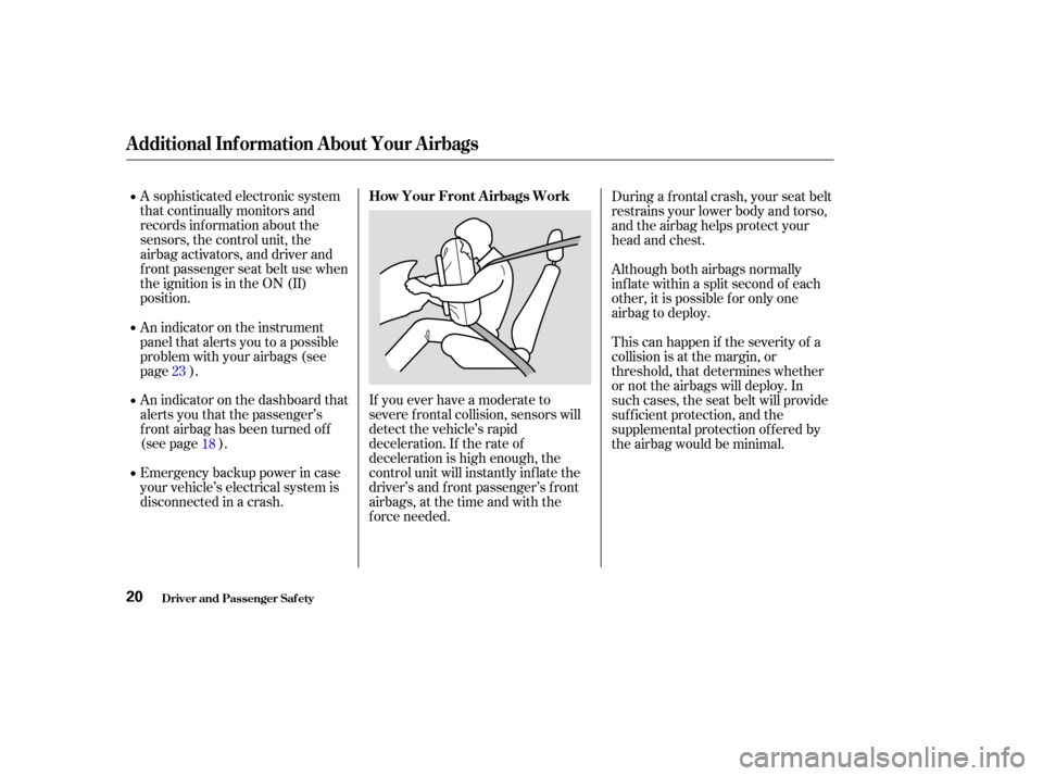
disconnected in a crash.If you ever have a moderate to
severe f rontal collision, sensors will
detect the vehicle’s rapid
deceleration. If the rate of
deceleration is high enough, the
control unit will instantly inf late the
driver’s and f ront passenger’s f ront
airbags, at the time and with the
f orce needed. During a frontal crash, your seat belt
restrains your lower body and torso,
and the airbag helps protect your
head and chest.
Although both airbags normally
inf late within a split second of each
other, it is possible f or only one
airbag to deploy.
This can happen if the severity of a
collision is at the margin, or
threshold, that determines whether
or not the airbags will deploy. In
such cases, the seat belt will provide
suf f icient protection, and the
supplemental protection of f ered by
the airbag would be minimal.
An indicator on the instrument
panel that alerts you to a possible
problem with your airbags (see
page ).
18
23
Additional Inf ormation About Your Airbags
How Your Front A irbags Work
Driver and Passenger Saf ety20
Page 26 of 248
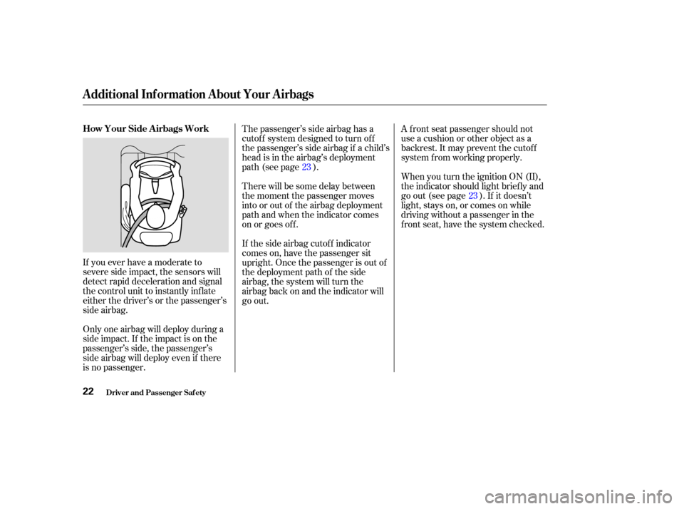
If you ever have a moderate to
severe side impact, the sensors will
detect rapid deceleration and signal
the control unit to instantly inf late
either the driver’s or the passenger’s
side airbag.
Only one airbag will deploy during a
side impact. If the impact is on the
passenger’s side, the passenger’s
side airbag will deploy even if there
is no passenger.A f ront seat passenger should not
use a cushion or other object as a
backrest. It may prevent the cutof f
system f rom working properly.
When you turn the ignition ON (II),
the indicator should light brief ly and
goout(seepage ).Ifitdoesn’t
light, stays on, or comes on while
driving without a passenger in the
f ront seat, have the system checked.
The passenger’s side airbag has a
cutof f system designed to turn of f
the passenger’s side airbag if a child’s
head is in the airbag’s deployment
path (see page ).
There will be some delay between
the moment the passenger moves
into or out of the airbag deployment
pathandwhentheindicatorcomes
on or goes of f .
If the side airbag cutof f indicator
comes on, have the passenger sit
upright. Once the passenger is out of
the deployment path of the side
airbag, the system will turn the
airbag back on and the indicator will
go out. 23
23
Additional Inf ormation About Your Airbags
Driver and Passenger Saf ety
How Your Side A irbags Work
22
Page 59 of 248

This shows the temperature of the
engine’s coolant. During normal
operation, the pointer should rise
from the bottom white mark to about
the middle white mark. In severe
driving conditions, such as very hot
weather or a long period of uphill
driving, the pointer may rise to the
upper white mark. If it reaches the
red (Hot) mark, pull saf ely to the
side of the road. Turn to page f or
instructions and precautions on
checking the engine’s cooling
system.The temperature sensor is in the
f ront bumper. Theref ore, the temper-
ature reading can be af f ected by heat
ref lection f rom the road surf ace, en-
gine heat, and the exhaust f rom
surrounding traf f ic. This can cause
an incorrect temperature reading
when your speed is under
19 mph (30 km/h). This indicator displays the outside
temperature in Fahrenheit (U.S.
models) or Centigrade (Canadian
models). To see the outside
temperature, press and release the
Select/Reset button until the
temperature is displayed.
The sensor delays the display update
until it reaches the correct out side
temperature, this may take several
minutes.In certain weather conditions,
temperature readings near f reezing
(32°F, 0°C) could mean that ice is
f orming on the road surf ace.
204On EX model
Temperature Gauge Outside Temperature Indicator
Gauges
Inst rument s and Cont rols55
Page 91 of 248
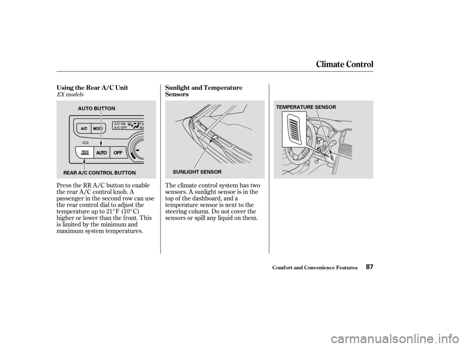
Theclimatecontrolsystemhastwo
sensors. A sunlight sensor is in the
top of the dashboard, and a
temperature sensor is next to the
steering column. Do not cover the
sensors or spill any liquid on them.
Press the RR A/C button to enable
the rear A/C control knob. A
passenger in the second row can use
the rear control dial to adjust the
temperature up to 21°F (10°C)
higher or lower than the f ront. This
is limited by the minimum and
maximum system temperatures.
EX models
Climat e Cont rol
Comf ort and Convenience Feat ures
Using the Rear A /C Unit
Sunlight and T emperature
Sensors
87
REAR A/C CONTROL BUTTON SUNLIGHT SENSORTEMPERATURE SENSOR
AUTO BUTTON
Page 228 of 248

The exhaust emissions controls
include f our systems: PGM-FI,
Ignition Timing Control, Exhaust
Gas Recirculation and Three Way
Catalytic Converter. These four
systems work together to control the
engine’s combustion and minimize
the amount of HC, CO, and NOx that
comes out the tailpipe. The exhaust
emissions control systems are
separate f rom the crankcase and
evaporative emissions control
systems.
The PGM-FI System uses sequential
multiport f uel injection.
It has three subsystems: Air Intake,
Engine Control, and Fuel Control.
The Powertrain Control Module
(PCM) uses various sensors to
determine how much air is going
into the engine. It then controls how
much f uel to inject under all
operating conditions.The emissions control systems are
designed and certif ied to work to-
gether in reducing emissions to
levels that comply with the Clean Air
Act. To make sure the emissions
remain low, you should use only new
Honda replacement parts or their
equivalent f or repairs. Using lower
qualitypartsmayincreasethe
emissions f rom your vehicle.
The emissions control systems are
covered by warranties separate from
the rest of your vehicle. Read your
warranty manual f or more informa-
tion.
The three way catalytic converter is
in the exhaust system. Through
chemical reactions, it converts HC,
CO, and NOx in the engine’s exhaust
to carbon dioxide (CO ), dinitrogen
(N ), and water vapor. This system constantly adjusts the
ignition timing, reducing the amount
of HC, CO, and NOx produced.
The Exhaust Gas Recirculation
(EGR) system takes some of the
exhaust gas and routes it back into
the intake manif old. Adding exhaust
gas to the air/f uel mixture reduces
the amount of NOx produced when
the f uel is burned.
2
2
Exhaust Emissions Controls Replacement Parts
PGM-FI Syst emT hree Way Cat alyt ic Convert er
Ignit ion T iming Cont rol Syst em
Exhaust Gas Recirculat ion (EGR)Syst em
Emissions Cont rols
T echnical Inf ormation224
Page 246 of 248
....
START (Ignition Key Position) . 64
.......................
Starting the Engine .137
In Cold Weather at High ..................................
Altitude .137
................
With a Dead Battery . 202
..............
State Emissions Testing . 226
........
Steam Coming f rom Engine . 204
Steering Wheel ..................................
Adjustment .61
.............
Anti-theft Column Lock . 64
...............................
Buttons .101, 116
.....................
Stereo Sound System .88
....................
Storing Your Vehicle .194
..........................
Sunglasses Holder .78
..........................................
Sun Visor .79
Supplemental Restraint System ......................................
Servicing .24
.........................
SRS Indicator .23 ,48
...................
System Components . 19
..................................
Synthetic Oil .172
......
Taillights, Changing Bulbs in . 182
.
Taking Care of the Unexpected . 195
......................................
Tape Player .98 Technical Descriptions
......
DOT Tire Quality Grading . 220
.....
Emissions Control Systems . 223
..........
State Emissions Testing . 226
Three Way Catalytic ...............................
Converter .225
.......................
Temperature Gauge .55
..........
Temperature, Inside Sensor . 87
....................
Temperature, Outside . 55
...................
Tensioners, Seat Belts . 18
........
Testing of Readiness Codes . 226
..............
Tether Anchorage Points . 37
............................
Thef t Protection .102
..
Three Way Catalytic Converter . 225
..........................
Time, Setting the .103
..................
Tilt the Steering Wheel . 61
....................................
Timing Belt .177
....................................
Tire Chains .192
.........
Tire, How to Change a Flat . 197
...............................................
Tires .188
..............................
Air Pressure .188
...................................
Balancing .190
.........................
Checking Wear .189
..........................
Compact Spare .196
......
DOT Tire Quality Grading . 220
......................................
Inf lation .188 ..................................
Inspection .189
..............................
Maintenance .190
...................................
Replacing .191
......................................
Rotating .190
...........................................
Snow .191
............................
Specif ications .219
................................
Tire Chains .192
..........................
Winter Driving .191
...................
Tools, Tire Changing . 197
Towing .....................................
A Trailer .147
................
Emergency Wrecker . 208
....
Equipment and Accessories . 151
.......................
Traction Devices .192
Your Vehicle Behind a ............................
Motorhome .154
.............................
Weight Limit .150
.............................
Trailer Loading .147
......................
Trailer Towing Tips .152
Transmission ...............
Checking Fluid Level . 176
...........................
Fluid Selection .176
..............
Identif ication Number . 216
.............
Shif ting the Automatic . 138
.....................................
Treadwear .220
.......................................
Trip Meter .54
Index
T
VIII