charging HUMMER H3 2010 Owners Manual
[x] Cancel search | Manufacturer: HUMMER, Model Year: 2010, Model line: H3, Model: HUMMER H3 2010Pages: 410, PDF Size: 2.24 MB
Page 4 of 410
iv Introduction
{WARNING
These mean there is something
that could hurt you or other
people.
Notice: This means there is
something that could result in
property or vehicle damage.
This would not be covered by
the vehicle's warranty.
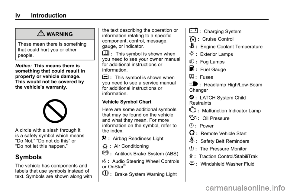
A circle with a slash through it
is a safety symbol which means
“Do Not,” “Do not do this” or
“Do not let this happen.”
Symbols
The vehicle has components and
labels that use symbols instead of
text. Symbols are shown along with the text describing the operation or
information relating to a specific
component, control, message,
gauge, or indicator.
M:
This symbol is shown when
you need to see your owner manual
for additional instructions or
information.
*: This symbol is shown when
you need to see a service manual
for additional instructions or
information.
Vehicle Symbol Chart
Here are some additional symbols
that may be found on the vehicle
and what they mean. For more
information on the symbol, refer to
the index.
9: Airbag Readiness Light
#:Air Conditioning
!:Antilock Brake System (ABS)
g:Audio Steering Wheel Controls
or OnStar®
$: Brake System Warning Light
":Charging System
I:Cruise Control
B: Engine Coolant Temperature
O:Exterior Lamps
#:Fog Lamps
.: Fuel Gauge
+:Fuses
i: Headlamp High/Low-Beam
Changer
j: LATCH System Child
Restraints
*: Malfunction Indicator Lamp
::Oil Pressure
}:Power
/:Remote Vehicle Start
>:Safety Belt Reminders
7:Tire Pressure Monitor
F:Traction Control/StabiliTrak
M:Windshield Washer Fluid
Page 115 of 410
Instruments and Controls 5-1
Instruments and
Controls
Controls
Steering Wheel Adjustment . . . 5-2
Horn . . . . . . . . . . . . . . . . . . . . . . . . . . 5-2
Windshield Wiper/Washer . . . . . 5-2
Rear Window Wiper/Washer . . . . . . . . . . . . . . . . . . . . . . 5-3
Compass . . . . . . . . . . . . . . . . . . . . . 5-3
Clock . . . . . . . . . . . . . . . . . . . . . . . . . 5-4
Power Outlets . . . . . . . . . . . . . . . . . 5-5
Cigarette Lighter . . . . . . . . . . . . . . 5-5
Ashtrays . . . . . . . . . . . . . . . . . . . . . . 5-6
Warning Lights, Gauges, and
Indicators
Warning Lights, Gauges, and Indicators . . . . . . . . . . . . . . . . . . . . 5-6
Instrument Cluster . . . . . . . . . . . . 5-7
Speedometer . . . . . . . . . . . . . . . . . 5-8
Odometer . . . . . . . . . . . . . . . . . . . . . 5-8
Trip Odometer . . . . . . . . . . . . . . . . . 5-8 Tachometer . . . . . . . . . . . . . . . . . . . 5-8
Fuel Gauge . . . . . . . . . . . . . . . . . . . 5-8
Engine Coolant Temperature
Gauge . . . . . . . . . . . . . . . . . . . . . . . 5-9
Safety Belt Reminders . . . . . . . . 5-9
Airbag Readiness Light . . . . . . 5-10
Passenger Airbag Status
Indicator . . . . . . . . . . . . . . . . . . . . 5-11
Charging System Light . . . . . . . 5-11
Malfunction Indicator Lamp . . . . . . . . . . . . . 5-12
Brake System Warning Light . . . . . . . . . . . . . . . . . . . . . . . 5-14
Antilock Brake System (ABS) Warning Light . . . . . . . . . . . . . . 5-15
Up-Shift Light . . . . . . . . . . . . . . . . 5-15
Traction Control System (TCS)/StabiliTrak
®Light . . . . 5-16
Tire Pressure Light . . . . . . . . . . 5-16
Engine Oil Pressure Light . . . . 5-17
Security Light . . . . . . . . . . . . . . . . 5-17
High-Beam on Light . . . . . . . . . 5-17
Cruise Control Light . . . . . . . . . 5-18
Information Displays
Driver Information Center (DIC) . . . . . . . . . . . . . . . 5-18
Vehicle Messages
Vehicle Messages . . . . . . . . . . . 5-21
Battery Voltage and ChargingMessages . . . . . . . . . . . . . . . . . . 5-21
Brake System Messages . . . . 5-22
Door Ajar Messages . . . . . . . . . 5-22
Engine Cooling System Messages . . . . . . . . . . . . . . . . . . 5-23
Engine Oil Messages . . . . . . . . 5-23
Engine Power Messages . . . . 5-23
Fuel System Messages . . . . . . 5-24
Lamp Messages . . . . . . . . . . . . . 5-24
Ride Control System Messages . . . . . . . . . . . . . . . . . . 5-24
Service Vehicle Messages . . . 5-25
Tire Messages . . . . . . . . . . . . . . . 5-25
Transmission Messages . . . . . 5-25
Universal Remote System
Universal Remote System . . . 5-26
Universal Remote System Programming . . . . . . . . . . . . . . . 5-26
Universal Remote System Operation . . . . . . . . . . . . . . . . . . 5-30
Page 125 of 410

Instruments and Controls 5-11
Passenger Airbag Status
Indicator
The vehicle has the passenger
sensing system. SeePassenger
Sensing System
on page 3‑35for
important safety information. The
instrument panel has a passenger
airbag status indicator.
United States
Canada
When the vehicle is started, the
passenger airbag status indicator
will light ON and OFF, or the symbol
for on and off, for several seconds as a system check. Then, after
several more seconds, the status
indicator will light either ON or OFF,
or either the on or off symbol to let
you know the status of the right front
passenger frontal airbag.
If the word ON or the on symbol is
lit on the passenger airbag status
indicator, it means that the right
front passenger frontal airbag is
enabled (may inflate).
If the word OFF or the off symbol is
lit on the airbag status indicator, it
means that the passenger sensing
system has turned off the right front
passenger frontal airbag.
If, after several seconds, both status
indicator lights remain on, or if there
are no lights at all, there may be
a problem with the lights or the
passenger sensing system. See
your dealer for service.
{WARNING
If the airbag readiness light
ever comes on and stays on, it
means that something may be
wrong with the airbag system.
To help avoid injury to yourself or
others, have the vehicle serviced
right away. See
Airbag Readiness
Light
on page 5‑10for more
information, including important
safety information.
Charging System Light
This light comes on briefly when the
ignition key is turned, but the engine
is not running, as a check to show it
is working.
Page 126 of 410

5-12 Instruments and Controls
It should go out once the engine
starts. If it stays on, or comes on
while driving, there could be a
problem with the charging system.
A charging system message in the
Driver Information Center (DIC)
may also appear. SeeBattery
Voltage and Charging Messages
on
page 5‑21for more information.
This light could indicate that there
are problems with a generator drive
belt, or that there is an electrical
problem. Have it checked right
away. If the vehicle must be driven a
short distance with the light on, turn
off all the accessories, such as the
radio and air conditioner.
Malfunction
Indicator Lamp
A computer system called OBD II
(On-Board Diagnostics-Second
Generation) monitors operation of
the fuel, ignition, and emission
control systems. It ensures that emissions are at acceptable levels
for the life of the vehicle, helping to
produce a cleaner environment.
This light comes on when the
ignition is on, but the engine is not
running, as a check to show it is
working. If it does not, have the
vehicle serviced by your dealer.
If the check engine light comes on
and stays on, while the engine is
running, this indicates that there is
an OBD II problem and service is
required.
Malfunctions often are indicated by
the system before any problem is
apparent. Being aware of the light
can prevent more serious damage
to the vehicle. This system assists
the service technician in correctly
diagnosing any malfunction.Notice:
If the vehicle is
continually driven with this light
on, after a while, the emission
controls might not work as well,
the vehicle's fuel economy might
not be as good, and the engine
might not run as smoothly. This
could lead to costly repairs that
might not be covered by the
vehicle warranty.
Notice: Modifications made to the
engine, transmission, exhaust,
intake, or fuel system of the
vehicle or the replacement of
the original tires with other
than those of the same Tire
Performance Criteria (TPC) can
affect the vehicle's emission
controls and can cause this light
to come on. Modifications to
these systems could lead to
costly repairs not covered by
the vehicle warranty. This
could also result in a failure
to pass a required Emission
Inspection/Maintenance test.
See Accessories and
Modifications on page 10‑3.
Page 135 of 410
Instruments and Controls 5-21
The following are the available
modes:
RFA 1 (default):This mode flashes
the parking lamps when you press
the lock or unlock buttons on the
RKE transmitter.
RFA 2: This mode flashes the
parking lamps and sounds the horn
when you press the lock button on
the RKE transmitter. This mode also
flashes the parking lamps when you
press the unlock button on the RKE
transmitter.
RFA 3: This mode flashes the
parking lamps and sounds the horn
when you press the lock or unlock
buttons on the RKE transmitter.
RFA 4: This mode disables RKE
feedback. There will be no feedback
when you press the lock or unlock
buttons on the RKE transmitter.Vehicle Messages
Messages are displayed on the
DIC to notify the driver that the
status of the vehicle has changed
and that some action may be
needed by the driver to correct
the condition. Multiple messages
may appear one after another.
The messages are displayed for
several seconds each.
Some messages may not require
immediate action, but you should
press and release the trip odometer
reset stem to acknowledge that
you received the messages and to
clear them from the display. Each
message must be acknowledged
individually.
Some messages cannot be cleared
from the DIC display because they
are more urgent. These messages
require action before they can be
cleared. You should take any
messages that appear on the display seriously and remember that
clearing the messages only makes
the messages disappear, not correct
the problem.
The following are the possible
messages that can be displayed
and some information about them.
Battery Voltage and
Charging Messages
SERVICE CHARG (Charge)
SYS (System)
This message displays if there is a
problem with the battery charging
system. Under certain conditions,
the battery warning light may also
turn on in the instrument panel
cluster. See
Charging System Light
on page 5‑11. The battery will not
be charging at an optimal rate and
the vehicle will lose the ability to
enter the fuel economy mode.
Page 152 of 410
6-8 Lighting
Dome Lamp Override
The dome lamp override button is
located below the exterior lamps
control.
E(Dome Lamp Override): Press
the button in to turn the lamps off.
In this position, the dome lamps will
remain off when the doors are open.
To return the lamps to automatic
operation, press
Eagain and
return it to the out position. With the
button in this position, the dome
lamps will come on when a door is
opened.
Reading Lamps
The reading lamps are located in
the overhead console.
Press the button located next to
each lamp to turn them on or off.
These lamps will not come on with
the dome lamps.
Lighting Features
Exit Lighting
The interior lamps come on when
the key is removed from the ignition.
The lamps will not come on if the
dome override button is pressed in.
Battery Load
Management
The vehicle has Electric Power
Management (EPM) that estimates
the battery's temperature and state
of charge. It then adjusts the voltage
for best performance and extended
life of the battery. When the battery's state of charge
is low, the voltage is raised slightly
to quickly bring the charge back up.
When the state of charge is high,
the voltage is lowered slightly to
prevent overcharging. If the vehicle
has a voltmeter gauge or a voltage
display on the Driver Information
Center (DIC), you may see the
voltage move up or down. This is
normal. If there is a problem, an
alert will be displayed.
The battery can be discharged at
idle if the electrical loads are very
high. This is true for all vehicles.
This is because the generator
(alternator) may not be spinning fast
enough at idle to produce all the
power that is needed for very high
electrical loads.
Page 163 of 410
Infotainment System 7-9
Unknown:If this message is
received when tuned to channel 0,
there may be a receiver fault.
Consult with your dealer.
Chk XMRcvr: If this message does
not clear within a short period of
time, the receiver may have a fault.
Consult with your dealer.
Radio Reception
Frequency interference and static
can occur during normal radio
reception if items such as cell phone
chargers, vehicle convenience
accessories, and external electronic
devices are plugged into the
accessory power outlet. If there is
interference or static, unplug the
item from the accessory power
outlet.
AM
The range for most AM stations is
greater than for FM, especially at
night. The longer range can cause
station frequencies to interfere with
each other. For better radio
reception, most AM radio stations
boost the power levels during the
day, and then reduce these levels
during the night. Static can also
occur when things like storms and
power lines interfere with radio
reception. When this happens, try
reducing the treble on the radio.
FM Stereo
FM signals only reach about
16 to 65 km (10 to 40 mile). Although
the radio has a built-in electronic
circuit that automatically works to
reduce interference, some static
can occur, especially around tall
buildings or hills, causing the sound
to fade in and out.
XM™ Satellite Radio Service
XM Satellite Radio Service gives
digital radio reception from
coast-to-coast in the 48 contiguous
United States, and in Canada. Just
as with FM, tall buildings or hills can
interfere with satellite radio signals,
causing the sound to fade in and
out. In addition, traveling or standing
under heavy foliage, bridges,
garages, or tunnels may cause loss
of the XM signal for a period of time.
Cellular Phone Usage
Cellular phone usage may cause
interference with the vehicle's radio.
This interference may occur when
making or receiving phone calls,
charging the phone's battery,
or simply having the phone on.
This interference causes an
increased level of static while
listening to the radio. If static is
received while listening to the radio,
unplug the cellular phone and turn
it off.
Page 223 of 410
Driving and Operating 9-39
The shift lock release is always
functional except in the case of a
an uncharged or low voltage (less
than 9 volt) battery.
If the vehicle has an uncharged
battery or a battery with low voltage,
try charging or jump starting the
battery. SeeJump Starting
on
page 10‑86for more information.
To shift out of P (Park):
1. Apply the brake pedal.
2. Then press the shift lever button.
3. Move the shift lever to the desired position. If you still are unable to shift out
of P (Park):
1. Fully release the shift lever
button.
2. While holding down the brake pedal, press the shift lever
button again.
3. Move the shift lever to the desired position.
If you still cannot move the shift
lever from P (Park), consult your
dealer or a professional towing
service.
Parking
If the vehicle has a manual
transmission, before you get out of
the vehicle, move the shift lever into
R (Reverse), and firmly apply the
parking brake. Once the shift lever
has been placed into R (Reverse)
with the clutch pedal pressed in,
turn the ignition key to LOCK/OFF,
remove the key and release the
clutch.
If you are parking on a hill, or if
the vehicle is pulling a trailer, see
Driving Characteristics and Towing
Tips on page 9‑70.
Page 264 of 410
9-80 Driving and Operating
The trailer towing harness contains
the following seven trailer circuits:
.Yellow: Left Stop/Turn Signal
.Dark Green: Right Stop/Turn
Signal
.Brown: Taillamps
.White: Ground
.Light Green: Back-up Lamps
.Red: Battery Feed
.Dark Blue: Trailer Brake
If charging a remote (non‐vehicle)
battery, turn on the headlamps to
boost the vehicle system voltage to
properly charge the battery. Four-Wire Harness Adapter
If towing a light-duty trailer with
a standard four-way, flat pin
connector, an adapter is available
from your dealer.
Hold the adapter with the tab
pointing up.
Connect the adapter to the
seven‐pin universal heavy‐duty
trailer connector attached to the
bracket on the hitch platform. The
flip cap on the vehicle's harness
locks onto the tab and helps hold
the adapter in place. Plug the
four-way pin connector onto the
adapter.
Page 400 of 410

i-2 INDEX
B
Battery . . . . . . . . . . . . . . . . . . . . . . . 10-28Jump Starting . . . . . . . . . . . . . . . 10-86
Load Management . . . . . . . . . . . . . 6-8
Power Protection . . . . . . . . . . . . . . 6-9
Voltage and ChargingMessages . . . . . . . . . . . . . . . . . . . 5-21
Blade Replacement, Wiper . . . 10-32
Bluetooth . . . . . . . . . . . . . . . . . . . . . . 7-15
Brakes . . . . . . . . . . . . . . . . . . . . . . . . 10-26 Antilock . . . . . . . . . . . . . . . . . . . . . . . 9-50
Assist . . . . . . . . . . . . . . . . . . . . . . . . . 9-51
Fluid . . . . . . . . . . . . . . . . . . . . . . . . 10-27
Parking . . . . . . . . . . . . . . . . . . . . . . . 9-51
System Messages . . . . . . . . . . . . 5-22
Braking . . . . . . . . . . . . . . . . . . . . . . . . . 9-3
Break-In, New Vehicle . . . . . . . . . 9-33
Bulb Replacement . . . . . . . . . . . . 10-37
Fog Lamps . . . . . . . . . . . . . . . . . . . . 6-6
Halogen Bulbs . . . . . . . . . . . . . . 10-35
Headlamp Aiming . . . . . . . . . . . 10-33 Bulb Replacement (cont.)
Headlamps . . . . . . . . . . . . . . . . . 10-35
License Plate Lamps . . . . . . . 10-37
Taillamps, Turn
Signal,
Stoplamps, and
Back-Up Lamps . . . . 10-35, 10-36
Buying New Tires . . . . . . . . . . . . . 10-59
C
Calibration . . . . . . . . . . . . . . . . . . . . . . 5-3
California Fuel Requirements . . . . . . . . . . . 9-65
Perchlorate MaterialsRequirements . . . . . . . . . . . . . . . 10-3
Warning . . . . . . . . . . . . . . . . . . . . . . 10-2
Camera, Rear Vision . . . . . . . . . . 9-60
Canadian Vehicle Owners . . . . . . . . iii
Capacities and Specifications . . . . . . . . . . . . . . . . 12-2
Carbon Monoxide Engine Exhaust . . . . . . . . . . . . . . . 9-40
Tailgate . . . . . . . . . . . . . . . . . . . . . . . . 2-7
Winter Driving . . . . . . . . . . . . . . . . 9-24 Cargo
Cover . . . . . . . . . . . . . . . . . . . . . . . . . . 4-2
Management System . . . . . . . . . . 4-2
Tie Downs . . . . . . . . . . . . . . . . . . . . . 4-2
Cautions, Danger, and Warnings . . . . . . . . . . . . . . . . . . . . . . . . iii
CD Player . . . . . . . . . . . . . . . . . . . . . 7-10
Center Console Storage . . . . . . . . 4-1
Chains, Tire . . . . . . . . . . . . . . . . . . 10-64
Charging System Light . . . . . . . . 5-11
Check
Engine Lamp . . . . . . . . . . . . . . . . . 5-12
IgnitionTransmission Lock . . . . . . . . 10-31
Child Restraints Infants and Young
Children . . . . . . . . . . . . . . . . . . . . . 3-44
Lower Anchors and Tethers for Children . . . . . . . . . 3-51
Older Children . . . . . . . . . . . . . . . . 3-42
Securing . . . . . . . . . . 3-59, 3-61, 3-62
Systems . . . . . . . . . . . . . . . . . . . . . . 3-47
Where to Put the Restraint . . . 3-49